EP1385235B1 - Connecteur électrique - Google Patents
Connecteur électrique Download PDFInfo
- Publication number
- EP1385235B1 EP1385235B1 EP03015649A EP03015649A EP1385235B1 EP 1385235 B1 EP1385235 B1 EP 1385235B1 EP 03015649 A EP03015649 A EP 03015649A EP 03015649 A EP03015649 A EP 03015649A EP 1385235 B1 EP1385235 B1 EP 1385235B1
- Authority
- EP
- European Patent Office
- Prior art keywords
- terminal
- locking
- disengagement
- locking arm
- flexible
- Prior art date
- Legal status (The legal status is an assumption and is not a legal conclusion. Google has not performed a legal analysis and makes no representation as to the accuracy of the status listed.)
- Expired - Lifetime
Links
- 230000013011 mating Effects 0.000 description 8
- 238000003780 insertion Methods 0.000 description 5
- 230000037431 insertion Effects 0.000 description 5
- 230000002708 enhancing effect Effects 0.000 description 3
- 238000004519 manufacturing process Methods 0.000 description 3
- 230000002093 peripheral effect Effects 0.000 description 3
- 239000000470 constituent Substances 0.000 description 2
- 238000005192 partition Methods 0.000 description 2
- 238000005452 bending Methods 0.000 description 1
- 230000003467 diminishing effect Effects 0.000 description 1
- 238000012423 maintenance Methods 0.000 description 1
- 238000012986 modification Methods 0.000 description 1
- 230000004048 modification Effects 0.000 description 1
- 229920003002 synthetic resin Polymers 0.000 description 1
- 239000000057 synthetic resin Substances 0.000 description 1
Images



Classifications
-
- H—ELECTRICITY
- H01—ELECTRIC ELEMENTS
- H01R—ELECTRICALLY-CONDUCTIVE CONNECTIONS; STRUCTURAL ASSOCIATIONS OF A PLURALITY OF MUTUALLY-INSULATED ELECTRICAL CONNECTING ELEMENTS; COUPLING DEVICES; CURRENT COLLECTORS
- H01R13/00—Details of coupling devices of the kinds covered by groups H01R12/70 or H01R24/00 - H01R33/00
- H01R13/40—Securing contact members in or to a base or case; Insulating of contact members
- H01R13/42—Securing in a demountable manner
-
- H—ELECTRICITY
- H01—ELECTRIC ELEMENTS
- H01R—ELECTRICALLY-CONDUCTIVE CONNECTIONS; STRUCTURAL ASSOCIATIONS OF A PLURALITY OF MUTUALLY-INSULATED ELECTRICAL CONNECTING ELEMENTS; COUPLING DEVICES; CURRENT COLLECTORS
- H01R13/00—Details of coupling devices of the kinds covered by groups H01R12/70 or H01R24/00 - H01R33/00
- H01R13/40—Securing contact members in or to a base or case; Insulating of contact members
- H01R13/42—Securing in a demountable manner
- H01R13/422—Securing in resilient one-piece base or case, e.g. by friction; One-piece base or case formed with resilient locking means
-
- H—ELECTRICITY
- H01—ELECTRIC ELEMENTS
- H01R—ELECTRICALLY-CONDUCTIVE CONNECTIONS; STRUCTURAL ASSOCIATIONS OF A PLURALITY OF MUTUALLY-INSULATED ELECTRICAL CONNECTING ELEMENTS; COUPLING DEVICES; CURRENT COLLECTORS
- H01R13/00—Details of coupling devices of the kinds covered by groups H01R12/70 or H01R24/00 - H01R33/00
- H01R13/40—Securing contact members in or to a base or case; Insulating of contact members
- H01R13/42—Securing in a demountable manner
- H01R13/422—Securing in resilient one-piece base or case, e.g. by friction; One-piece base or case formed with resilient locking means
- H01R13/4223—Securing in resilient one-piece base or case, e.g. by friction; One-piece base or case formed with resilient locking means comprising integral flexible contact retaining fingers
-
- H—ELECTRICITY
- H01—ELECTRIC ELEMENTS
- H01R—ELECTRICALLY-CONDUCTIVE CONNECTIONS; STRUCTURAL ASSOCIATIONS OF A PLURALITY OF MUTUALLY-INSULATED ELECTRICAL CONNECTING ELEMENTS; COUPLING DEVICES; CURRENT COLLECTORS
- H01R43/00—Apparatus or processes specially adapted for manufacturing, assembling, maintaining, or repairing of line connectors or current collectors or for joining electric conductors
- H01R43/20—Apparatus or processes specially adapted for manufacturing, assembling, maintaining, or repairing of line connectors or current collectors or for joining electric conductors for assembling or disassembling contact members with insulating base, case or sleeve
- H01R43/22—Hand tools
Definitions
- the present invention relates to a connector, and more particularly, to a connector for a vehicle.
- This connector has a locking structure for a terminal, wherein a flexible locking arm (a so-called lance) locks a terminal received in a terminal receiving chamber of a connector housing.
- a connector having this type of locking structure for a terminal is disclosed in Japanese Patent Laid-Open Publication S61-218081 (published in 1986 ).
- This connector includes a terminal receiving chamber formed from the center of a connector housing toward the rear thereof.
- This receiving chamber includes a flexible locking arm protruding in a single-support beam shape therein. The locking arm extends obliquely forward from a top wall of the connector housing.
- the receiving chamber has an opening at the rear end thereof.
- a terminal which has an electric wire connected thereto, is inserted through the opening and received in the receiving chamber.
- the locking arm has a concave free end, which locks a step part of the terminal and can prevent the terminal from falling off in a rearward direction.
- the connector however, has a single-support structure, in which a fixed end of the locking arm is provided integrally on the top wall. With this structure, the flexible locking arm has been apt to yield, and a holding force for the terminal has been weak. Particularly, there has been a possibility that the strong pulling of the electric wire can cause the terminal to be disconnected from the locking arm, with the result that the terminal falls off.
- a double support structure which is less apt to yield, is known from EP 1 209 766 A . It discloses two locker arms per connector with the terminal interposed between them. However, this solution increases the transverse space occupied, and requires a high insertion and disengagement load. Thereby diminishing fabrication and maintenance workability.
- the present invention is directed to a connector, which is capable of further enhancing the retaining force for the connector by a single flexible locking arm.
- the invention provides a connector having the features disclosed in claim 1.
- the connector includes a connector housing including a chamber defined by a wall and configured to receive a terminal.
- the connector includes a flexible locking arm having a first portion supported and a second portion supported by the wall and configured to lock with the terminal between the first and second portions.
- the wall includes opposed first and second sidewalls.
- the first portion of the locking arm is supported by a first sidewall.
- the locking arm includes a locking part extending toward a second sidewall and configured to lock with the terminal.
- the locking part is supported by the first top wall.
- the wall includes opposed sidewalls, and a first top wall extending between the sidewalls.
- the second portion is supported by the first top wall.
- the chamber has an opening configured to fit the terminal in the opening.
- the opening is shaped in a plane rectangle.
- the locking arm includes a second top wall configured to cover the opening.
- the terminal includes a projection covered with the second top wall.
- the locking part includes a disengagement part engagable with a disengagement fixture.
- the wall includes a guide passage for leading the disengagement fixture to the disengagement part. The disengagement fixture and the disengagement fixture engage with each other to disengage the terminal and the locking part from each other.
- the connector includes terminals having engagement parts.
- the connector includes a connector housing having chambers configured to insert and receive the terminals from the rears of the chambers.
- the connector includes projecting flexible locking arms including locking parts configured to lock with the engagement parts of the terminals.
- a single flexible arm is positioned to each of the chambers.
- the flexible locking arm has a front end supported on a first side wall of the connector housing.
- the flexible locking arm has a rear end supported on a first top wall of the connector housing.
- the flexible locking arm includes a flexible part between the front and rear ends.
- the flexible part includes a locking part.
- the flexible part is flexibly deformable relative to an engagement part of a terminal.
- the locking part is lockable with the engagement part of the terminal received in a chamber.
- connector 10A includes connector housing 11 made of synthetic resin.
- Connector 10A is surrounded by front end wall 12 and peripheral wall 13.
- Connector housing 11 includes therein terminal receiving chambers 14 and crimper receiving chambers 15, both of which are arranged in two stages in the longitudinal direction and in plurality in the transverse direction.
- Each chamber 14 is formed in a tube shape with a rectangular cross section.
- Each chamber 15 is formed in a tube shape with a circular cross section. Both chambers 14 and 15 communicate with each other.
- Female terminal 32 attached by pressure onto electric wire 30 is inserted into terminal inserting opening 16 located rearward and is received in both chambers 14 and 15.
- Connector housing 11 has terminal inserting hole 12a formed in a position of front end wall 12, which is opposed to each chamber 14. A mating terminal of a mating connector (not shown) is inserted through hole 12a. Each hole 12a is formed into a tapered square hole which is open outward, thus facilitating the insertion therethrough of the mating terminal.
- Connector housing 11 includes peripheral wall 13 with top wall 13a, partition 13b, bottom wall 13c and side walls 13d1 and 13d2. These walls 13a to 13d1 and 13d2 define each the chamber 14 and 15 individually.
- Connector housing 11 includes front opening 12b of front end wall 12, which is opposed to chambers 14. Each chamber 14 extends from front opening 12b to the front end (13a1) of top wall 13a (partition 13b on a lower stage).of peripheral wall 13. Chambers 14 and 15 have boundary portion 13a1 therebetween. Boundary portion 13a1 includes flexible locking arm 17A protruding therefrom as a single piece. The locking arm 17A extends from front to rear in the Y direction. Locking arm 17A includes locking part 18, which locks engagement part 32b of terminal 32. Terminal 32 is received in opening 14a, which is rectangular in plane, on each chamber 14.
- Locking arm 17A is provided for each chamber 14.
- Locking arm 17A has front end 17Aa, which is formed integrally on the front end of side wall 13d1.
- Front end wall 12 is located at the front end of side wall 13d1 as one of the side walls.
- Locking arm 17A has rear end 17Ab, which is formed integrally with boundary portion 13a1 between receiving chambers 14 and 15 located in the rear of side wall 13d1.
- Locking arm 17A includes locking part 18 which locks engagement part 32b of terminal 32 to be described later.
- Locking part 18 protrudes toward side wall 13d2 as the other side wall opposed to side wall 13d1.
- Locking part 18 has an upper rear end, and the upper rear end is formed integrally with boundary portion 13a1 between chambers 14 and 15, which is positioned in the rear of connector housing 11.
- Locking part 18 formed integrally with locking arm 17A has a rear end.
- the lower part of the rear end inclines upward, and specifies lower incline 18a.
- Incline 18a inclines with respect to bottom 18c extending in the Y direction where the terminal is inserted.
- Incline 18a guides terminal 32 into chamber 14, thus facilitating the insertion thereto of terminal 32.
- Locking arm 18 has a front, which becomes locking surface 18b orthogonal to the Y direction.
- Locking arm 17A includes flexible part 17Ac between front end 17Aa and locking part 18.
- Flexible part 17Ac has a lower part. This lower part defines cut-out 13e formed in a horizontal concave groove shape, which serves as a flex allowable space.
- Flexible part 17Ac freely flexes toward engagement part 32b of terminal 32 along the direction orthogonal to the Y direction.
- Locking surface 18b of locking part 18 locks engagement part 32b of terminal 32 received in chamber 14.
- Cut-out 13e of receiving chamber 14 guides convex portions 32c of terminal body 32a.
- a boundary portion between locking arm 17A and locking part 18 includes disengagement part 18d.
- the front end of disengagement part 18d has a lower part, which inclines upward with respect to bottom 18c, and specifies a lower incline. This incline facilitates disengagement piece 41 of disengagement fixture 40 to be inserted into disengagement part 18d.
- the front wall of connector housing 11 has front opening 12c having access to disengagement part 18d. Insertion of disengagement piece 41 of fixture 40 from front opening 12c to disengagement part 18d allows the tip of disengagement piece 41 to thrust up the lower incline. This upthrust releases the engagement of locking part 18 and engagement part 32b.
- terminal 32 with electric wire 30 crimp contacted thereto is inserted to receiving chamber 14 from rear opening 16 of connector housing 11 through receiving chamber 15. This insertion allows the front edge of the upper piece of terminal body 32a to abut against incline 18a of locking part 18. This flexes flexible part 17Ac of flexible arm 17A upward, and places locking part 18 onto terminal body 32a.
- locking arm 17A When terminal 32 is further inserted, locking arm 17A returns to the original position thereof. Locking surface 18b of locking part 18 is locked with engagement part 32b of terminal body 32a in receiving chamber 14.
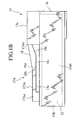
- Locking arm 17A extends from front to rear in receiving chamber 14, and the rear thereof protrudes upward. Front and rear ends 17Aa and 17Ab of locking arm 17A are supported by connector housing 11, which specifies a double support.
- the double support allows locking arm 17A to be difficult to yield, and further enhances the retaining force for terminal 32 exerted by locking part 18 of locking arm 17A. Strong pulling of electric wire 30 rearward allows engagement part 32b of terminal 32 to abut against locking surface 18b of locking part 18 for locking together. This locking prevents terminal 32 from being disconnected and falling from locking part 18 of locking arm 17A.
- one disengagement part 18d is operated by use of fixture 40. This operation can disengage the engagement of locking part 18 with engagement part 32b of terminal 32, which simplifies disengagement work.
- the operation requires single disengagement piece 41 provided to fixture 40 for each terminal receiving chamber. This simplifies the structure of disengagement fixture 40, and reduces manufacturing costs thereof.
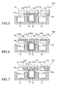
- this connector 10B of a second embodiment includes top board 17Bd formed integrally with flexible locking arm 17B.
- Top board 17Bd covers receiving chamber 14.
- Locking arm 17B and top board 17Bd define a terminal receiving space therebetween. It is possible to receive the upper part of terminal body 32a in the space.
- Other configurations are similar to those of connector 10 of the first embodiment, the same reference numerals are attached to the same constituent parts, and detailed description therefor will be omitted.
- connector 10B it is possible to receive the upper part of terminal body 32a in the terminal receiving space formed between locking arm 17B and top board 17Bd.
- locking surface 18b of locking part 18 locks engagement part 32b of terminal 32, the upper part of terminal body 32a is completely received in the space and held securely.
- any rattling of terminal 32 in receiving chamber 14 is easily and securely controlled. This further enhances the reliability of a connection between terminal 32 and the mating terminal (not shown).
- this connector 10C of a third embodiment includes top board 17Cd formed integrally with the upper end of locking arm 17C.
- Top board 17Cd covers a part of receiving chamber 14. It is possible to receive the upper part of terminal body 32a in a terminal receiving space formed between locking arm 17C and top board 17Cd.
- the fact that terminal receiving chamber 14 is not entirely covered with top board 17Cd enables protrusion 32e protruded on the upper part of terminal body 32a by bending to be received in chamber 14.
- Other configurations are similar to those of connectors 10A and 10B of the first and second embodiments, the same reference numerals are attached to the same constituent parts, and detailed description therefor will be omitted.
- top board 17Cd is formed on locking arm 17C, and protrusion 32e protruded on the upper part of terminal body 32a is receivable in chamber 14.
- Locking surface 18b locks engagement part 32b of terminal 32, and thus the upper part of terminal body 32a can be received completely in the terminal receiving space between locking arm 17C and top board 17Cd and held securely. This can control the rattle of terminal 32 in terminal receiving chamber 14 more easily and securely, and can further enhance the reliability of the connection between terminal 32 and the mating terminal.
- supporting of the first and second portions of the flexible locking arm on the wall allows the locking arm to be difficult to yield, when the locking arm locks with the terminal. This enhances the retaining force for the terminal.
- the locking arm with sufficient retaining force for the terminal allows pitch between terminals to be reduced. This achieves a smaller connector in size.
- the locking part with a relatively simple structure further prevents the locking arm from yielding during locking of the terminal with the locking part. This enhances the retaining force of the locking part against the terminal.
- the supporting of the locking part on the wall further prevents the locking arm from yielding during locking of the terminal with the locking part, which enhances the retaining force of the locking part against the terminal.
- the opening securely prevents the terminal from rattling, which enhances the contact reliability of the terminal with a mating terminal.
- the second top wall retains against the terminal to securely prevent rattling of the terminal, thus enhancing the contact reliability of the terminal with a mating terminal.
- the second top wall retains against the projection of the terminal to securely prevent rattling of the terminal, thus enhancing the contact reliability of the terminal with a mating terminal.
- the operation of the disengagement part allows the locking part and terminal to be disengaged from each other. This simplifies the disengagement operation, and achieves the disengagement operation with a single disengagement fixture, which simplifies the disengagement fixture in structure and reduces production cost.
Landscapes
- Connector Housings Or Holding Contact Members (AREA)
- Details Of Connecting Devices For Male And Female Coupling (AREA)
Claims (8)
- Connecteur comprenant :un boîtier de connecteur (11) ayant des chambres de réception de terminal (14) et des chambres de réception de raccordement par sertissage (15) définies par une paroi, comprenant une première et une seconde parois latérales (13d1, 13d2) et une première paroi supérieure (13a) s'entendant entre elles, et configuré pour insérer et recevoir des terminaux par l'arrière des chambres ; etun bras de verrouillage flexible en saillie (17A) fourni pour chaque chambre de réception du terminal ;caractérisé en ce quele bras de verrouillage flexible est un bras de verrouillage flexible unique (17A) ayant une extrémité avant (17Aa) supportée par la première paroi latérale (13d1) du boîtier de connecteur,le bras de verrouillage flexible a une extrémité arrière (17Ab) supportée par la première paroi supérieure (13a) du boîtier de connecteur,le bras de verrouillage comprend une partie de verrouillage (18) s'étendant de la première paroi latérale (13d1) vers la seconde paroi latérale (13d2) et configuré pour se verrouiller avec la partie d'engagement (32b) d'un terminal, etla partie de verrouillage (18) est supportée par la première paroi supérieure.
- Connecteur selon la revendication 1,
dans lequel le bras flexible (17A) comprend une partie flexible (17Ac) entre les extrémités avant et arrière, et la partie flexible comprend la partie de verrouillage (18). - Connecteur selon la revendication 2,
dans lequel la partie flexible (17Ac) est déformable de manière flexible par rapport à la partie d'engagement (32b) du terminal, et la partie de verrouillage (18) peut être verrouillée avec la partie d'engagement (32b) du terminal reçu dans la chambre. - Connecteur selon la revendication 1,
dans lequel chaque chambre a une ouverture (14a) configurée pour ajuster le terminal (32) dans l'ouverture. - Connecteur selon la revendication 4,
dans lequel l'ouverture (14a) est formée dans un rectangle plan. - Connecteur selon la revendication 4,
dans lequel le bras de verrouillage (17B) comprend une seconde paroi supérieure (17Bd) configurée pour couvrir l'ouverture (14a). - Connecteur selon la revendication 6,
dans lequel le terminal (32) comprend une saillie (32e) couverte par la seconde paroi supérieure (17Cd). - Connecteur selon la revendication 1,
dans lequel la partie de verrouillage (18) comprend une partie de désengagement (18d) pouvant s'engager avec une pièce de désengagement (41) d'un appareil fixe de désengagement (40),
dans lequel la paroi comprend un passage guide (12c) pour conduire la pièce de désengagement (41) à la partie de désengagement (18d), et
dans lequel la pièce de désengagement (41) et la partie de désengagement (18d) s'engagent l'une avec l'autre pour désengager le terminal (32) et la partie de verrouillage (18) l'un de l'autre.
Applications Claiming Priority (2)
| Application Number | Priority Date | Filing Date | Title |
|---|---|---|---|
| JP2002214354A JP3889682B2 (ja) | 2002-07-23 | 2002-07-23 | コネクタ |
| JP2002214354 | 2002-07-23 |
Publications (2)
| Publication Number | Publication Date |
|---|---|
| EP1385235A1 EP1385235A1 (fr) | 2004-01-28 |
| EP1385235B1 true EP1385235B1 (fr) | 2007-06-20 |
Family
ID=29997232
Family Applications (1)
| Application Number | Title | Priority Date | Filing Date |
|---|---|---|---|
| EP03015649A Expired - Lifetime EP1385235B1 (fr) | 2002-07-23 | 2003-07-17 | Connecteur électrique |
Country Status (5)
| Country | Link |
|---|---|
| US (1) | US7108550B2 (fr) |
| EP (1) | EP1385235B1 (fr) |
| JP (1) | JP3889682B2 (fr) |
| KR (1) | KR100540601B1 (fr) |
| DE (1) | DE60314477T2 (fr) |
Families Citing this family (6)
| Publication number | Priority date | Publication date | Assignee | Title |
|---|---|---|---|---|
| JP4498916B2 (ja) | 2004-12-28 | 2010-07-07 | 矢崎総業株式会社 | コネクタ |
| JP4823285B2 (ja) * | 2008-09-19 | 2011-11-24 | タイコエレクトロニクスジャパン合同会社 | 電気コネクタ |
| JP5233822B2 (ja) * | 2009-04-24 | 2013-07-10 | 住友電装株式会社 | 端子金具 |
| KR101039806B1 (ko) * | 2010-09-02 | 2011-06-27 | 주식회사 비앤지 | 도로 중앙분리대에 설치되는 빗물을 이용한 식생구조 |
| JP5723603B2 (ja) * | 2011-01-12 | 2015-05-27 | 矢崎総業株式会社 | コネクタ |
| JP5791003B2 (ja) * | 2011-12-13 | 2015-10-07 | 住友電装株式会社 | コネクタ |
Family Cites Families (7)
| Publication number | Priority date | Publication date | Assignee | Title |
|---|---|---|---|---|
| JPS61218081A (ja) | 1985-03-25 | 1986-09-27 | 矢崎総業株式会社 | 端子の二重係止構造を有するコネクタ |
| JP2957084B2 (ja) * | 1994-04-08 | 1999-10-04 | 矢崎総業株式会社 | コネクタハウジング |
| JPH08321345A (ja) * | 1995-05-24 | 1996-12-03 | Yazaki Corp | コネクタハウジング |
| JP3098934B2 (ja) * | 1995-06-06 | 2000-10-16 | 矢崎総業株式会社 | コネクタ |
| JPH09115644A (ja) * | 1995-10-13 | 1997-05-02 | Yazaki Corp | 端子抜き取り治具およびコネクタハウジング |
| JP3717702B2 (ja) * | 1999-04-23 | 2005-11-16 | 矢崎総業株式会社 | 端子保持構造 |
| JP3495020B2 (ja) | 2000-11-24 | 2004-02-09 | 矢崎総業株式会社 | コネクタ |
-
2002
- 2002-07-23 JP JP2002214354A patent/JP3889682B2/ja not_active Expired - Fee Related
-
2003
- 2003-07-11 US US10/616,976 patent/US7108550B2/en not_active Expired - Lifetime
- 2003-07-17 DE DE60314477T patent/DE60314477T2/de not_active Expired - Lifetime
- 2003-07-17 EP EP03015649A patent/EP1385235B1/fr not_active Expired - Lifetime
- 2003-07-23 KR KR1020030050465A patent/KR100540601B1/ko not_active Expired - Fee Related
Non-Patent Citations (1)
| Title |
|---|
| None * |
Also Published As
| Publication number | Publication date |
|---|---|
| JP3889682B2 (ja) | 2007-03-07 |
| JP2004055466A (ja) | 2004-02-19 |
| KR20040010344A (ko) | 2004-01-31 |
| EP1385235A1 (fr) | 2004-01-28 |
| US7108550B2 (en) | 2006-09-19 |
| DE60314477D1 (de) | 2007-08-02 |
| US20050090161A1 (en) | 2005-04-28 |
| KR100540601B1 (ko) | 2006-01-11 |
| DE60314477T2 (de) | 2008-02-21 |
Similar Documents
| Publication | Publication Date | Title |
|---|---|---|
| US5683272A (en) | Pressure-contact connector | |
| US6638108B2 (en) | Connector with plural housings accommodated in a casing | |
| US7114997B2 (en) | Electrical connector | |
| US5618207A (en) | Retaining method and double-retaining connector therefor | |
| US20040023564A1 (en) | Connector | |
| JP3301329B2 (ja) | コネクタ | |
| EP1560298B1 (fr) | Connecteur cloisonné et montage de connecteurs | |
| KR100939700B1 (ko) | 단자 위치 보장 장치를 구비하는 커넥터 조립체 | |
| US5803756A (en) | Electrical connector with short circuit terminal | |
| JPH0381978A (ja) | 端子係止具付コネクタ | |
| US6068512A (en) | Electrical connector | |
| EP1100156B1 (fr) | Connecteur et son assemblage | |
| EP1351339B1 (fr) | Un connecteur miniaturisé | |
| EP1378968B1 (fr) | Connecteur | |
| KR200216959Y1 (ko) | 더블록크형 커넥터 | |
| EP0503947A2 (fr) | Connecteur électrique | |
| EP1583182B1 (fr) | Connecteur electrique | |
| JP4062250B2 (ja) | コネクタ | |
| US6851987B2 (en) | Connector | |
| EP0902504B1 (fr) | Connecteur avec un élément de verrouillage | |
| EP1385235B1 (fr) | Connecteur électrique | |
| JPH09245869A (ja) | 端子係止具付きコネクタ | |
| US7306486B2 (en) | Connector | |
| US6152783A (en) | Double locking member for a connector | |
| US7001224B2 (en) | Connector with retainer for locking terminal fitings |
Legal Events
| Date | Code | Title | Description |
|---|---|---|---|
| PUAI | Public reference made under article 153(3) epc to a published international application that has entered the european phase |
Free format text: ORIGINAL CODE: 0009012 |
|
| 17P | Request for examination filed |
Effective date: 20030717 |
|
| AK | Designated contracting states |
Kind code of ref document: A1 Designated state(s): AT BE BG CH CY CZ DE DK EE ES FI FR GB GR HU IE IT LI LU MC NL PT RO SE SI SK TR |
|
| AX | Request for extension of the european patent |
Extension state: AL LT LV MK |
|
| 17Q | First examination report despatched |
Effective date: 20040823 |
|
| AKX | Designation fees paid |
Designated state(s): DE FR GB |
|
| GRAP | Despatch of communication of intention to grant a patent |
Free format text: ORIGINAL CODE: EPIDOSNIGR1 |
|
| GRAS | Grant fee paid |
Free format text: ORIGINAL CODE: EPIDOSNIGR3 |
|
| GRAA | (expected) grant |
Free format text: ORIGINAL CODE: 0009210 |
|
| RAP1 | Party data changed (applicant data changed or rights of an application transferred) |
Owner name: YAZAKI CORPORATION |
|
| AK | Designated contracting states |
Kind code of ref document: B1 Designated state(s): DE FR GB |
|
| REG | Reference to a national code |
Ref country code: GB Ref legal event code: FG4D |
|
| REF | Corresponds to: |
Ref document number: 60314477 Country of ref document: DE Date of ref document: 20070802 Kind code of ref document: P |
|
| ET | Fr: translation filed | ||
| PLBE | No opposition filed within time limit |
Free format text: ORIGINAL CODE: 0009261 |
|
| STAA | Information on the status of an ep patent application or granted ep patent |
Free format text: STATUS: NO OPPOSITION FILED WITHIN TIME LIMIT |
|
| 26N | No opposition filed |
Effective date: 20080325 |
|
| REG | Reference to a national code |
Ref country code: FR Ref legal event code: PLFP Year of fee payment: 14 |
|
| REG | Reference to a national code |
Ref country code: FR Ref legal event code: PLFP Year of fee payment: 15 |
|
| REG | Reference to a national code |
Ref country code: FR Ref legal event code: PLFP Year of fee payment: 16 |
|
| PGFP | Annual fee paid to national office [announced via postgrant information from national office to epo] |
Ref country code: FR Payment date: 20200611 Year of fee payment: 18 |
|
| PGFP | Annual fee paid to national office [announced via postgrant information from national office to epo] |
Ref country code: DE Payment date: 20200707 Year of fee payment: 18 Ref country code: GB Payment date: 20200708 Year of fee payment: 18 |
|
| REG | Reference to a national code |
Ref country code: DE Ref legal event code: R119 Ref document number: 60314477 Country of ref document: DE |
|
| GBPC | Gb: european patent ceased through non-payment of renewal fee |
Effective date: 20210717 |
|
| PG25 | Lapsed in a contracting state [announced via postgrant information from national office to epo] |
Ref country code: GB Free format text: LAPSE BECAUSE OF NON-PAYMENT OF DUE FEES Effective date: 20210717 Ref country code: DE Free format text: LAPSE BECAUSE OF NON-PAYMENT OF DUE FEES Effective date: 20220201 |
|
| PG25 | Lapsed in a contracting state [announced via postgrant information from national office to epo] |
Ref country code: FR Free format text: LAPSE BECAUSE OF NON-PAYMENT OF DUE FEES Effective date: 20210731 |