EP1385238A2 - Anordnung für die elektrische Kontaktierung von Kaltkathodenröhren - Google Patents
Anordnung für die elektrische Kontaktierung von Kaltkathodenröhren Download PDFInfo
- Publication number
- EP1385238A2 EP1385238A2 EP03464001A EP03464001A EP1385238A2 EP 1385238 A2 EP1385238 A2 EP 1385238A2 EP 03464001 A EP03464001 A EP 03464001A EP 03464001 A EP03464001 A EP 03464001A EP 1385238 A2 EP1385238 A2 EP 1385238A2
- Authority
- EP
- European Patent Office
- Prior art keywords
- thread
- clearance
- cover
- electrode
- cold cathode
- Prior art date
- Legal status (The legal status is an assumption and is not a legal conclusion. Google has not performed a legal analysis and makes no representation as to the accuracy of the status listed.)
- Granted
Links
Images

Classifications
-
- H—ELECTRICITY
- H01—ELECTRIC ELEMENTS
- H01R—ELECTRICALLY-CONDUCTIVE CONNECTIONS; STRUCTURAL ASSOCIATIONS OF A PLURALITY OF MUTUALLY-INSULATED ELECTRICAL CONNECTING ELEMENTS; COUPLING DEVICES; CURRENT COLLECTORS
- H01R33/00—Coupling devices specially adapted for supporting apparatus and having one part acting as a holder providing support and electrical connection via a counterpart which is structurally associated with the apparatus, e.g. lamp holders; Separate parts thereof
- H01R33/02—Single-pole devices, e.g. holder for supporting one end of a tubular incandescent or neon lamp
-
- H—ELECTRICITY
- H01—ELECTRIC ELEMENTS
- H01R—ELECTRICALLY-CONDUCTIVE CONNECTIONS; STRUCTURAL ASSOCIATIONS OF A PLURALITY OF MUTUALLY-INSULATED ELECTRICAL CONNECTING ELEMENTS; COUPLING DEVICES; CURRENT COLLECTORS
- H01R4/00—Electrically-conductive connections between two or more conductive members in direct contact, i.e. touching one another; Means for effecting or maintaining such contact; Electrically-conductive connections having two or more spaced connecting locations for conductors and using contact members penetrating insulation
- H01R4/28—Clamped connections, spring connections
- H01R4/30—Clamped connections, spring connections utilising a screw or nut clamping member
Definitions
- the invention relates to an electrical connection device for discharge tubes with cold cathode.
- cold cathode discharge tubes which include a sealed tube in glass and metal cages at the ends, to initiate and maintain the electric shock.
- the cage is provided with a metallic connection electrode which passes tightly through the glass tube by a glass prominence.
- connection of the tube is made by twisting part of the stripped end of the electrical cable, with the outer end of the metal electrode and the insulation of the connection thus obtained.
- This connection mode is not safe, because the twist does not resist for a long time and the electrical contact is affected by oxidation.
- Another known electrical connection device [inventions EP 0911915 and EP 1067631] has an axial channel through which the outer electrode of the tube and a rod pass radial threaded to fix the electrode.
- This terminal has the disadvantage that the threaded rod radial has too small a diameter and does not allow a satisfactory tightening. The tightening weakened over the time and we have difficulties with manual operations, because of the too small dimensions of the radial threaded rod.
- invention FR 2769752 has an axial channel, through which the electrode passes of the tube, as well as, on the other end, part of the electrical power cable, which is tightened together with a radial threaded rod.
- a variant of this system provides for another channel perpendicular to the axial channel, through which the electrode of the tube is passed. Through the same channel we introduces the power supply cable. We tighten the electrode and the two conductors with a axial threaded rod. This system has the disadvantage of inconvenient handling.
- the electrical connection device for cold cathode discharge tubes comprises a sealed glass tube and metal cages at the ends, to initiate and maintain the electrical discharge, provided with a metal connection electrode, which sealingly passes through the glass tube , by a glass prominence and which is supplied by an electric power cable , eliminates the disadvantages already mentioned, because it is composed of a support piece of the metal connection electrode, which has the shape of a glass and which has at the base an axial orifice to pass the metal connection electrode, the inner edge of the opening of the support part has a clearance for installation on the sealed glass tube, opposite the opening, at the exterior, the support piece having a thread, a connecting piece for fixing the connection electrode, composed of a cover which has an inside thread and a clearance from the inside edge from the cover to the beginning of the internal thread, outside the base of the cover, the fixing part, having an empty cylinder, which has an external thread and a clearance in contact with the thread on the outer surface of the bottom cover and, tangent to the outer surface of the bottom of the cover, the cylinder is
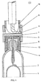
- the known cold cathode discharge luminescent tube is composed of a sealed glass tube 1, which has metal cages 2 at the ends to initiate and maintain the electrical discharge.
- the metal cage 2 is provided with a metal connection electrode 3, which crosses the tube 1 tightly, through a glass prominence 4.
- An electric power cable 5 is connected to the metal electrode 3.
- the electrical connection device for cold cathode discharge tubes is composed of a support part 6 of the metal connection electrode 3, of a part 7 for fixing the connection electrode 3 and a hooking nut 8 of the electric supply cable 5.
- the support part 6 of the metal connection electrode 3 has the form of a glass and has at the base an axial orifice 9 so that the metal electrode 3 can be passed.
- the inner edge of the opening of the support piece 6 has a clearance 10, for fitting on the sealed glass tube 1.
- a thread 11 At the other end of the opening, outside of the support piece 6, there is a thread 11.
- the outer surface of the support piece 6, between the thread and the opening of the piece, is machined with roughness, striated or profiled for easy handling, manually or using specialized tools or instruments.
- the glass protrusion 4 is introduced into the support part 6 and the metal connection electrode 3, passes through the axial orifice 9 and it is bent at right angles, above the external surface of the base of the part. .
- the support part 6 of the metal electrode 3 is supported by the release 10 on the glass tube and it is rigidly fixed to the latter and to the glass prominence 4 by an adhesive 12, introduced inside.
- the part 7 for fixing the connection electrode 3 is metallic and it is composed of a cover 13, which has an internal thread 14 and a clearance 15 from the internal edge of the cover until the beginning of the internal thread 14.
- the outer surface of the cover 13 is machined with roughness, ridged or profiled for easy handling, manually or using tools or specialized instruments.
- the cover 13 is threaded on the support part 6 of the electrode and electrical contact is made with the metal connection electrode 3 by tightening and also the fixing thereof.
- the clearance 15 coats part of the support part 6 and provides protection against the penetration of undesirable substances into the contact zone.
- a bonding paste is put on the internal thread 14 of the cover 7, in the area of the clearance 15 and on the external thread 11 of the support part 6, which hardens, producing a sealing and thus protection of the electrical contact and also protection against the loosening of parts, vibrations or other unforeseen causes.
- the fastening part 7 On the outside of the base of the cover 13, the fastening part 7 has an empty cylinder 16, which has an external thread 17 and a clearance at the contact zone between the thread and the external surface of the bottom of the cover 13. Tangent on the outer surface of the bottom of the cover 13, the cylinder 16 is crossed by a channel 18 .
- the hooking nut 8 of the electric supply cable 5 a at one of the ends of the net, clearance 19.
- the outer surface of the hooking nut 8 of the electric cable 5 feed is machined with roughness, ridged or profiled for easy handling, manually where using tools where specialized instruments ,.
- the hooking nut 8 of the electric supply cable 5 is threaded on the cylinder 16, with the clearance 19 outwards.
- the edge of the cylinder 16, including the outer thread 17, is deformed, slightly enlarged, as well as the hooking nut 8, remains captive, the deformation mentioned entering, when the nut is completely loose, in clearance 19. In the loosened position, the nut completely releases the channel 18.
Landscapes
- Common Detailed Techniques For Electron Tubes Or Discharge Tubes (AREA)
- Vessels And Coating Films For Discharge Lamps (AREA)
- Cold Cathode And The Manufacture (AREA)
Applications Claiming Priority (2)
| Application Number | Priority Date | Filing Date | Title |
|---|---|---|---|
| ROA200201025A RO119977B1 (ro) | 2002-07-25 | 2002-07-25 | Soclu electrod pentru lămpi cu descărcare în gaze spectrale |
| RO201000025 | 2002-07-25 |
Publications (3)
| Publication Number | Publication Date |
|---|---|
| EP1385238A2 true EP1385238A2 (de) | 2004-01-28 |
| EP1385238A3 EP1385238A3 (de) | 2005-01-05 |
| EP1385238B1 EP1385238B1 (de) | 2007-02-14 |
Family
ID=29997636
Family Applications (1)
| Application Number | Title | Priority Date | Filing Date |
|---|---|---|---|
| EP03464001A Expired - Lifetime EP1385238B1 (de) | 2002-07-25 | 2003-07-23 | Anordnung für die elektrische Kontaktierung von Kaltkathodenröhren |
Country Status (4)
| Country | Link |
|---|---|
| EP (1) | EP1385238B1 (de) |
| AT (1) | ATE354193T1 (de) |
| DE (1) | DE60311711D1 (de) |
| RO (1) | RO119977B1 (de) |
Cited By (1)
| Publication number | Priority date | Publication date | Assignee | Title |
|---|---|---|---|---|
| WO2010015946A1 (en) | 2008-08-07 | 2010-02-11 | Tyco Electronics Amp Italia S.P.A. | Connector device for connecting a cold cathode of a neon or fluorescent-tube lamp to a supply cable |
Family Cites Families (2)
| Publication number | Priority date | Publication date | Assignee | Title |
|---|---|---|---|---|
| GB662994A (en) * | 1949-05-26 | 1951-12-12 | Ozalid Co Ltd | An improved end connection for tubular electric lamps |
| US5045000A (en) * | 1990-07-09 | 1991-09-03 | Everbrite, Inc. | Neon sign connector |
-
2002
- 2002-07-25 RO ROA200201025A patent/RO119977B1/ro unknown
-
2003
- 2003-07-23 AT AT03464001T patent/ATE354193T1/de not_active IP Right Cessation
- 2003-07-23 EP EP03464001A patent/EP1385238B1/de not_active Expired - Lifetime
- 2003-07-23 DE DE60311711T patent/DE60311711D1/de not_active Expired - Lifetime
Cited By (3)
| Publication number | Priority date | Publication date | Assignee | Title |
|---|---|---|---|---|
| WO2010015946A1 (en) | 2008-08-07 | 2010-02-11 | Tyco Electronics Amp Italia S.P.A. | Connector device for connecting a cold cathode of a neon or fluorescent-tube lamp to a supply cable |
| CN102113184A (zh) * | 2008-08-07 | 2011-06-29 | 泰科电子Amp意大利公司 | 用于将氖或者荧光管灯连接到电源电缆的连接器装置 |
| EP2311156B1 (de) * | 2008-08-07 | 2016-07-06 | Tyco Electronics AMP Italia S.p.A. | Steckverbindervorrichtung zum anschluss einer kalten kathode einer neon- oder fluoreszenzleuchte an ein versorgungskabel |
Also Published As
| Publication number | Publication date |
|---|---|
| ATE354193T1 (de) | 2007-03-15 |
| EP1385238B1 (de) | 2007-02-14 |
| EP1385238A3 (de) | 2005-01-05 |
| RO119977B1 (ro) | 2005-06-30 |
| DE60311711D1 (de) | 2007-03-29 |
Similar Documents
| Publication | Publication Date | Title |
|---|---|---|
| US7705240B2 (en) | Cord seal for swimming pool and spa light niches | |
| EP1376766B1 (de) | Befestigungsanordnung einer elektrischen Anschlussklemme | |
| EP1385238A2 (de) | Anordnung für die elektrische Kontaktierung von Kaltkathodenröhren | |
| EP0691262A1 (de) | Spritzschutz für Fahrräder und Herstellungsverfahren | |
| EP2355248A1 (de) | Drahtklemmvorrichtung | |
| FR2824603A1 (fr) | Dispositif de serrage | |
| EP1842271A1 (de) | Wandelement für abgedichteten kabeldurchgang | |
| FR2704467A1 (fr) | Elément de raccordement pour l'alimentation des équipements de soudage ou de découpage à arc électrique. | |
| FR2763654A1 (fr) | Insert pour la fixation d'une cosse de raccordement electrique sur une paroi mince, et ses procedes de montage et de demontage | |
| US20020068472A1 (en) | Externally threaded conduit body for compression connection | |
| FR2496220A1 (fr) | Raccord a emboitement et son procede de montage | |
| FR2562984A1 (fr) | Raccord de securite pour circuits pneumatiques | |
| KR200196182Y1 (ko) | 송전선 고정용 압축인류클램프 | |
| EP0821835A1 (de) | Hinterverbindungsvorrichtung für elektrischen stecker für abgeschirmtes kabel | |
| FR2810457A1 (fr) | Connecteur pour connexion rapide d'un cable a une electrode a cathode froide | |
| FR2894721A1 (fr) | Etrier de serrage a vis imperdable pour raccorder deux conducteurs | |
| FR3021683A1 (fr) | Suspente pour l'accrochage d'un rail de fixation d'un element de doublage en combinaison avec un materiau isolant et une membrane d'etancheite | |
| KR100687340B1 (ko) | 와이어 접속 장치 | |
| JPH08166046A (ja) | ワイヤ緊張装置 | |
| KR970004489Y1 (ko) | 전화선 고정구 | |
| JPH09163579A (ja) | 分岐線引出部 | |
| EP2460231A1 (de) | Verbinder oder verbindungsklemme für beschichtete oberleitungskabel | |
| FR2471057A1 (fr) | Bride d'accouplement pour antenne et antenne ainsi equipee | |
| KR200156698Y1 (ko) | 가공지선 지지대 | |
| FR2520087A1 (fr) | Dispositif pour faciliter le raccordement des tuyaux onduleux et procede pour le realiser |
Legal Events
| Date | Code | Title | Description |
|---|---|---|---|
| PUAI | Public reference made under article 153(3) epc to a published international application that has entered the european phase |
Free format text: ORIGINAL CODE: 0009012 |
|
| AK | Designated contracting states |
Kind code of ref document: A2 Designated state(s): AT BE BG CH CY CZ DE DK EE ES FI FR GB GR HU IE IT LI LU MC NL PT RO SE SI SK TR |
|
| AX | Request for extension of the european patent |
Extension state: AL LT LV MK |
|
| PUAL | Search report despatched |
Free format text: ORIGINAL CODE: 0009013 |
|
| AK | Designated contracting states |
Kind code of ref document: A3 Designated state(s): AT BE BG CH CY CZ DE DK EE ES FI FR GB GR HU IE IT LI LU MC NL PT RO SE SI SK TR |
|
| AX | Request for extension of the european patent |
Extension state: AL LT LV MK |
|
| 17P | Request for examination filed |
Effective date: 20050525 |
|
| AKX | Designation fees paid |
Designated state(s): AT BE BG CH CY CZ DE DK EE ES FI FR GB GR HU IE IT LI LU MC NL PT RO SE SI SK TR |
|
| GRAP | Despatch of communication of intention to grant a patent |
Free format text: ORIGINAL CODE: EPIDOSNIGR1 |
|
| GRAS | Grant fee paid |
Free format text: ORIGINAL CODE: EPIDOSNIGR3 |
|
| GRAA | (expected) grant |
Free format text: ORIGINAL CODE: 0009210 |
|
| AK | Designated contracting states |
Kind code of ref document: B1 Designated state(s): AT BE BG CH CY CZ DE DK EE ES FI FR GB GR HU IE IT LI LU MC NL PT RO SE SI SK TR |
|
| PG25 | Lapsed in a contracting state [announced via postgrant information from national office to epo] |
Ref country code: SI Free format text: LAPSE BECAUSE OF FAILURE TO SUBMIT A TRANSLATION OF THE DESCRIPTION OR TO PAY THE FEE WITHIN THE PRESCRIBED TIME-LIMIT Effective date: 20070214 Ref country code: DK Free format text: LAPSE BECAUSE OF FAILURE TO SUBMIT A TRANSLATION OF THE DESCRIPTION OR TO PAY THE FEE WITHIN THE PRESCRIBED TIME-LIMIT Effective date: 20070214 Ref country code: NL Free format text: LAPSE BECAUSE OF FAILURE TO SUBMIT A TRANSLATION OF THE DESCRIPTION OR TO PAY THE FEE WITHIN THE PRESCRIBED TIME-LIMIT Effective date: 20070214 Ref country code: FI Free format text: LAPSE BECAUSE OF FAILURE TO SUBMIT A TRANSLATION OF THE DESCRIPTION OR TO PAY THE FEE WITHIN THE PRESCRIBED TIME-LIMIT Effective date: 20070214 Ref country code: AT Free format text: LAPSE BECAUSE OF FAILURE TO SUBMIT A TRANSLATION OF THE DESCRIPTION OR TO PAY THE FEE WITHIN THE PRESCRIBED TIME-LIMIT Effective date: 20070214 Ref country code: IE Free format text: LAPSE BECAUSE OF FAILURE TO SUBMIT A TRANSLATION OF THE DESCRIPTION OR TO PAY THE FEE WITHIN THE PRESCRIBED TIME-LIMIT Effective date: 20070214 |
|
| REG | Reference to a national code |
Ref country code: GB Ref legal event code: FG4D Free format text: NOT ENGLISH |
|
| REG | Reference to a national code |
Ref country code: CH Ref legal event code: EP |
|
| REF | Corresponds to: |
Ref document number: 60311711 Country of ref document: DE Date of ref document: 20070329 Kind code of ref document: P |
|
| REG | Reference to a national code |
Ref country code: IE Ref legal event code: FG4D Free format text: LANGUAGE OF EP DOCUMENT: FRENCH |
|
| PG25 | Lapsed in a contracting state [announced via postgrant information from national office to epo] |
Ref country code: SE Free format text: LAPSE BECAUSE OF FAILURE TO SUBMIT A TRANSLATION OF THE DESCRIPTION OR TO PAY THE FEE WITHIN THE PRESCRIBED TIME-LIMIT Effective date: 20070514 |
|
| PG25 | Lapsed in a contracting state [announced via postgrant information from national office to epo] |
Ref country code: BG Free format text: LAPSE BECAUSE OF EXPIRATION OF PROTECTION Effective date: 20070515 |
|
| PG25 | Lapsed in a contracting state [announced via postgrant information from national office to epo] |
Ref country code: ES Free format text: LAPSE BECAUSE OF FAILURE TO SUBMIT A TRANSLATION OF THE DESCRIPTION OR TO PAY THE FEE WITHIN THE PRESCRIBED TIME-LIMIT Effective date: 20070525 |
|
| PG25 | Lapsed in a contracting state [announced via postgrant information from national office to epo] |
Ref country code: PT Free format text: LAPSE BECAUSE OF FAILURE TO SUBMIT A TRANSLATION OF THE DESCRIPTION OR TO PAY THE FEE WITHIN THE PRESCRIBED TIME-LIMIT Effective date: 20070716 |
|
| NLV1 | Nl: lapsed or annulled due to failure to fulfill the requirements of art. 29p and 29m of the patents act | ||
| GBT | Gb: translation of ep patent filed (gb section 77(6)(a)/1977) |
Effective date: 20070720 |
|
| REG | Reference to a national code |
Ref country code: IE Ref legal event code: FD4D |
|
| PG25 | Lapsed in a contracting state [announced via postgrant information from national office to epo] |
Ref country code: SK Free format text: LAPSE BECAUSE OF FAILURE TO SUBMIT A TRANSLATION OF THE DESCRIPTION OR TO PAY THE FEE WITHIN THE PRESCRIBED TIME-LIMIT Effective date: 20070214 |
|
| PLBE | No opposition filed within time limit |
Free format text: ORIGINAL CODE: 0009261 |
|
| STAA | Information on the status of an ep patent application or granted ep patent |
Free format text: STATUS: NO OPPOSITION FILED WITHIN TIME LIMIT |
|
| PG25 | Lapsed in a contracting state [announced via postgrant information from national office to epo] |
Ref country code: CZ Free format text: LAPSE BECAUSE OF FAILURE TO SUBMIT A TRANSLATION OF THE DESCRIPTION OR TO PAY THE FEE WITHIN THE PRESCRIBED TIME-LIMIT Effective date: 20070214 Ref country code: RO Free format text: LAPSE BECAUSE OF FAILURE TO SUBMIT A TRANSLATION OF THE DESCRIPTION OR TO PAY THE FEE WITHIN THE PRESCRIBED TIME-LIMIT Effective date: 20070214 |
|
| 26N | No opposition filed |
Effective date: 20071115 |
|
| PG25 | Lapsed in a contracting state [announced via postgrant information from national office to epo] |
Ref country code: DE Free format text: LAPSE BECAUSE OF FAILURE TO SUBMIT A TRANSLATION OF THE DESCRIPTION OR TO PAY THE FEE WITHIN THE PRESCRIBED TIME-LIMIT Effective date: 20070515 |
|
| REG | Reference to a national code |
Ref country code: CH Ref legal event code: PL |
|
| PG25 | Lapsed in a contracting state [announced via postgrant information from national office to epo] |
Ref country code: CH Free format text: LAPSE BECAUSE OF NON-PAYMENT OF DUE FEES Effective date: 20070731 Ref country code: LI Free format text: LAPSE BECAUSE OF NON-PAYMENT OF DUE FEES Effective date: 20070731 Ref country code: IT Free format text: LAPSE BECAUSE OF FAILURE TO SUBMIT A TRANSLATION OF THE DESCRIPTION OR TO PAY THE FEE WITHIN THE PRESCRIBED TIME-LIMIT Effective date: 20070214 Ref country code: GR Free format text: LAPSE BECAUSE OF FAILURE TO SUBMIT A TRANSLATION OF THE DESCRIPTION OR TO PAY THE FEE WITHIN THE PRESCRIBED TIME-LIMIT Effective date: 20070515 Ref country code: MC Free format text: LAPSE BECAUSE OF NON-PAYMENT OF DUE FEES Effective date: 20070731 |
|
| PG25 | Lapsed in a contracting state [announced via postgrant information from national office to epo] |
Ref country code: EE Free format text: LAPSE BECAUSE OF FAILURE TO SUBMIT A TRANSLATION OF THE DESCRIPTION OR TO PAY THE FEE WITHIN THE PRESCRIBED TIME-LIMIT Effective date: 20070214 |
|
| REG | Reference to a national code |
Ref country code: FR Ref legal event code: ST Effective date: 20090331 |
|
| REG | Reference to a national code |
Ref country code: FR Ref legal event code: RN |
|
| PG25 | Lapsed in a contracting state [announced via postgrant information from national office to epo] |
Ref country code: CY Free format text: LAPSE BECAUSE OF FAILURE TO SUBMIT A TRANSLATION OF THE DESCRIPTION OR TO PAY THE FEE WITHIN THE PRESCRIBED TIME-LIMIT Effective date: 20070214 |
|
| PGFP | Annual fee paid to national office [announced via postgrant information from national office to epo] |
Ref country code: BE Payment date: 20090102 Year of fee payment: 6 |
|
| PG25 | Lapsed in a contracting state [announced via postgrant information from national office to epo] |
Ref country code: LU Free format text: LAPSE BECAUSE OF NON-PAYMENT OF DUE FEES Effective date: 20070723 Ref country code: FR Free format text: LAPSE BECAUSE OF NON-PAYMENT OF DUE FEES Effective date: 20080731 |
|
| PG25 | Lapsed in a contracting state [announced via postgrant information from national office to epo] |
Ref country code: TR Free format text: LAPSE BECAUSE OF FAILURE TO SUBMIT A TRANSLATION OF THE DESCRIPTION OR TO PAY THE FEE WITHIN THE PRESCRIBED TIME-LIMIT Effective date: 20070214 Ref country code: HU Free format text: LAPSE BECAUSE OF FAILURE TO SUBMIT A TRANSLATION OF THE DESCRIPTION OR TO PAY THE FEE WITHIN THE PRESCRIBED TIME-LIMIT Effective date: 20070815 |
|
| REG | Reference to a national code |
Ref country code: FR Ref legal event code: FC |
|
| BERE | Be: lapsed |
Owner name: SC IANLUX SRL Effective date: 20090731 |
|
| PGRI | Patent reinstated in contracting state [announced from national office to epo] |
Ref country code: FR Effective date: 20100114 |
|
| PG25 | Lapsed in a contracting state [announced via postgrant information from national office to epo] |
Ref country code: BE Free format text: LAPSE BECAUSE OF NON-PAYMENT OF DUE FEES Effective date: 20090731 |
|
| REG | Reference to a national code |
Ref country code: FR Ref legal event code: PLFP Year of fee payment: 14 |
|
| PGFP | Annual fee paid to national office [announced via postgrant information from national office to epo] |
Ref country code: FR Payment date: 20160708 Year of fee payment: 14 |
|
| PGFP | Annual fee paid to national office [announced via postgrant information from national office to epo] |
Ref country code: GB Payment date: 20170719 Year of fee payment: 15 |
|
| REG | Reference to a national code |
Ref country code: FR Ref legal event code: ST Effective date: 20180330 |
|
| PG25 | Lapsed in a contracting state [announced via postgrant information from national office to epo] |
Ref country code: FR Free format text: LAPSE BECAUSE OF NON-PAYMENT OF DUE FEES Effective date: 20170731 |
|
| GBPC | Gb: european patent ceased through non-payment of renewal fee |
Effective date: 20180723 |
|
| PG25 | Lapsed in a contracting state [announced via postgrant information from national office to epo] |
Ref country code: GB Free format text: LAPSE BECAUSE OF NON-PAYMENT OF DUE FEES Effective date: 20180723 |