EP1385263A2 - Commande d'entraínement à reluctance commutée - Google Patents
Commande d'entraínement à reluctance commutée Download PDFInfo
- Publication number
- EP1385263A2 EP1385263A2 EP03254563A EP03254563A EP1385263A2 EP 1385263 A2 EP1385263 A2 EP 1385263A2 EP 03254563 A EP03254563 A EP 03254563A EP 03254563 A EP03254563 A EP 03254563A EP 1385263 A2 EP1385263 A2 EP 1385263A2
- Authority
- EP
- European Patent Office
- Prior art keywords
- current
- phase winding
- signal
- phase
- rotor
- Prior art date
- Legal status (The legal status is an assumption and is not a legal conclusion. Google has not performed a legal analysis and makes no representation as to the accuracy of the status listed.)
- Withdrawn
Links
- 238000004804 winding Methods 0.000 claims abstract description 83
- 238000000034 method Methods 0.000 claims description 24
- 230000007704 transition Effects 0.000 abstract description 8
- 230000008901 benefit Effects 0.000 description 3
- 239000003990 capacitor Substances 0.000 description 3
- 230000004907 flux Effects 0.000 description 3
- 230000009471 action Effects 0.000 description 2
- 230000008859 change Effects 0.000 description 2
- 230000007423 decrease Effects 0.000 description 2
- 230000001419 dependent effect Effects 0.000 description 2
- 238000001514 detection method Methods 0.000 description 2
- 238000011084 recovery Methods 0.000 description 2
- 230000035945 sensitivity Effects 0.000 description 2
- 230000001052 transient effect Effects 0.000 description 2
- 230000005534 acoustic noise Effects 0.000 description 1
- 230000009286 beneficial effect Effects 0.000 description 1
- 230000010485 coping Effects 0.000 description 1
- 230000003247 decreasing effect Effects 0.000 description 1
- 230000000694 effects Effects 0.000 description 1
- 238000005259 measurement Methods 0.000 description 1
- 230000004048 modification Effects 0.000 description 1
- 238000012986 modification Methods 0.000 description 1
- 230000003287 optical effect Effects 0.000 description 1
- 230000010355 oscillation Effects 0.000 description 1
- 230000009467 reduction Effects 0.000 description 1
- 230000004044 response Effects 0.000 description 1
- 230000003019 stabilising effect Effects 0.000 description 1
Images


Classifications
-
- H—ELECTRICITY
- H02—GENERATION; CONVERSION OR DISTRIBUTION OF ELECTRIC POWER
- H02P—CONTROL OR REGULATION OF ELECTRIC MOTORS, ELECTRIC GENERATORS OR DYNAMO-ELECTRIC CONVERTERS; CONTROLLING TRANSFORMERS, REACTORS OR CHOKE COILS
- H02P25/00—Arrangements or methods for the control of AC motors characterised by the kind of AC motor or by structural details
- H02P25/02—Arrangements or methods for the control of AC motors characterised by the kind of AC motor or by structural details characterised by the kind of motor
- H02P25/08—Reluctance motors
- H02P25/092—Converters specially adapted for controlling reluctance motors
- H02P25/0925—Converters specially adapted for controlling reluctance motors wherein the converter comprises only one switch per phase
-
- H—ELECTRICITY
- H02—GENERATION; CONVERSION OR DISTRIBUTION OF ELECTRIC POWER
- H02P—CONTROL OR REGULATION OF ELECTRIC MOTORS, ELECTRIC GENERATORS OR DYNAMO-ELECTRIC CONVERTERS; CONTROLLING TRANSFORMERS, REACTORS OR CHOKE COILS
- H02P25/00—Arrangements or methods for the control of AC motors characterised by the kind of AC motor or by structural details
- H02P25/02—Arrangements or methods for the control of AC motors characterised by the kind of AC motor or by structural details characterised by the kind of motor
- H02P25/08—Reluctance motors
Definitions
- This invention relates to the control of reluctance machines, particularly of switched reluctance machines.
- a typical prior art drive is shown schematically in Figure 1.
- This includes a DC power supply 11 that can be either a battery or rectified and filtered AC mains.
- the DC voltage provided by the power supply 11 is switched across phase windings 16 of the motor 12 by a power converter 13 under the control of the electronic control unit 14.
- Some form of current transducer 18 is normally provided to give phase current feedback.
- Figure 2 One of the many known converter topologies is shown in Figure 2, where a resistor 28 is connected in series with the lower switch 22 to provide a current feedback signal.
- the performance of a switched reluctance machine depends, in part, on the accurate timing of phase energisation with respect to rotor position. Detection of rotor position is conventionally achieved by using a transducer 15, shown schematically in Figure 1, such as a rotating toothed disk mounted on the machine rotor, which co-operates with an optical or magnetic sensor mounted on the stator. A pulse train indicative of rotor position relative to the stator is generated and supplied to control circuitry, allowing accurate phase energisation.
- Alternative methods of position detection include the so-called "sensorless" methods, in which the position is deduced from measurements of another parameter of the machine.
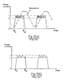
- switched reluctance systems generally operate in a current-controlled or "chopping" mode, as illustrated generally in Figure 3 for motoring.
- a hysteresis current controller using "hard” chopping is often used, as shown in Figure 3(a).
- the voltage is applied to the phase at an angle ⁇ on in the minimum inductance region and the current rises rapidly till an upper bound I u is reached, whereupon the switches are opened and the full reverse voltage is applied across the winding by the action of the diodes 23,24, driving down the flux and hence the current.
- the switches are then closed and the current rises again.
- the cycle is repeated until the switch-off angle ⁇ off is reached, typically at the point of maximum inductance when the rotor poles are fully aligned with the stator poles.
- the current is then forced down to zero by the reverse voltage.
- the current remains at zero until the cycle begins again at ⁇ on , so the mark:space ratio of the current is approximately 0.5.
- FIG. 3(b) An alternative regime, known as "soft" chopping, is illustrated in Figure 3(b) in which only one switch, e.g. switch 21, is opened when the current reaches its upper bound, the current then decaying much more slowly through the winding, the second switch 22 and one diode 24.
- the resulting reduction in switching frequency is often beneficial in reducing switching loss in the switches and reducing acoustic noise.
- Other types of current controllers are well known in the art, for example off-time controllers, constant frequency controllers, etc., and will not be described here. Their common characteristic, however, is that they all limit the current to a safe level to prevent damage to the switches and/or the machine.
- switched reluctance systems typically operate in the "single-pulse" mode of energisation.
- This mode is illustrated in Figure 4 in which the current and linearised inductance waveforms are shown over a phase inductance period.
- the current rises when the voltage is applied to the phase winding at the switch-on angle ⁇ on , reaches a peak and then rolls over as the rotor poles begin to overlap the stator poles and the inductance rises.
- the current is limited naturally by the back emf of the circuit.
- the voltage is reversed at ⁇ off and the current falls at a faster rate as energy is returned to the supply and ceases when it reaches zero. There is then a period of zero current before the cycle begins again.
- a special mode of operation of switched reluctance machines is the continuous current mode, as disclosed in US Patent No. 5469039 (Stephenson) and incorporated herein by reference.
- the winding is re-connected to the supply before the flux, and hence the current, have returned to zero at the end of the energy return period.
- the phase windings therefore operate with current continuously flowing through them and are always linked by flux.
- US 5469039 discloses a method of operating in a stable manner in this region so that steady state operation is possible.
- Figure 6 shows a steady-state current waveform in motoring, where the current variation is quasi-sinusoidal above a "standing" value I s . This is an important mode for systems which have to produce high levels of overload output at some points of their operating cycle. Although the efficiency of the drive falls in this mode, it allows specifications to be achieved which would otherwise require a larger machine.
- the parameters of ⁇ on , ⁇ off , I u , I 1, ⁇ f , etc. are generally functions of speed and are either computed in real time or, more commonly, stored in some form of table from which they can be read at appropriate times.
- the parameter values are carefully chosen in order to achieve smooth output from the machine as the speed changes. If the stored values are relatively sparse, some form of interpolation is used to give suitable parameter values at intermediate speeds. There is a particular difficulty in choosing values at the transition points between chopping and single-pulse modes, and between single-pulse and continuous current modes, where a smooth transition is desired regardless of the torque level demanded.
- variable speed drive systems have to operate over a range of supply voltages and in some cases, (typically those drives operating in remote areas or from an isolated power source), that range is a very significant fraction of the nominal supply voltage. While this is generally not a serious difficulty for switched reluctance systems in the chopping mode (since the current controller is generally capable of coping with the changing current gradients), it becomes a problem in single-pulse and continuous current modes, where the torque is strongly dependent on the supply voltage.
- Known attempts to solve this problem include the storing of a complete set of control parameters for a range of supply voltages (i.e. introducing a further parameter, supply voltage, into the set), but this often creates unacceptable demands on storage space in the controller.
- the developed torque is largely independent of the winding resistance (except perhaps in the smallest of machines or those operating at very low voltages).
- the winding temperature, and hence winding resistance changes but the output of the machine is effectively independent, thus allowing the use of control parameters which are unaffected by winding resistance.
- the current is a strong function of the system resistance so, for given control parameters, the output fluctuates with the thermal state of the winding. Even if reliable thermal feedback from the winding were available at a reasonable cost, providing control parameters which compensated for temperature would place an unacceptable burden on storage in the controller.
- a switched reluctance machine in continuous current mode of operation comprising a rotor having a plurality of poles, a stator having a plurality of poles and at least one phase winding, the method comprising:
- phase winding freewheels for at least part of the remainder of the conduction angle of the phase winding. In the motoring mode this tends to control the standing current in the phase winding and in generating mode this tends to control the output voltage of the machine.
- the method may also comprise generating a third signal, which third signal causes reversal of the voltage on the phase winding.
- This third signal may be generated when the rotor reaches a second pre-determined position or when the phase current in the phase winding reaches a second pre-determined level higher than the first.
- the third signal may be generated when the first of the following two conditions is met: the rotor reaches a second predetermined position or the phase current in the phase winding reaches a second pre-determined level higher than the first.
- the first pre-determined level of phase current in the phase winding is set to be below an expected peak current of the phase winding which would otherwise occur and/or the second pre-determined level of phase current in the phase winding is set to be above an expected peak current of the phase winding.
- a control device for use in controlling the operation of a switched reluctance machine comprising a rotor having a plurality of poles, a stator having a plurality of poles and at least one phase winding, the control device comprising:
- the processor is further arranged to generate a third signal, which third signal causes reversal of the voltage on the phase winding.
- the third signal may be generated when the rotor reaches a second pre-determined position or when the phase current in the phase winding reaches a second predetermined level higher than the first.
- the processor may be further arranged to generate a third signal, which third signal causes reversal of the voltage on the phase winding, when the first of the following two conditions is met: the rotor reaches a second pre-determined position or the phase current in the phase winding reaches a second pre-determined level higher than the first.
- the first pre-determined level of phase current in the phase winding is set to be below the expected peak current of the phase winding and/or the second pre-determined level of phase current in the phase winding is set to be above the expected peak current of the phase winding.
- a control system for use with a switched reluctance machine comprising a rotor having a plurality of poles, a stator having a plurality of poles and at least one phase winding, the control system comprising:
- the phase inductance cycle of a switched reluctance machine is the period of the variation of inductance for the, or each, phase; for example the period between maxima when the rotor poles and the relevant respective stator poles are fully aligned.
- the illustrative embodiments to be described use a 3-phase switched reluctance drive, but any number of phases could be used, with the machine in either motoring or generating mode.
- the method of control uses a combination of switch-on angle, switch-off angle and current level to trigger an optional period of freewheeling which controls the standing current, I s , in the phase. Unlike previous methods of control in the continuous current mode, this method allows smooth control of the standing value of current with no abrupt dropping out of continuous current.
- FIG. 7 shows a typical set of control parameters chosen according to the invention.
- the phase is switched on at ⁇ on in the usual way.
- a current level I x is chosen, the value of which is a little below the natural peak current of the phase.
- the control system is arranged so that, when the phase current reaches I x , the phase is put into freewheel until the switch-off angle ⁇ off is reached (i.e. for the remainder of the conduction angle of the phase), at which point the control becomes conventional, with both switches off. Contrary to expectation, this does not make a significant change to either the peak current or the shape of the waveform. Instead, it allows control of the level of standing current: varying I x by a small amount gives a corresponding variation in I s .
- a variation of the method is to have two current parameters, as shown in Figure 8.
- the second parameter, I y is set above I x and the expected peak current of the waveform.
- I y can be used to switch off the second switch, effectively advancing the ⁇ off parameter.
- the phase does not freewheel for all of the remainder of the conduction angle of the phase.
- the phase freewheels for a fraction of the remainder of the conduction angle of the phase.
- a further embodiment of the invention will be described, which is particularly useful when the machine is operating in the generating mode.
- the speed of the machine is generally constant, or at least varies only slowly, since the inertia of the mechanical arrangement is usually dominated by the prime mover.
- the voltage is controlled principally by the electrical load and the rating of the dc link capacitor(s) (i.e. capacitor 25 in Figure 2). If there is a sudden change in the electrical load, e.g. the so-called "load dump" situation when at least part of the load is disconnected suddenly, then, unless the control system can react quickly, there will be a corresponding voltage swing on the dc link.
- FIG. 9 shows the voltage output of a switched reluctance generator, rated at 10kW, operating at a speed of 3600 rpm.
Landscapes
- Engineering & Computer Science (AREA)
- Power Engineering (AREA)
- Control Of Electric Motors In General (AREA)
Applications Claiming Priority (4)
| Application Number | Priority Date | Filing Date | Title |
|---|---|---|---|
| GB0216990A GB0216990D0 (en) | 2002-07-22 | 2002-07-22 | Control of a switched reluctance drive |
| GB0216990 | 2002-07-22 | ||
| GB0229841A GB0229841D0 (en) | 2002-12-20 | 2002-12-20 | Angle/time control for a generator |
| GB0229841 | 2002-12-20 |
Publications (2)
| Publication Number | Publication Date |
|---|---|
| EP1385263A2 true EP1385263A2 (fr) | 2004-01-28 |
| EP1385263A3 EP1385263A3 (fr) | 2006-05-03 |
Family
ID=30001989
Family Applications (1)
| Application Number | Title | Priority Date | Filing Date |
|---|---|---|---|
| EP03254563A Withdrawn EP1385263A3 (fr) | 2002-07-22 | 2003-07-21 | Commande d'entraînement à reluctance commutée |
Country Status (6)
| Country | Link |
|---|---|
| US (1) | US6972533B2 (fr) |
| EP (1) | EP1385263A3 (fr) |
| JP (1) | JP2004056999A (fr) |
| KR (1) | KR20040010147A (fr) |
| CN (1) | CN1476159A (fr) |
| TW (1) | TW200402929A (fr) |
Cited By (5)
| Publication number | Priority date | Publication date | Assignee | Title |
|---|---|---|---|---|
| FR2877162A1 (fr) * | 2004-10-25 | 2006-04-28 | Renault Sas | Dispositif comprenant une machine a reluctance commutee comportant des enroulements de phase |
| CN103560720A (zh) * | 2013-11-19 | 2014-02-05 | 东南大学 | 一种基于同步整流技术的开关磁阻电机控制器的低成本回流管控制电路及方法 |
| WO2014070289A1 (fr) * | 2012-10-31 | 2014-05-08 | Caterpillar Inc. | Modulation de fréquence de commutation utilisant une position de rotor |
| AU2013334377B2 (en) * | 2012-10-22 | 2015-04-30 | China University Of Mining And Technology | Method for controlling switched reluctance motor with stepped freewheeling and without position sensor |
| WO2016092232A1 (fr) * | 2014-12-11 | 2016-06-16 | Valeo Systemes De Controle Moteur | Dispositif d'entraînement électrique et procédé de commande d'un moteur électrique |
Families Citing this family (27)
| Publication number | Priority date | Publication date | Assignee | Title |
|---|---|---|---|---|
| US7151349B1 (en) * | 2004-04-08 | 2006-12-19 | Analog Devices, Inc. | Fan speed control |
| US7095206B2 (en) * | 2004-05-26 | 2006-08-22 | Delphi Technologies, Inc. | Switched reluctance motor control with partially disabled operation capability |
| US7814320B2 (en) * | 2005-07-19 | 2010-10-12 | Ntt Docomo, Inc. | Cryptographic authentication, and/or establishment of shared cryptographic keys, using a signing key encrypted with a non-one-time-pad encryption, including (but not limited to) techniques with improved security against malleability attacks |
| US20070278984A1 (en) * | 2006-05-31 | 2007-12-06 | Rodwan Tarek Adra | 2-Phase switched reluctance device and associated control topologies |
| GB0708739D0 (en) * | 2007-05-04 | 2007-06-13 | Switched Reluctance Drives Ltd | Control of a brushless electrical machine |
| US7755308B2 (en) * | 2007-06-29 | 2010-07-13 | Caterpillar Inc | Conduction angle control of a switched reluctance generator |
| US9212657B2 (en) * | 2008-03-26 | 2015-12-15 | Techni Waterjet Pty Ltd | Ultra high pressure pump with an alternating rotation to linear displacement mechanism |
| GB2469129B (en) | 2009-04-04 | 2013-12-11 | Dyson Technology Ltd | Current controller for an electric machine |
| GB2469132B (en) * | 2009-04-04 | 2014-01-29 | Dyson Technology Ltd | Control of an electric machine |
| GB2469144B (en) * | 2009-04-04 | 2014-11-05 | Dyson Technology Ltd | Control of an electric machine |
| GB2469140B (en) * | 2009-04-04 | 2013-12-11 | Dyson Technology Ltd | Control of an electric machine |
| GB2469135B (en) * | 2009-04-04 | 2013-11-06 | Dyson Technology Ltd | Power tuning an electric system |
| GB2469126B (en) * | 2009-04-04 | 2013-11-06 | Dyson Technology Ltd | Control of an electric machine |
| GB2469137B (en) * | 2009-04-04 | 2014-06-04 | Dyson Technology Ltd | Control of an electric machine |
| GB2508117B (en) * | 2009-04-04 | 2014-10-29 | Dyson Technology Ltd | High-speed electric system |
| GB2469143B (en) * | 2009-04-04 | 2014-03-12 | Dyson Technology Ltd | Control of a permanent-magnet machine |
| GB2469138B (en) * | 2009-04-04 | 2014-04-30 | Dyson Technology Ltd | Constant-power electric system |
| GB2469131B (en) * | 2009-04-04 | 2014-04-23 | Dyson Technology Ltd | Control of an electric machine |
| CN103840719A (zh) * | 2012-11-22 | 2014-06-04 | 浙江仕迈电机有限公司 | 一种开关磁阻电动机功率开关器件组合斩波逻辑控制方法 |
| JP2015111983A (ja) * | 2013-12-06 | 2015-06-18 | 株式会社Ihi | 電力変換装置 |
| CN104022693B (zh) * | 2014-05-16 | 2016-08-10 | 中国矿业大学 | 一种开关磁阻电动机无转子位置传感器控制方法 |
| KR102028588B1 (ko) * | 2014-06-27 | 2019-11-29 | 한양대학교 산학협력단 | 모터 구동장치 및 그 제어방법 |
| US9391555B2 (en) * | 2014-09-22 | 2016-07-12 | Caterpillar Inc. | System and method to control a switched reluctance machine in continuous conduction |
| TWI574501B (zh) * | 2015-12-21 | 2017-03-11 | 朋程科技股份有限公司 | 發電機控制電路 |
| CN106059443B (zh) * | 2016-07-21 | 2018-11-09 | 东南大学 | 一种降低开关磁阻电机噪声的方法 |
| JP6581063B2 (ja) * | 2016-10-12 | 2019-09-25 | トヨタ自動車株式会社 | スイッチトリラクタンスモータの制御装置 |
| GB201712391D0 (en) * | 2017-08-01 | 2017-09-13 | Turner Michael James | Controller for an electromechanical transducer |
Family Cites Families (10)
| Publication number | Priority date | Publication date | Assignee | Title |
|---|---|---|---|---|
| GB9120404D0 (en) | 1991-09-25 | 1991-11-06 | Switched Reluctance Drives Ltd | Control of switched reluctance machines |
| GB9506354D0 (en) * | 1995-03-28 | 1995-05-17 | Switched Reluctance Drives Ltd | Angle controller for a switched reluctance drive utilizing a high frequency clock |
| GB9508051D0 (en) | 1995-04-20 | 1995-06-07 | Switched Reluctance Drives Ltd | Compensation for input voltage variation in an electric motor drive |
| US6359412B1 (en) * | 1996-04-09 | 2002-03-19 | Hamilton Sundstrand Corporation | Commutation apparatus and method for a four state sensorless switched reluctance machine system utilizing machine winding current sensing |
| KR200143530Y1 (ko) * | 1996-06-28 | 1999-06-15 | 윤종용 | 스위치드 릴럭턴스 모터의 구동 전류 제어 장치 |
| US5850133A (en) * | 1997-04-10 | 1998-12-15 | Sundstrand Corporation | Output overload and fault tolerant commutation method for a switched reluctance generator and an electric power generating system employing same |
| US5936386A (en) * | 1997-09-10 | 1999-08-10 | Sundstrand Corporation | Method of linearizing the performance of switched reluctance generators |
| US6157160A (en) * | 1998-03-30 | 2000-12-05 | Aisin Seiki Kabushiki Kaisha | Energization control of a switched reluctance motor |
| US6107764A (en) * | 1998-10-30 | 2000-08-22 | Dana Corporation | Drive control for a switched reluctance motor |
| US6577087B2 (en) * | 2001-05-10 | 2003-06-10 | Ut-Battelle, Llc | Multilevel DC link inverter |
-
2003
- 2003-07-08 TW TW092118537A patent/TW200402929A/zh unknown
- 2003-07-11 KR KR1020030047137A patent/KR20040010147A/ko not_active Withdrawn
- 2003-07-18 US US10/623,207 patent/US6972533B2/en not_active Expired - Fee Related
- 2003-07-18 JP JP2003277113A patent/JP2004056999A/ja not_active Withdrawn
- 2003-07-21 CN CNA031501974A patent/CN1476159A/zh active Pending
- 2003-07-21 EP EP03254563A patent/EP1385263A3/fr not_active Withdrawn
Cited By (7)
| Publication number | Priority date | Publication date | Assignee | Title |
|---|---|---|---|---|
| FR2877162A1 (fr) * | 2004-10-25 | 2006-04-28 | Renault Sas | Dispositif comprenant une machine a reluctance commutee comportant des enroulements de phase |
| AU2013334377B2 (en) * | 2012-10-22 | 2015-04-30 | China University Of Mining And Technology | Method for controlling switched reluctance motor with stepped freewheeling and without position sensor |
| WO2014070289A1 (fr) * | 2012-10-31 | 2014-05-08 | Caterpillar Inc. | Modulation de fréquence de commutation utilisant une position de rotor |
| US8941346B2 (en) | 2012-10-31 | 2015-01-27 | Caterpillar Inc. | Switching frequency modulation utilizing rotor position |
| CN103560720A (zh) * | 2013-11-19 | 2014-02-05 | 东南大学 | 一种基于同步整流技术的开关磁阻电机控制器的低成本回流管控制电路及方法 |
| CN103560720B (zh) * | 2013-11-19 | 2016-08-31 | 东南大学 | 一种基于同步整流技术的开关磁阻电机控制器的低成本回流管控制电路的控制方法 |
| WO2016092232A1 (fr) * | 2014-12-11 | 2016-06-16 | Valeo Systemes De Controle Moteur | Dispositif d'entraînement électrique et procédé de commande d'un moteur électrique |
Also Published As
| Publication number | Publication date |
|---|---|
| US6972533B2 (en) | 2005-12-06 |
| EP1385263A3 (fr) | 2006-05-03 |
| US20050077862A1 (en) | 2005-04-14 |
| JP2004056999A (ja) | 2004-02-19 |
| TW200402929A (en) | 2004-02-16 |
| KR20040010147A (ko) | 2004-01-31 |
| CN1476159A (zh) | 2004-02-18 |
Similar Documents
| Publication | Publication Date | Title |
|---|---|---|
| US6972533B2 (en) | Control of a switched reluctance drive | |
| JP3668319B2 (ja) | 切り換えリラクタンス機械用制御システムおよび制御方法 | |
| EP0893004B1 (fr) | Procede et dispositif ameliores pour commander un moteur a reluctance commute | |
| US6639378B2 (en) | Current chopping in switched reluctance drive systems | |
| CN101299583B (zh) | 无刷电机控制 | |
| JP3440274B2 (ja) | ブラシレスdcモータ制御 | |
| US5563488A (en) | Control of switched reluctance machines | |
| US5469039A (en) | Control of switched reluctance machines | |
| US7888896B2 (en) | Operating electrical machines from a DC link | |
| EP1530283B1 (fr) | Opération d'une machine électrique | |
| US20030020436A1 (en) | Switched reluctance generator and a method of controlling such a generator | |
| EP1267480A2 (fr) | Système de régulation d'un entraínement moteur à reluctance commutée | |
| JP3600583B2 (ja) | スイッチドリラクタンスモータの運転制御方法 | |
| JP2782732B2 (ja) | 可変リラクタンスモータの駆動装置 | |
| JP3764513B2 (ja) | Srmに於ける電流プロフィールを制御する方法及び装置 | |
| JPH10271880A (ja) | ブラシレスモータ駆動回路 |
Legal Events
| Date | Code | Title | Description |
|---|---|---|---|
| PUAI | Public reference made under article 153(3) epc to a published international application that has entered the european phase |
Free format text: ORIGINAL CODE: 0009012 |
|
| AK | Designated contracting states |
Kind code of ref document: A2 Designated state(s): AT BE BG CH CY CZ DE DK EE ES FI FR GB GR HU IE IT LI LU MC NL PT RO SE SI SK TR |
|
| AX | Request for extension of the european patent |
Extension state: AL LT LV MK |
|
| PUAL | Search report despatched |
Free format text: ORIGINAL CODE: 0009013 |
|
| AK | Designated contracting states |
Kind code of ref document: A3 Designated state(s): AT BE BG CH CY CZ DE DK EE ES FI FR GB GR HU IE IT LI LU MC NL PT RO SE SI SK TR |
|
| AX | Request for extension of the european patent |
Extension state: AL LT LV MK |
|
| AKX | Designation fees paid | ||
| REG | Reference to a national code |
Ref country code: DE Ref legal event code: 8566 |
|
| STAA | Information on the status of an ep patent application or granted ep patent |
Free format text: STATUS: THE APPLICATION IS DEEMED TO BE WITHDRAWN |
|
| 18D | Application deemed to be withdrawn |
Effective date: 20061104 |