EP1385281A2 - Verfahren und Vorrichtung zur Dispersionsüberwachung, und Verfahren und Vorrichtung zur Kompensation der Temperaturabhängigkeit des Dispersionsgradients - Google Patents
Verfahren und Vorrichtung zur Dispersionsüberwachung, und Verfahren und Vorrichtung zur Kompensation der Temperaturabhängigkeit des Dispersionsgradients Download PDFInfo
- Publication number
- EP1385281A2 EP1385281A2 EP03016704A EP03016704A EP1385281A2 EP 1385281 A2 EP1385281 A2 EP 1385281A2 EP 03016704 A EP03016704 A EP 03016704A EP 03016704 A EP03016704 A EP 03016704A EP 1385281 A2 EP1385281 A2 EP 1385281A2
- Authority
- EP
- European Patent Office
- Prior art keywords
- dispersion
- compensating
- wavelength
- temperature dependency
- temperature
- Prior art date
- Legal status (The legal status is an assumption and is not a legal conclusion. Google has not performed a legal analysis and makes no representation as to the accuracy of the status listed.)
- Granted
Links
Images


Classifications
-
- H—ELECTRICITY
- H04—ELECTRIC COMMUNICATION TECHNIQUE
- H04B—TRANSMISSION
- H04B10/00—Transmission systems employing electromagnetic waves other than radio-waves, e.g. infrared, visible or ultraviolet light, or employing corpuscular radiation, e.g. quantum communication
- H04B10/25—Arrangements specific to fibre transmission
- H04B10/2507—Arrangements specific to fibre transmission for the reduction or elimination of distortion or dispersion
- H04B10/2513—Arrangements specific to fibre transmission for the reduction or elimination of distortion or dispersion due to chromatic dispersion
- H04B10/25133—Arrangements specific to fibre transmission for the reduction or elimination of distortion or dispersion due to chromatic dispersion including a lumped electrical or optical dispersion compensator
-
- H—ELECTRICITY
- H04—ELECTRIC COMMUNICATION TECHNIQUE
- H04B—TRANSMISSION
- H04B10/00—Transmission systems employing electromagnetic waves other than radio-waves, e.g. infrared, visible or ultraviolet light, or employing corpuscular radiation, e.g. quantum communication
- H04B10/07—Arrangements for monitoring or testing transmission systems; Arrangements for fault measurement of transmission systems
- H04B10/075—Arrangements for monitoring or testing transmission systems; Arrangements for fault measurement of transmission systems using an in-service signal
- H04B10/077—Arrangements for monitoring or testing transmission systems; Arrangements for fault measurement of transmission systems using an in-service signal using a supervisory or additional signal
-
- H—ELECTRICITY
- H04—ELECTRIC COMMUNICATION TECHNIQUE
- H04B—TRANSMISSION
- H04B10/00—Transmission systems employing electromagnetic waves other than radio-waves, e.g. infrared, visible or ultraviolet light, or employing corpuscular radiation, e.g. quantum communication
- H04B10/07—Arrangements for monitoring or testing transmission systems; Arrangements for fault measurement of transmission systems
- H04B10/075—Arrangements for monitoring or testing transmission systems; Arrangements for fault measurement of transmission systems using an in-service signal
- H04B10/079—Arrangements for monitoring or testing transmission systems; Arrangements for fault measurement of transmission systems using an in-service signal using measurements of the data signal
- H04B10/0795—Performance monitoring; Measurement of transmission parameters
- H04B10/07951—Monitoring or measuring chromatic dispersion or PMD
-
- H—ELECTRICITY
- H04—ELECTRIC COMMUNICATION TECHNIQUE
- H04B—TRANSMISSION
- H04B10/00—Transmission systems employing electromagnetic waves other than radio-waves, e.g. infrared, visible or ultraviolet light, or employing corpuscular radiation, e.g. quantum communication
- H04B10/07—Arrangements for monitoring or testing transmission systems; Arrangements for fault measurement of transmission systems
- H04B10/075—Arrangements for monitoring or testing transmission systems; Arrangements for fault measurement of transmission systems using an in-service signal
- H04B10/079—Arrangements for monitoring or testing transmission systems; Arrangements for fault measurement of transmission systems using an in-service signal using measurements of the data signal
- H04B10/0795—Performance monitoring; Measurement of transmission parameters
- H04B10/07955—Monitoring or measuring power
Definitions
- the present invention relates to a dispersion monitoring method and apparatus as well as a dispersion slope temperature dependency compensation method and apparatus, more specifically, relates to a method of monitoring a dispersion variation amount on a transmission optical fiber in a wavelength division multiplexing (WDM) optical transmission system and a compensation method of a dispersion of a transmission line.
- WDM wavelength division multiplexing
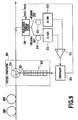
- an optical signal (A in the figure) generated from a transmitter 1 is transmitted to a transmission optical fiber 2 and is transmitted to a receiver 5 while being optically amplified by optical repeaters 3 at certain distances.
- the optical signal immediately after transmission is deteriorated in a waveform thereof by dispersions of the transmission optical fiber 2 and the optical repeaters 3 (B in the figure).
- an error is produced in reading the signal by interference between contiguous optical pulses.
- a dispersion compensation means 4 for compensating the dispersion of the transmission line (transmission optical fiber and optical repeater).
- ⁇ D Z ⁇ S ⁇ L ⁇ T
- ⁇ D(ps/nm) designates a dispersion change amount
- Z(nm/deg) designates a temperature constant of zero dispersion wavelength shift
- S(ps/nm 2 /km) designates a dispersion slope (wavelength differential of dispersion)
- L(km) designates an optical fiber length.
- a reverse dispersion fiber which has been developed recently (K.Mukasa et. al., "Novel network fiber to manage dispersion at 1.55 ⁇ m with combination of 1.3 ⁇ m zero dispersion single mode fiber", ECOC'97, 1, p. 127 (1997)) is a fiber in which a dispersion/a dispersion slope are provided with signs reverse to the sign of the 1.3 ⁇ m zero dispersion optical fiber (single mode fiber: SMF) and absolute values thereof are near to those of SMF.
- SMF single mode fiber
- the temperature dependency of the dispersion slope has not been investigated.
- a fiber having negative dispersion/dispersion slope as in RDF is provided with temperature dependency of the dispersion slope, that is, the wavelength dependency of the temperature dependency of the dispersion which cannot be disregarded.
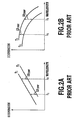
- Fig. 2A and Fig. 2B schematically show respective dispersion curves (dispersion vs wavelength) of SMF and RDF.
- dispersion vs wavelength of the fiber having a negative dispersion slope of a dispersion as in RDF
- structural dispersion is adjusted by devising a refractive index profile and dispersion on a side of a long wavelength is increased in a negative direction. Therefore, when dispersion vs wavelength of the fiber is plotted, whereas dispersion vs wavelength of SMF substantially becomes a linear line, that of RDF becomes a line having a radius of curvature.
- This can be expressed also as an absolute value of a quartic dispersion (wavelength differential of dispersion slope) is larger than that of SMF.
- Fig. 3 shows curves produced by measuring temperature dependency constants of dispersions with regard to SMF and RDF and the temperature dependency constants are plotted with respect to four wavelengths.
- An inclination of a liner line produced by connecting the four points becomes equivalent to temperature dependency constants of the dispersion slopes.
- the value for RDF is 1.48 ⁇ 10 -5 ps/km/nm 2 /deg which is larger than the value of SMF by one order of magnitude.
- ⁇ (nm) a wavelength bandwidth of an optical signal in an optical transmission system
- ⁇ T (deg) a temperature variation is defined as ⁇ T (deg)
- ⁇ D(ps/nm) a dispersion change amount difference ⁇ D(ps/nm) is represented by the following equation.
- ⁇ D ⁇ T ⁇ L ⁇ T ⁇
- a dispersion of a value which differs among channels is produced by a temperature change in WDM transmission of high speed/wide bandwidth by the temperature dependency of the dispersion slope provided to the optical fiber. Therefore, even when the variation amount of the dispersion is compensated by the adaptive type dispersion equalizer by the same amount over a total wavelength bandwidth, there poses a problem that the variation amount exceeds the allowable dispersion value depending on channels.
- a method of monitoring a dispersion on a transmission optical fiber in a wavelength division multiplexing optical transmission system comprising the steps of extracting two or more of wavelength channels 1 to n from the transmission optical fiber and monitoring dispersions of the extracted wavelength channels.
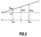
- the step of monitoring the dispersions can include the steps of measuring a first dispersion value in the extracted wavelength channels 1 to n (wavelength: ⁇ mon1 to ⁇ monn ) at a certain temperature T 1 (°C), measuring a second dispersion value in the wavelength channels 1 to n at a certain other temperature T 2 (°C), providing dispersion variation amounts ⁇ D mon1 to ⁇ D monn in the extracted wavelength channels 1 to n from a difference between the measured first dispersion value and the measured second dispersion value, and a step of providing a dispersion variation amount at an arbitrary wavelength ( ⁇ ) based on the provided dispersion variation amounts ⁇ D mon1 to ⁇ D monn.
- the step of providing the dispersion variation amount can calculate a dispersion variation amount ⁇ D( ⁇ ) in an arbitrary wavelength ( ⁇ ) by the following equation.
- ⁇ D( ⁇ ) ⁇ D mon 2 - ⁇ D mon 1 ⁇ mon 2 - ⁇ mon 1 . ( ⁇ - ⁇ mon 1 )+ ⁇ D mon 1
- the step of monitoring the dispersions can include the steps of measuring a first dispersion value in a desired wavelength channel at a certain temperature T 1 (°C), measuring a second dispersion value in the desired wavelength channel at a certain other temperature T 2 (°C), and a step of providing a dispersion variation amount in the desired wavelength channel from a difference between the measured first dispersion and the measured second dispersion value.
- a method of compensating a temperature dependency of a dispersion slope in a wavelength division multiplexing optical transmission system comprising the steps of providing the dispersion variation amount ⁇ D( ⁇ ) by the above-described method and compensating the temperature dependency of the dispersion slope by using the provided dispersion variation amount ⁇ D( ⁇ ).
- the step of compensating the temperature dependency of the dispersion slope can include the steps of dividing a signal light on the transmission optical fiber to one or more wavelength channel groups constituted by at least one wavelength channel, and compensating the dispersion in accordance with each of the divided one or more wavelength channel groups.
- the step of compensating the dispersion can be carried out by using one or more tunable dispersion equalizers with a fiber Bragg grating.
- the step of compensating the dispersion can be carried out by using one or more tunable dispersion equalizers with a filter.
- the step of compensating the temperature dependency of the dispersion slope can summarizingly compensate a wavelength dependency of the temperature dependency of the dispersion in all of bandwidths in a wavelength division multiplexing optical transmission system.
- the step of compensating the temperature dependency of the dispersion slope can be carried out by using one or more tunable dispersion equalizers with a fiber Bragg grating.
- the step of compensating the temperature dependency of the dispersion slope can include the step of providing a temperature change in a dispersion compensating optical fiber installed at an optical node.
- a dispersion monitoring apparatus for monitoring a dispersion on a transmission optical fiber in a wavelength division multiplexing optical transmission system, the dispersion monitoring apparatus comprising extracting means for extracting two or more of wavelength channels from the transmission optical fiber and monitoring means for monitoring dispersions of the extracted wavelength channels.
- a dispersion slope temperature dependency compensating apparatus for compensating a temperature dependency of a dispersion slope in a wavelength division multiplexing optical transmission system
- the dispersion slope temperature dependency compensating apparatus comprising monitoring means for monitoring dispersions of two or more of wavelength channels on a transmission optical fiber, and compensating means for compensating a wavelength dependency of the temperature dependency of the dispersion in an arbitrary wavelength channel by using the monitored dispersions.
- the compensating means can include means for dividing a signal light on the transmission optical fiber into one or more wavelength channel groups constituted by at least one wavelength channel, and means for compensating the dispersion in accordance with each of the divided one or more wavelength channel groups.
- the compensating means can include one or more tunable dispersion equalizers with a fiber Bragg grating.
- the compensating means can include one or more tunable dispersion equalizers with a filter.
- the compensating means can summarizingly compensate the wavelength dependency of the temperature dependency of the dispersion in all of bandwidths in a wavelength division multiplexing optical transmission system.
- the compensating means can include one or more tunable equalizers with a fiber Bragg grating.
- the compensating means can include a dispersion compensating optical fiber installed in an optical node, and means for providing a temperature change to the dispersion compensating optical fiber.
- a wavelength division multiplexing optical transmission system without a deterioration in a transmission characteristic by an influence of a temperature dependency of a dispersion slope can be realized.
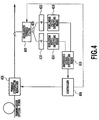
- Fig. 4 shows an apparatus constitution of a dispersion slope temperature dependency compensating apparatus for monitoring and compensating a dispersion variation amount of a transmission optical fiber in a WDM optical transmission system.
- a dispersion detection apparatus described in, for example, Japanese Patent Application No. 2002-164437, U.S. Patent Application Publication No. US2003/0086713 A1, EU Patent Application Publication No. 1309115 and T. Inui, K.R. Tamura, K. Mori and T. Morioka, "Bit rate flexible chirp measurement technique using two-photon absorption", Electronics Letters, vol. 38, no. 23, 7th November 2002.
- the dispersion slope temperature dependency compensating apparatus includes a dispersion detection apparatus and a tunable dispersion equalizer 406.
- the dispersion detection apparatus includes a wavelength tunable filter 408, an optical coupler 409, dispersive media 410 and 412, nonlinear photo-detecting means 414, a difference signal outputting means 416 and a controller 404.
- the wavelength tunable filter 408 is constituted to be able to set a wavelength of light to be picked up.
- the dispersion media 410 and 412 use media having the same absolute value D of a dispersion value and signs different from each other.
- the nonlinear photo-detecting means 414 outputs a voltage in proportion to a square of an intensity of light.
- the difference signal outputting means 416 detects a difference between output voltages of the nonlinear photo-detecting means 414 and outputs a difference signal (voltage difference).
- dispersion variations of two channels are monitored. For example, by controlling the wavelength tunable filter 408 by the controller 404 comprising PC (personal computer) of the dispersion detection apparatus while setting a center wavelength thereof to extract a monitor channel 1( ⁇ mon1 ). a dispersion value in ⁇ mon1 at a certain temperature T 1 (°C) is measured. Light having a wavelength ⁇ mon1 which has passed the wavelength tunable filter 408 is branched at the optical coupler 409 and inputted to the dispersion media 410 and 412.
- the difference signal outputting means 416 calculates a dispersion value from a difference between outputs of the two nonlinear photo-detecting means 414 and stores the dispersion value to the controller 404.
- the center wavelength of the wavelength tunable filter 408 is set to extract a monitor channel 2 ( ⁇ mon2 ) .
- a dispersion value in ⁇ mon2 at T 1 (°C) is measured and the dispersion value is stored to the controller 404.
- the dispersion detection apparatus measures a dispersion value in ⁇ mon1 when there is a change in environment (temperature change) to change from the temperature T 1 (°C) to a certain temperature T 2 (°C), and outputs the dispersion value to the controller 404.
- the controller 404 calculates a difference between the dispersion value in ⁇ mon1 at temperature T 1 (°C) and the dispersion value in ⁇ mon1 at T 2 (°C) to provide a dispersion variation amount ⁇ D mon1 .
- a dispersion variation amount ⁇ D mon2 in ⁇ mon2 is derived from a difference between the dispersion value at temperature T 2 (°C) and the dispersion value at temperature T 1 (°C).
- ⁇ D ( ⁇ ) ⁇ D mon 2 - ⁇ D mon 1 ⁇ mon 2 - ⁇ mon 1 ⁇ ( ⁇ - ⁇ mon 1 ) + ⁇ D mon 1
- adaptive dispersion equalization is carried out by controlling the tunable dispersion equalizer 406 by the controller 404 to provide an appropriate dispersion compensation amount in WDM channel.
- Fig. 6 shows a first embodiment of the invention.
- a transmission line in which a transmission optical fiber of a wavelength division multiplexing optical transmission system having a transmission rate of 40 Gbit/s is constituted by SMF and RDF, there is constructed a constitution of using a dispersion detection apparatus described as a dispersion variation amount monitoring method in T. Inui, K.R. Tamura, K. Mori and T. Morioka, "Bit rate flexible chirp measurement technique using two-photon absorption", Electronics Letters, vol. 38, no. 23, 7th November 2002 .
- SMF 610 having a dispersion value of 40ps/nm and a dispersion compensating fiber (DCF) 612 having a dispersion value of -40ps/nm are used, and as nonlinear photo-detecting means, a silicon avalanche photodiode (Si-APD) 614 showing two-photon absorption at 1.5 ⁇ m band is used.
- the optical fiber is of a dispersion flattened type.
- a cut-off frequency of Si-APD614 sufficiently smaller than the transmission rate is used. Thereby, direct current voltage can be provided as an output.
- an Si-APD having a cut-off frequency of 10MHz is used relative to the transmission rate of 40Gbit/s.
- fiber Bragg gratings can be utilized as dispersion media and SHG (second harmonic generation) crystals can be utilized as non linear photo-detecting means.
- a differential amplifier 616 detects a difference between output voltages of Si-APDs 614 of the two paths and outputs a difference signal (voltage difference).
- the difference signal shows a value in accordance with a magnitude of the dispersion (chirp) and therefore, the difference signal can detects and measures the dispersion of the transmission optical fiber.
- a wavelength tunable filter 608 is installed before a branch to the two paths in the dispersion detection apparatus, the filter is controlled by a controller 604 comprising PC (personal computer) and a center wavelength thereof is set to extract a monitor channel 1 ( ⁇ mon1 ). Further, a dispersion value in ⁇ mon1 at a certain temperature T 1 (°C) is measured and the dispersion value is stored to the controller 604. Similarly, the center wavelength of the wavelength tunable filter is set to extract a monitor channel 2( ⁇ mon2 ), a dispersion value in ⁇ mon2 at T 1 (°C) is measured and the dispersion value is stored to the controller 604.
- a dispersion value in ⁇ mon1 when there is a change in temperature to constitute a certain temperature T 2 (°C ) is measured and a dispersion variation amount ⁇ D mon1 in ⁇ mon1 is derived from a difference from a dispersion value at temperature T 1 (°C).
- measurement of a dispersion value at T 2 (°C) in ⁇ mon2 is carried out.
- a dispersion variation amount ⁇ D mon2 in ⁇ mon2 is derived from a difference between the dispersion value at temperature T 2 (°C) and the dispersion value at temperature T 1 (°C).
- a dispersion variation amount ⁇ D( ⁇ ) in a certain arbitrary wavelength ( ⁇ ) is represented as follows and therefore, the dispersion variation amounts, that is, dispersion amounts to be compensated in respective wavelength channels are known from the equation.
- ⁇ D ( ⁇ ) ⁇ D mon 2 - ⁇ D mon 1 ⁇ mon 2 - ⁇ mon 1 ⁇ ( ⁇ - ⁇ mon 1 )+ ⁇ D mon 1
- a transmission line in which a transmission optical fiber of a wavelength division multiplexing optical transmission system is constituted by SMF and RDF, there is constructed a constitution of using a dispersion detection apparatus described as a dispersion variation amount monitoring method in T. Inui , K . R . Tamura , K. Mori and T. Morioka, "Bit rate flexible chirp measurement technique using two-photon absorption", Electronic Letters, vol . 38, no. 23 , 7th, November 2002 , similar to the first embodiment shown in Fig. 6.
- Center wavelengths of a wavelength tunable filter are set one by one for all of wavelength channels by the controller 604 comprising PC (personal computer) and dispersion values are monitored.
- PC personal computer
- dispersion values in wavelength channels 1 to 32 ( ⁇ mon1 to ⁇ mon32 ) at a certain temperature T 1 ( °C ) are measured and the dispersion values are stored to the controller 604.
- dispersion variation amounts ⁇ D mon1 to ⁇ D mon32 in all of the wavelength channels ⁇ mon1 to ⁇ mon32 can be monitored by differences from the dispersion values at temperature T 1 ( °C ) for the respective wavelength channels.
- T 2 temperature
- a transmission line in which a transmission optical fiber of a wavelength division multiplexing optical transmission system is constituted by SMF and RDF, there is constructed a constitution of using a dispersion detecting apparatus described as a dispersion variation amount monitoring method in T. Inui , K.R. Tamura, K. Mori and T. Morioka, "Bit rate flexible chirp measurement technique using two-photon absorption", Electronics Letters, vol. 38, no. 23, 7th November 2002, similar to the first embodiment shown in Fig. 6.
- Center wavelengths of a wavelength tunable filter are set one by one for a plurality of wavelength channels by the controller 604 comprising PC (personal computer) and dispersion values are monitored.
- PC personal computer
- dispersion values in monitor channels 1 to 32 ( ⁇ mon1 to ⁇ mon32 ) at certain intervals (at intervals of 4 channels in this case) at a certain temperature T 1 ( °C ) are measured and the dispersion values are stored to the controller 604.
- dispersion variation amounts ⁇ D mon1 to ⁇ D mon32 in wavelength channels of ⁇ mon1 to ⁇ mon32 at intervals of 4 channels are monitored from differences from the dispersion values at temperature T 1 (°C).
- T 2 temperature
- the dispersion variation monitoring method can deal with also a case in which the dispersion slope temperature dependency of the transmission optical fiber cannot be approximated by a linear line.
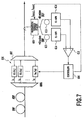
- Fig. 7 shows a fourth embodiment of the invention.
- a transmission optical fiber is constituted by SMF and RDF
- a dispersion detection apparatus described as a dispersion variation amount monitoring method in T. Inui , K.R. Tamura, K. Mori and T. Morioka, "Bit rate flexible chirp measurement technique using two-photon absorption", Electronics Letters, vol. 38, no. 23, 7th November 2002.
- SMF 610 having a dispersion value of 40ps/nm and a dispersion compensating fiber (DCF) 612 having a dispersion value of -40ps/nm are used and as nonlinear photo-detecting means, a silicon avalanche photodiode (Si-APD) 614 showing two-photon absorption at 1. 5 ⁇ m band is used.
- the optical fiber is of a dispersion flattened type.
- a cut-off frequency of Si-APD 614 sufficiently smaller than a transmission rate is used. Thereby, direct current voltage can be provided as an output.
- Si-APD having a cut-off frequency of 10MHz is used relative to a transmission rate of 40Gbit/s.
- the differential amplifier 616 outputs a difference signal (voltage difference) by detecting a difference between output voltages of Si-APDs 614 of the two paths.
- the difference signal shows a value in accordance with a magnitude of dispersion (chirp) and therefore, a dispersion of the transmission optical fiber can be detected and measured.
- Dispersion compensation can be carried out by controlling the tunable dispersion equalizer 606 in the controller 604 comprising PC (personal computer) by using the difference signal.
- the wavelength tunable filter 608 is installed before a branch to the two paths in the dispersion detection apparatus and a center wavelength thereof is set to extract a monitor channel 1( ⁇ mon1 ) by controlling a filter by the controller 604. Further, a dispersion value in ⁇ mon1 at a certain temperature T 1 (°C) is measured and a dispersion value is stored to the controller 604. Similarly, the center wavelength of the wavelength tunable filter is set to extract a monitor channel 2( ⁇ mon2 ), a dispersion value in ⁇ mon2 at T 1 (°C) is measured and the dispersion value is stored to the controller 604.
- a dispersion value in ⁇ mon1 is measured and a dispersion variation amount ⁇ D mon1 in ⁇ mon1 is derived from a difference from the dispersion value at temperature T 1 (°C).
- measurement of a dispersion value at T 2 (°C) in ⁇ mon2 is carried out .
- a dispersion variation amount ⁇ D mon2 in ⁇ mon2 is derived from a difference between the dispersion value at temperature T 2 (°C) and the dispersion value at temperature T 1 (°C).
- a dispersion variation amount ⁇ D( ⁇ ) in a certain arbitrary wavelength ( ⁇ ) is represented as follows and therefore, dispersion variation amounts, that is, dispersion amounts to be compensated in respective wavelength channels are known from the equation.
- ⁇ D ( ⁇ ) ⁇ D mon 2 - ⁇ D mon 1 ⁇ mon 2 - ⁇ mon 1 ⁇ ( ⁇ - ⁇ mon 1 )+ ⁇ D mon 1
- An optical signal transmitted through the transmission optical fiber is branched to respective wavelength channels by an arrayed waveguide grating (AWG) 607 and inputted to the tunable dispersion equalizer 606. Further, dispersion variation amounts in accordance with respective channels derived from the above-described calculation are compensated by controlling a tunable dispersion equalizer 606 by the controller 604.
- the tunable dispersion equalizer 606 in which a dispersion of a chirped fiber Bragg grating is made variable by using a heater can be used. When this is illustrated, as shown by Fig. 8, by compensating a dispersion produced by a temperature change by the tunable dispersion equalizer 606 for respective channels, temperature dependency of the dispersion slope can be compensated.
- the optical signal transmitted to the transmission optical fiber may be divided into one or more wavelength channel groups constituted by a plurality of wavelength channels by an arrayed waveguide grating (AWG).
- ABG arrayed waveguide grating
- the optical signal transmitted through the transmission optical fiber is divided into the one or more wavelength channel.
- variable dispersion equalizer of a planar lightwave circuit (PLC) type which is a variable dispersion equalizer of a filter type described in (K.Takiguchi et al., "Dispersion slope equalizer for dispersion shifted fiber using a lattice-form programmable optical filter on a planar lightwave circuit," J. Lightwave Technol., vol. 16, no. 9, p. 1647 (1998)) may be used.
- LOTADE in place of the chirped fiber Bragg grating, LOTADE (M. Jablonski et al. , "Adjustable coupled two-cavity allpass filter for dispersion slope compensation of optical fibres," Electron Lett., vol. 36, no. 6, p. 511 (2000)) which is a tunable dispersion equalizer of a filter type may be used.
- Fig. 9 shows an eighth embodiment of the invention.
- a constitution of summarizingly compensating dispersions generated by a temperature change for all bandwidths there is constructed a constitution of summarizingly compensating dispersions generated by a temperature change for all bandwidths.
- a tunable dispersion equalizer by a chirped fiber Bragg grating having a wide bandwidth is used.
- a tunable dispersion equalizer 806 of a dispersion slope temperature dependency compensating apparatus introduces an optical signal on the transmission optical fiber to a chirped fiber Bragg grating 803 by an optical circulator 804 and outputs the optical signal again to the transmission optical fiber.
- a number of heaters 802 are attached in a longitudinal direction of the chirped fiber Bragg grating 803. Further, by attaching a temperature gradient in the longitudinal direction, a dispersion variation amount generated by a temperature change on the transmission optical fiber is cancelled by a dispersion variation amount having a reverse characteristic. The temperature dependency of the dispersion slope can be compensated by the method.
- a piezoelectric element in place of the heater of the eighth embodiment, a piezoelectric element can be used.
- the chirped fiber Bragg grating 803 having a wide bandwidth is attached with piezoelectric elements 1102 divided in the longitudinal direction. Further, a dispersion generated by a temperature change is canceled by a dispersion variation amount having a reverse characteristic by changing an elongation and contraction amount of the piezoelectric element in the longitudinal direction. The temperature dependency of the dispersion slope can be compensated by the method.
- Fig. 13 shows an optical fiber accommodation apparatus of the invention.
- the principle of the embodiment is that by finely controlling temperature of a periphery of a dispersion compensating fiber disposed in an optical node, a sum of influences of temperature dependencies of dispersion slopes of a transmission optical fiber and the dispersion compensating fiber in the optical node is restrained.
- An optical fiber accommodation apparatus 1202 of the invention includes a temperature control circuit 1204 and contains a dispersion compensating fiber 1208 in an optical node.
- the transmission optical fiber is provided with a length of L 1 (km) and a dispersion slope temperature constant of ⁇ T1 (ps/nm 2 /km/deg) and the dispersion compensating fiber in the optical fiber accommodation apparatus is provided with a length of L 2 (km) and a dispersion slope temperature constant of ⁇ T2 (ps/nm 2 /km/deg).
- a wavelength bandwidth of an optical system in an optical transmission system is ⁇ (nm) and a range of an allowable dispersion in the transmission system is equal to or larger than - ⁇ D 0 (ps/mn, however, ⁇ D 0 >0) and equal to or smaller than ⁇ D 0 and a temperature change throughout a year to which the transmission optical fiber is subjected is ⁇ T 1 (deg)
- a temperature change ⁇ T 2 (deg) to which the dispersion compensating fiber 1208 is subjected is set to satisfy the following equation by using the temperature control circuit 1204.
- a method of monitoring a dispersion variation amount in two or more of wavelength channels is provided. Further, a method of compensating a wavelength dependency of a temperature dependency of the dispersion by providing an appropriate dispersion individually to the channels or summarizingly for all of bandwidths based on the monitored dispersion variation amounts is provided. According to the present invention, in the WDM optical transmission system, a deterioration in a transmission characteristic by influence of a temperature variation of the dispersion slope can be reduced.
Landscapes
- Physics & Mathematics (AREA)
- Electromagnetism (AREA)
- Engineering & Computer Science (AREA)
- Computer Networks & Wireless Communication (AREA)
- Signal Processing (AREA)
- Optical Communication System (AREA)
Applications Claiming Priority (2)
| Application Number | Priority Date | Filing Date | Title |
|---|---|---|---|
| JP2002214575 | 2002-07-23 | ||
| JP2002214575 | 2002-07-23 |
Publications (3)
| Publication Number | Publication Date |
|---|---|
| EP1385281A2 true EP1385281A2 (de) | 2004-01-28 |
| EP1385281A3 EP1385281A3 (de) | 2006-11-08 |
| EP1385281B1 EP1385281B1 (de) | 2009-12-16 |
Family
ID=29997234
Family Applications (1)
| Application Number | Title | Priority Date | Filing Date |
|---|---|---|---|
| EP03016704A Expired - Lifetime EP1385281B1 (de) | 2002-07-23 | 2003-07-22 | Verfahren und Vorrichtung zur Dispersionsüberwachung, und Verfahren und Vorrichtung zur Kompensation der Temperaturabhängigkeit des Dispersionsgradients |
Country Status (4)
| Country | Link |
|---|---|
| US (1) | US7668459B2 (de) |
| EP (1) | EP1385281B1 (de) |
| CN (1) | CN1305244C (de) |
| DE (1) | DE60330531D1 (de) |
Cited By (4)
| Publication number | Priority date | Publication date | Assignee | Title |
|---|---|---|---|---|
| EP1628150A1 (de) * | 2004-08-19 | 2006-02-22 | Lucent Technologies Inc. | Dispersionskompensator mit Wellenlängennachführung |
| GB2429353B (en) * | 2004-02-23 | 2008-09-10 | Intellambda Systems Inc | A method and apparatus for optical performance monitoring |
| EP1971052A4 (de) * | 2005-12-20 | 2010-02-17 | Zte Corp | Vorrichtung und verfahren zur selbstanpassenden dispersionskompensation |
| EP2007042A4 (de) * | 2006-03-10 | 2012-03-07 | Zte Corp | Wellenlängenmultiplexsystem und restdispersionskompensationseinrichtung und verfahren dafür |
Families Citing this family (13)
| Publication number | Priority date | Publication date | Assignee | Title |
|---|---|---|---|---|
| WO2005071483A1 (en) * | 2004-01-23 | 2005-08-04 | Koheras A/S | Method of generating supercontinuum optical radiation, supercontinuum optical radiation source, and use thereof |
| US20070166033A1 (en) * | 2006-01-10 | 2007-07-19 | Fujitsu Limited | Analyzing the quality of an optical waveform |
| CN101110643B (zh) * | 2006-07-21 | 2011-07-20 | 中兴通讯股份有限公司 | 一种实现波长集中调整控制的系统及方法 |
| JP5282561B2 (ja) * | 2008-12-22 | 2013-09-04 | 富士通株式会社 | 伝送装置および分散値設定方法 |
| JP4894888B2 (ja) * | 2009-05-29 | 2012-03-14 | 富士通株式会社 | 分散補償装置、分散補償方法、光受信装置および光受信方法 |
| US8606119B2 (en) * | 2010-08-27 | 2013-12-10 | Finisar Corporation | Optical channel monitor |
| CN102299745B (zh) * | 2011-07-08 | 2014-03-19 | 中国联合网络通信集团有限公司 | 色散调节方法及装置 |
| US9294194B2 (en) * | 2013-08-19 | 2016-03-22 | Virtual Instruments Corporation | Network monitoring using thin film splitters and avalanche photodiode detectors in multimode application |
| US10788633B2 (en) * | 2018-04-30 | 2020-09-29 | Hewlett Packard Enterprise Development Lp | Complementary reverse order filters |
| US11290184B2 (en) | 2019-03-01 | 2022-03-29 | Molex, Llc | Switchable dispersion compensating module |
| CN113014323B (zh) | 2019-12-20 | 2024-02-09 | 光联通讯技术有限公司美国分部 | 光传送装置及光通信系统 |
| TWI722727B (zh) * | 2019-12-20 | 2021-03-21 | 美商光聯通訊技術有限公司美國分部 | 光傳送裝置及光通訊系統 |
| JP7729374B2 (ja) * | 2021-03-03 | 2025-08-26 | 日本電気株式会社 | 光制御装置、中継器、及び光制御装置の制御方法 |
Citations (2)
| Publication number | Priority date | Publication date | Assignee | Title |
|---|---|---|---|---|
| US20010048798A1 (en) | 2000-01-31 | 2001-12-06 | Eisuke Sasaoka | Choromatic dispersion compensating module and optical transmission system using the same |
| US20020015207A1 (en) | 2000-08-07 | 2002-02-07 | Hiroki Ooi | Method and system for compensating chromatic dispersion |
Family Cites Families (14)
| Publication number | Priority date | Publication date | Assignee | Title |
|---|---|---|---|---|
| JP3341979B2 (ja) | 1997-05-19 | 2002-11-05 | 日本電信電話株式会社 | 分散スロープ補償器 |
| US6307988B1 (en) * | 1999-02-18 | 2001-10-23 | Lucent Technologies Inc. | Optical fiber communication system incorporating automatic dispersion compensation modules to compensate for temperature induced variations |
| JP2001189696A (ja) | 1999-10-19 | 2001-07-10 | Nippon Telegr & Teleph Corp <Ntt> | 分散スロープ補償器 |
| AU2000275586A1 (en) | 2000-01-31 | 2001-08-14 | Sumitomo Electric Industries, Ltd. | Wavelength dispersion compensation module and optical transmission system including the same |
| JP3910003B2 (ja) | 2000-05-29 | 2007-04-25 | 富士通株式会社 | 光受信局、光通信システム及び分散制御方法 |
| US6396982B1 (en) * | 2000-08-01 | 2002-05-28 | Rich Key Technologies Limited | Bimetal-based temperature stabilized multi-FBG package with tunable mechanism |
| JP3672484B2 (ja) | 2000-08-23 | 2005-07-20 | 日本電信電話株式会社 | 群遅延分散エミュレータ |
| JP2002077053A (ja) | 2000-09-05 | 2002-03-15 | Fujitsu Ltd | 波長分散補償方式 |
| US6980738B1 (en) * | 2001-01-26 | 2005-12-27 | Ciena Corporation | Method and system for providing tunable dispersion compensation |
| JP3798640B2 (ja) * | 2001-03-02 | 2006-07-19 | 富士通株式会社 | 受信装置及び受信信号の波形劣化補償方法並びに波形劣化検出装置及び方法並びに波形測定装置及び方法 |
| US6879755B2 (en) * | 2001-07-25 | 2005-04-12 | Teraxion Inc. | Optical structure for the compensation of chromatic dispersion and dispersion slope in a light signal |
| JP3771830B2 (ja) | 2001-10-26 | 2006-04-26 | 日本電信電話株式会社 | 自動分散補償回路付き光波長多重伝送システム |
| JP2003204303A (ja) * | 2001-11-02 | 2003-07-18 | Nippon Telegr & Teleph Corp <Ntt> | 分散検知装置および分散検知方法 |
| JP4642458B2 (ja) * | 2004-12-28 | 2011-03-02 | 富士通株式会社 | 波長分散発生装置 |
-
2003
- 2003-07-21 US US10/624,082 patent/US7668459B2/en not_active Expired - Fee Related
- 2003-07-22 EP EP03016704A patent/EP1385281B1/de not_active Expired - Lifetime
- 2003-07-22 DE DE60330531T patent/DE60330531D1/de not_active Expired - Lifetime
- 2003-07-23 CN CNB031461220A patent/CN1305244C/zh not_active Expired - Fee Related
Patent Citations (2)
| Publication number | Priority date | Publication date | Assignee | Title |
|---|---|---|---|---|
| US20010048798A1 (en) | 2000-01-31 | 2001-12-06 | Eisuke Sasaoka | Choromatic dispersion compensating module and optical transmission system using the same |
| US20020015207A1 (en) | 2000-08-07 | 2002-02-07 | Hiroki Ooi | Method and system for compensating chromatic dispersion |
Cited By (7)
| Publication number | Priority date | Publication date | Assignee | Title |
|---|---|---|---|---|
| GB2429353B (en) * | 2004-02-23 | 2008-09-10 | Intellambda Systems Inc | A method and apparatus for optical performance monitoring |
| US7885541B2 (en) | 2004-02-23 | 2011-02-08 | Dynamic Method Enterprises Limited | Method and apparatus for optical performance monitoring |
| EP1628150A1 (de) * | 2004-08-19 | 2006-02-22 | Lucent Technologies Inc. | Dispersionskompensator mit Wellenlängennachführung |
| EP1971052A4 (de) * | 2005-12-20 | 2010-02-17 | Zte Corp | Vorrichtung und verfahren zur selbstanpassenden dispersionskompensation |
| AU2005339457B2 (en) * | 2005-12-20 | 2010-07-22 | Zte Corporation | An apparatus and method for self-adaptive dispersion compensating |
| EP2007042A4 (de) * | 2006-03-10 | 2012-03-07 | Zte Corp | Wellenlängenmultiplexsystem und restdispersionskompensationseinrichtung und verfahren dafür |
| US8886050B2 (en) | 2006-03-10 | 2014-11-11 | Zte Corporation | Wavelength division multiplexing system, method and device for its residual dispersion compensation |
Also Published As
| Publication number | Publication date |
|---|---|
| DE60330531D1 (de) | 2010-01-28 |
| EP1385281B1 (de) | 2009-12-16 |
| US20070242956A1 (en) | 2007-10-18 |
| US7668459B2 (en) | 2010-02-23 |
| CN1305244C (zh) | 2007-03-14 |
| CN1479478A (zh) | 2004-03-03 |
| EP1385281A3 (de) | 2006-11-08 |
Similar Documents
| Publication | Publication Date | Title |
|---|---|---|
| US7668459B2 (en) | Dispersion monitoring method and apparatus and dispersion slope temperature dependency compensation method and apparatus | |
| US7489880B2 (en) | Apparatus and method for measuring the dispersion of a fiber span | |
| US6594428B1 (en) | Dispersion compensating optical transmission line and system | |
| EP0626768B1 (de) | Lichtwellenleiternetzwerk mit hoher Kapazität und Lichtwellenleiter | |
| US7653310B2 (en) | Wavelength division multiplex (WDM) transmission system | |
| US7433599B2 (en) | Automatic dispersion compensation device and compensation method | |
| US20020015207A1 (en) | Method and system for compensating chromatic dispersion | |
| US20080212962A1 (en) | Chirp measurement method, chirp measurement apparatus and their application | |
| WO2023065010A1 (en) | Dispersion compensating discrete phase filters | |
| US20010048539A1 (en) | Optical transmission system | |
| Walter et al. | Chromatic dispersion variations in ultra-long-haul transmission systems arising from seasonal soil temperature variations | |
| US7519295B2 (en) | Apparatus and method for commissioning an optical transmission system | |
| EP1257076A1 (de) | Modul zur kompensation von wellenlängendispersion und optisches übertragungssystem mit demselben | |
| Eggleton | Dynamic dispersion compensation devices for high speed transmission systems | |
| US20060067700A1 (en) | Wavelength division multiplexing optical transmission system and wavelength division multiplexing optical transmission method | |
| US6980738B1 (en) | Method and system for providing tunable dispersion compensation | |
| CN102484532A (zh) | 通信系统、色散斜率赋予器以及通信方法 | |
| JP3147563B2 (ja) | 光分散補償方法および光分散補償器 | |
| JP2004072759A (ja) | 分散モニタ方法及びその装置、並びに分散スロープ温度依存性補償方法及びその装置 | |
| Westbrook et al. | Measurement of pulse degradation using all-optical 2R regenerator | |
| US7881610B2 (en) | Method of transmitting an optical signal in an optical transmission system and optical transmission system for implementing such a method | |
| Sano et al. | Adaptive Dispersion Equalization by Monitoring Relative Phase Shift Between Spacing-FixedWDM Signals | |
| JP3974471B2 (ja) | 光伝送システム | |
| Ghosh | Design and comparative performance analysis of wideband CFBG with multi narrowband gratings for DWDM system | |
| EP1294114A1 (de) | Wdm-überwachungssystem |
Legal Events
| Date | Code | Title | Description |
|---|---|---|---|
| PUAI | Public reference made under article 153(3) epc to a published international application that has entered the european phase |
Free format text: ORIGINAL CODE: 0009012 |
|
| 17P | Request for examination filed |
Effective date: 20030722 |
|
| AK | Designated contracting states |
Kind code of ref document: A2 Designated state(s): AT BE BG CH CY CZ DE DK EE ES FI FR GB GR HU IE IT LI LU MC NL PT RO SE SI SK TR |
|
| AX | Request for extension of the european patent |
Extension state: AL LT LV MK |
|
| PUAL | Search report despatched |
Free format text: ORIGINAL CODE: 0009013 |
|
| AK | Designated contracting states |
Kind code of ref document: A3 Designated state(s): AT BE BG CH CY CZ DE DK EE ES FI FR GB GR HU IE IT LI LU MC NL PT RO SE SI SK TR |
|
| AX | Request for extension of the european patent |
Extension state: AL LT LV MK |
|
| AKX | Designation fees paid |
Designated state(s): DE FR GB |
|
| 17Q | First examination report despatched |
Effective date: 20071022 |
|
| GRAP | Despatch of communication of intention to grant a patent |
Free format text: ORIGINAL CODE: EPIDOSNIGR1 |
|
| GRAS | Grant fee paid |
Free format text: ORIGINAL CODE: EPIDOSNIGR3 |
|
| GRAA | (expected) grant |
Free format text: ORIGINAL CODE: 0009210 |
|
| AK | Designated contracting states |
Kind code of ref document: B1 Designated state(s): DE FR GB |
|
| REG | Reference to a national code |
Ref country code: GB Ref legal event code: FG4D |
|
| REF | Corresponds to: |
Ref document number: 60330531 Country of ref document: DE Date of ref document: 20100128 Kind code of ref document: P |
|
| PLBE | No opposition filed within time limit |
Free format text: ORIGINAL CODE: 0009261 |
|
| STAA | Information on the status of an ep patent application or granted ep patent |
Free format text: STATUS: NO OPPOSITION FILED WITHIN TIME LIMIT |
|
| 26N | No opposition filed |
Effective date: 20100917 |
|
| REG | Reference to a national code |
Ref country code: FR Ref legal event code: PLFP Year of fee payment: 13 |
|
| PGFP | Annual fee paid to national office [announced via postgrant information from national office to epo] |
Ref country code: DE Payment date: 20150730 Year of fee payment: 13 Ref country code: GB Payment date: 20150724 Year of fee payment: 13 |
|
| PGFP | Annual fee paid to national office [announced via postgrant information from national office to epo] |
Ref country code: FR Payment date: 20150730 Year of fee payment: 13 |
|
| REG | Reference to a national code |
Ref country code: DE Ref legal event code: R119 Ref document number: 60330531 Country of ref document: DE |
|
| GBPC | Gb: european patent ceased through non-payment of renewal fee |
Effective date: 20160722 |
|
| PG25 | Lapsed in a contracting state [announced via postgrant information from national office to epo] |
Ref country code: FR Free format text: LAPSE BECAUSE OF NON-PAYMENT OF DUE FEES Effective date: 20160801 Ref country code: DE Free format text: LAPSE BECAUSE OF NON-PAYMENT OF DUE FEES Effective date: 20170201 |
|
| REG | Reference to a national code |
Ref country code: FR Ref legal event code: ST Effective date: 20170331 |
|
| PG25 | Lapsed in a contracting state [announced via postgrant information from national office to epo] |
Ref country code: GB Free format text: LAPSE BECAUSE OF NON-PAYMENT OF DUE FEES Effective date: 20160722 |