EP1385433B1 - Trokar-zugvorrichtung und verfahren - Google Patents
Trokar-zugvorrichtung und verfahren Download PDFInfo
- Publication number
- EP1385433B1 EP1385433B1 EP01939023A EP01939023A EP1385433B1 EP 1385433 B1 EP1385433 B1 EP 1385433B1 EP 01939023 A EP01939023 A EP 01939023A EP 01939023 A EP01939023 A EP 01939023A EP 1385433 B1 EP1385433 B1 EP 1385433B1
- Authority
- EP
- European Patent Office
- Prior art keywords
- shaft
- traction
- instrument according
- obturator
- tip
- Prior art date
- Legal status (The legal status is an assumption and is not a legal conclusion. Google has not performed a legal analysis and makes no representation as to the accuracy of the status listed.)
- Expired - Lifetime
Links
- 238000000034 method Methods 0.000 title description 23
- 239000004744 fabric Substances 0.000 description 74
- 210000003815 abdominal wall Anatomy 0.000 description 60
- 210000001519 tissue Anatomy 0.000 description 45
- 230000008901 benefit Effects 0.000 description 15
- 239000000463 material Substances 0.000 description 14
- 210000000056 organ Anatomy 0.000 description 12
- 230000035515 penetration Effects 0.000 description 11
- 241001631457 Cannula Species 0.000 description 9
- 238000003780 insertion Methods 0.000 description 8
- 230000037431 insertion Effects 0.000 description 8
- 230000007246 mechanism Effects 0.000 description 7
- 210000001835 viscera Anatomy 0.000 description 6
- 230000008569 process Effects 0.000 description 5
- 229920000742 Cotton Polymers 0.000 description 4
- 210000000683 abdominal cavity Anatomy 0.000 description 4
- 238000010276 construction Methods 0.000 description 4
- 230000007812 deficiency Effects 0.000 description 4
- 230000001965 increasing effect Effects 0.000 description 4
- 238000001356 surgical procedure Methods 0.000 description 4
- 210000001015 abdomen Anatomy 0.000 description 3
- 210000003195 fascia Anatomy 0.000 description 3
- 230000035876 healing Effects 0.000 description 3
- 210000003205 muscle Anatomy 0.000 description 3
- 210000004303 peritoneum Anatomy 0.000 description 3
- 238000000926 separation method Methods 0.000 description 3
- CURLTUGMZLYLDI-UHFFFAOYSA-N Carbon dioxide Chemical compound O=C=O CURLTUGMZLYLDI-UHFFFAOYSA-N 0.000 description 2
- 230000009471 action Effects 0.000 description 2
- 230000004075 alteration Effects 0.000 description 2
- 230000000694 effects Effects 0.000 description 2
- 238000002357 laparoscopic surgery Methods 0.000 description 2
- 238000012986 modification Methods 0.000 description 2
- 230000004048 modification Effects 0.000 description 2
- 210000001087 myotubule Anatomy 0.000 description 2
- 239000004033 plastic Substances 0.000 description 2
- 230000000750 progressive effect Effects 0.000 description 2
- 239000007787 solid Substances 0.000 description 2
- 238000006467 substitution reaction Methods 0.000 description 2
- 239000004753 textile Substances 0.000 description 2
- 206010021620 Incisional hernias Diseases 0.000 description 1
- 241000755266 Kathetostoma giganteum Species 0.000 description 1
- 210000003484 anatomy Anatomy 0.000 description 1
- 230000015572 biosynthetic process Effects 0.000 description 1
- 229910002092 carbon dioxide Inorganic materials 0.000 description 1
- 239000001569 carbon dioxide Substances 0.000 description 1
- 239000011248 coating agent Substances 0.000 description 1
- 238000000576 coating method Methods 0.000 description 1
- 230000008602 contraction Effects 0.000 description 1
- 230000001627 detrimental effect Effects 0.000 description 1
- 238000005516 engineering process Methods 0.000 description 1
- 230000002708 enhancing effect Effects 0.000 description 1
- 239000002657 fibrous material Substances 0.000 description 1
- 210000000232 gallbladder Anatomy 0.000 description 1
- 230000002401 inhibitory effect Effects 0.000 description 1
- 238000002955 isolation Methods 0.000 description 1
- 239000002184 metal Substances 0.000 description 1
- 230000003287 optical effect Effects 0.000 description 1
- 238000004064 recycling Methods 0.000 description 1
- 239000012858 resilient material Substances 0.000 description 1
- 229920001169 thermoplastic Polymers 0.000 description 1
- 239000012815 thermoplastic material Substances 0.000 description 1
- 239000004416 thermosoftening plastic Substances 0.000 description 1
- 230000007704 transition Effects 0.000 description 1
- 238000012800 visualization Methods 0.000 description 1
Images






Classifications
-
- A—HUMAN NECESSITIES
- A61—MEDICAL OR VETERINARY SCIENCE; HYGIENE
- A61B—DIAGNOSIS; SURGERY; IDENTIFICATION
- A61B17/00—Surgical instruments, devices or methods
- A61B17/34—Trocars; Puncturing needles
-
- A—HUMAN NECESSITIES
- A61—MEDICAL OR VETERINARY SCIENCE; HYGIENE
- A61B—DIAGNOSIS; SURGERY; IDENTIFICATION
- A61B17/00—Surgical instruments, devices or methods
- A61B17/34—Trocars; Puncturing needles
- A61B17/3417—Details of tips or shafts, e.g. grooves, expandable, bendable; Multiple coaxial sliding cannulas, e.g. for dilating
- A61B17/3421—Cannulas
-
- A—HUMAN NECESSITIES
- A61—MEDICAL OR VETERINARY SCIENCE; HYGIENE
- A61B—DIAGNOSIS; SURGERY; IDENTIFICATION
- A61B17/00—Surgical instruments, devices or methods
- A61B17/34—Trocars; Puncturing needles
- A61B17/3476—Powered trocars, e.g. electrosurgical cutting, lasers, powered knives
-
- A—HUMAN NECESSITIES
- A61—MEDICAL OR VETERINARY SCIENCE; HYGIENE
- A61B—DIAGNOSIS; SURGERY; IDENTIFICATION
- A61B17/00—Surgical instruments, devices or methods
- A61B17/34—Trocars; Puncturing needles
- A61B17/3494—Trocars; Puncturing needles with safety means for protection against accidental cutting or pricking, e.g. limiting insertion depth, pressure sensors
- A61B17/3496—Protecting sleeves or inner probes; Retractable tips
-
- A—HUMAN NECESSITIES
- A61—MEDICAL OR VETERINARY SCIENCE; HYGIENE
- A61B—DIAGNOSIS; SURGERY; IDENTIFICATION
- A61B17/00—Surgical instruments, devices or methods
- A61B17/34—Trocars; Puncturing needles
- A61B17/3417—Details of tips or shafts, e.g. grooves, expandable, bendable; Multiple coaxial sliding cannulas, e.g. for dilating
-
- A—HUMAN NECESSITIES
- A61—MEDICAL OR VETERINARY SCIENCE; HYGIENE
- A61B—DIAGNOSIS; SURGERY; IDENTIFICATION
- A61B17/00—Surgical instruments, devices or methods
- A61B17/34—Trocars; Puncturing needles
- A61B17/3417—Details of tips or shafts, e.g. grooves, expandable, bendable; Multiple coaxial sliding cannulas, e.g. for dilating
- A61B17/3421—Cannulas
- A61B17/3431—Cannulas being collapsible, e.g. made of thin flexible material
-
- A—HUMAN NECESSITIES
- A61—MEDICAL OR VETERINARY SCIENCE; HYGIENE
- A61B—DIAGNOSIS; SURGERY; IDENTIFICATION
- A61B17/00—Surgical instruments, devices or methods
- A61B17/32—Surgical cutting instruments
- A61B2017/32006—Surgical cutting instruments with a cutting strip, band or chain, e.g. like a chainsaw
-
- A—HUMAN NECESSITIES
- A61—MEDICAL OR VETERINARY SCIENCE; HYGIENE
- A61B—DIAGNOSIS; SURGERY; IDENTIFICATION
- A61B17/00—Surgical instruments, devices or methods
- A61B17/34—Trocars; Puncturing needles
- A61B17/3417—Details of tips or shafts, e.g. grooves, expandable, bendable; Multiple coaxial sliding cannulas, e.g. for dilating
- A61B2017/3454—Details of tips
-
- A—HUMAN NECESSITIES
- A61—MEDICAL OR VETERINARY SCIENCE; HYGIENE
- A61B—DIAGNOSIS; SURGERY; IDENTIFICATION
- A61B90/00—Instruments, implements or accessories specially adapted for surgery or diagnosis and not covered by any of the groups A61B1/00 - A61B50/00, e.g. for luxation treatment or for protecting wound edges
- A61B90/08—Accessories or related features not otherwise provided for
- A61B2090/0801—Prevention of accidental cutting or pricking
- A61B2090/08021—Prevention of accidental cutting or pricking of the patient or his organs
Definitions
- This invention relates generally to trocar systems and more specifically to obturator apparatus for placing a trocar cannula across a body wall.
- holes can be created through body tissue either by cutting the tissue or by mechanically parting the tissue along lines of weakness. Where tissue is cut, it is severed along a line, which is determined by the direction of the cutting implement. Where tissue is parted, it separates along natural tissue planes such as those defined by muscle fibers or differing layers of tissue such as skin and muscle. Tissue that is mechanically separated tends to heal better than tissue that is cut. With tissue that is mechanically separated the healing process requires only that the affected tissues re-approximate each other. with cut tissue, and in particular muscle fibers, the healing process must reconstruct the damaged tissue, often with resultant scaring and incomplete reconstruction.
- trocar wound sites of 10 millimeters in diameter and higher, made by cutting obturators, require suturing to prevent incisional hernias from occurring. It has also been shown that where the same size would site is created by expanding or parting the wound from a cut of 3 millimeters, for example, that the wound site does not require stitching and tends to heal faster.
- instrument ports in the form of cannulas be placed in the patient's abdominal wall. These cannulas are then used as access ports for the surgeon to place instruments such as scissors and graspers.
- these cannulas have been introduced by using a sharp cutting obturator, placed within the cannula, to cut a line or hole for advancing the cannula through the abdominal wall. The obturator is then removed from the cannula and the cannula is left in place for the duration of the surgery.
- optical trocars have been provided with a clear plastic cutting tip. This allows the surgeon to view the tissue layers as they are cut, and in principle to better control the timing of insertion forces.
- plastic tips are not as sharp as the metal bladed variety and therefore require a higher insertion force which in turn increase abdominal wall distortion. This distortion or tenting brings the obturator tip into closer proximity with the internal organs and increases the chances for potential damage.
- the wound created by such a device is still a cut and not a mechanical separation, as it still suffers from the above-mentioned disadvantages.
- Another manufacturer employs a multistage system whereby a sheath is inserted over a veress needle. The needle is then removed and a conical obturator, placed inside a cannula, is inserted through the sheath thereby expanding it to the desired cannula size. The obturator is then removed leaving the cannula in place.
- This offers the advantage of a smaller initial incision with the veress needle.
- the needle still presents a risk to internal organs, and the system is more expensive and complex than those associated with the cutting obturator devices.
- a cutting element is employed to either create the final size of the wound site or to make a smaller initial wound site that is then expanded to the final size.
- the use of sharp cutting elements common to all systems presents an unavoidable risk to the patient.
- US-A-5 676 670 discloses a surgical instrument according to the preamble of claims 1 and 5, respectively.
- a tubular mesh sleeve is initially disposed in the hollow shaft of the obturator. This sleeve is pulled out of a hole at the tip of the obturator shaft and drawn radially and proximally along the outer surface of the shaft. The mesh sleeve inverts at the distal tip facilitating its movement interiorly of the shaft and its traction with the parted tissue exteriorly of the shaft.
- an apparatus for creating an opening through body tissue.
- the apparatus includes a shaft having an axis and a channel extending axially between a proximal end and a distal end.
- the shaft has a distal tip and a hole in the tip communicating with the channel of the shaft. Portions of the tip define a leading surface of the tip. Means is disposed along this leading surface and is moveable relative to the tip for creating generally opposing forces on the body tissue which tend to part the body tissue and thereby create the opening through the body tissue.
- a surgical instrument is used for creating an opening through an abdominal wall retaining internal organs.
- the instrument includes a shaft having an outer surface and a tip. A sheath initially contacting the body tissue generally at a point extends proximally from the point along the outer surface of the shaft.
- the shaft is operable to create a distal force on the body tissue while the sheath is operable to create a proximal force on the body tissue.
- the proximal force is greater than the distal force in order to create a net proximal force on the abdominal wall tending to separate the abdominal wall from the internal organs as the opening is created.
- a flexible sheath having a tubular configuration extends from an axial channel of the shaft through the distal tip of the shaft.
- a handle is attached to the sheath exteriorly of the shaft and is moveable proximally relative to the shaft to withdraw the sheath from the channel and to progressively invert the sheath at the tip of the shaft.
- the shaft of the surgical instrument has a tubular configuration with an outer surface, an axial channel, and a distal tip. At least one flexible traction tread is carried within the axial channel and extends outwardly of the shaft at the distal tip. A handle attached to the traction tread exteriorly of the shaft is moveable proximally to withdraw the traction tread distally through the distal tip.
- a method for creating an opening in body tissue includes the steps of providing opposing traction treads extending from the axial channel of the shaft outwardly through the hole in the tip of the shaft.
- the body tissue is contacted with the traction treads at the tip of the shaft and the traction treads are moved radially outwardly from the hole in the tip.
- the body tissue is engaged at the tip to produce parting forces on the body tissue tending to separate the body tissue and thereby create the opening through the body tissue.
- first and second cannulas are inserted through body tissue by providing an obturator having a shaft with an outer surface and a traction tread moveable relative to the outer surface. Placing the obturator in the first cannula, the body tissue is engaged with the tread and the tread is moved relative to the outer surface of the shaft to facilitate penetration of the body tissue by the shaft and the first cannula. The obturator is then removed from the first cannula and placed in the second cannula where again the traction thread engages the tissue and facilitates penetration of the body tissue by the shaft in the second cannula. Removing the obturator from the second cannula leaves both the first cannula and the second cannula operatively disposed across the body wall.
- a trocar cannula from a body wall is facilitated by placing a mesh sleeve between the cannula and the body wall.
- the sleeve is provided with properties which exert a radial force on the cannula tending to resist removal of the cannula from the body wall.
- an axial force can be applied to the sleeve to reduce the radial force of the sleeve on the cannula.
- the cannula can be removed from the body wall.
- the obturator In a method for inserting an obturator, the obturator is provided with a shaft having an outer surface and a traction tread moveable along the outer surface of the shaft. The tread is carried within the shaft. As the obturator is moved through the body wall, a first force is applied to the obturator in a first direction and a second force is applied to the obturator in a second generally opposing direction. As the obturator is moved distally relative to the body wall, it engages wall portions which face the outer surface of the shaft and pulls those wall portions proximally along the shaft.
- a trocar system of the present invention is illustrated generally in Figure 1 and designated by the reference numeral 10.
- the system 10 includes a trocar cannula 12 having a seal housing 14, and an obturator 16 with a shaft 18 and handle 21, and including a traction mechanism 23 of particular interest to the present invention.
- the obturator 16 is used in placing the cannula 12 across a body wall such as an abdominal wall 25, associated with a patient 27. In the case of the abdomen, the wall 25 defines an abdominal cavity 29 which includes many organs such as that designated by the reference numeral 30.
- multiple cannulas 32 and 34 are used to provide access across the abdominal wall 25 to facilitate surgical procedures within the abdominal cavity 29.
- the removal of a gallbladder is typically accomplished with such a laparoscopic procedure.
- cannulas 12, 32 and 34 are placed across the abdominal wall 25, each providing a working channel through which various instruments can be inserted and surgically manipulated.
- the cannula 32 is shown with a grasper 36 which can be inserted through the cannula to grasp the organs 30 or other tissue within the abdominal cavity 29.
- a fiber-optic scope 38 is illustrated in Figure 1 operatively disposed through the cannula 34 and across the abdominal wall 25 to provide visualization within the abdominal cavity 29.
- Figures 2-5 are provided and to illustrate the deficiencies of trocars and obturators of the
- FIG. 41 One trocar of the prior art is illustrated in Figure 2 and is designated by the reference numeral 41.
- This trocar includes a cannula 43 and blunt obturator 45.
- an incision 47 is cut entirely through the abdominal wall 25 using a scalpel 50. All of the deficiencies previously discussed with respect to cutting rather than parting the abdominal wall 25 impact this procedure.
- the blunt obturator 45 is moved through the incision to place the cannula 43 across the wall 45. Due to the delicate cutting required by this procedure, placement of this trocar 41 may take as long as 10 minutes. In a procedure requiring the placement of four trocars, this time intensive procedure would require as much as 40 minutes, for example.
- FIG. 3 A self-cutting trocar system 52 of the prior art is illustrated in Figure 3 .
- This system 52 includes a cannula 54 and an obturator 56 having a pair of opposing wings 58. These wings 58 are provided with sharpened outer edges so that they tend to cut a path through the abdominal wall 25. Again, the disadvantage of cutting an incision through the abdominal wall 25 also impacts this embodiment.
- a trocar 61 includes a cannula 63 and obturator 65 having a sharpened point 67.
- a safety shield 70 associated with the obturator 65 is biased to move over the point 67 and to protect the interior organs 30 upon penetration of the abdominal wall 25.
- the trocar 61 is forced through the abdominal wall 25 creating a significant distal force on the wall 25. This distal force provides the wall 25 with a concave shape, commonly referred to as tenting, and tends to bring the point 67 into close proximity to the interior organs 30.
- the point 67 precedes the remainder of the trocar 61 as it cuts the tissue of the wall 25. Therefore, of the deficiencies previously discussed with reference to cutting are applicable to this prior art embodiment. Furthermore, the significant force required for penetration, a force typically as high as ten pounds, coupled with close proximity of the concave wall 25 to the organs 30, tends to provide little time for the safety shield 70 to cover the tip 67. As a consequence, damage to the interior organs 30 has been severe notwithstanding the presence of the safety shield 70.
- the high forces required for penetration are particularly applicable to those trocar systems which require both penetration forces as well as cutting forces.
- this obturator 16 includes the shaft 18, handle 21 and traction mechanism 23.
- the traction mechanism 23 may include a fabric 72 having the configuration of a tube with a first end 74 and a second end 76.
- the word "fabric” refers to any flexible sheet material.
- the shaft 18 can be solid, but in a preferred embodiment it is at least partially hollow to receive the first end 74 of the fabric 72 within the shaft 18.
- the shaft 18 extends to a distal tip 78 having a wall 81 that defines an internal channel 83 and an axial hole 85. This wall 81 is defined by a leading surface 87.
- the tubular fabric 72 is initially disposed with its first end 74 positioned in the interior channel 83.
- the fabric 72 extends distally outwardly through the hole 85 where it inverts and extends proximally along the leading surface 87 and the outer surface 90 of the shaft 18.
- the tubular mesh is preferably attached to a finger engagement means, such as a projection, tab, flange or ring 92.
- the handle 21 of the obturator 16 is placed in the palm of the user's hand and his/her fingers are extended to engage the ring 92.
- the hand of the user is closed drawing the fingers towards the palm of the hand.
- This moves the ring 92 toward the handle 21 and draws the tubular fabric 72 distally through the hole 85 and proximally along the outer surface 90 of the shaft 18.
- the ring 92 moves proximally upwardly in Figure 6
- the first end 74 of the fabric 72 is pulled toward the distal tip 78 where the fabric 72 exits the hole 85 and inverts to move along the outer surface 90.
- the handle 21 can be held stationary with a distally directed force, shown by an arrow 96, while a counter proximal force of equal or greater magnitude is applied to the ring 92, as shown by the arrows 98.
- the tubular fabric 72 discussed with reference to Figure 6 can be any material capable of being pulled along the outer surface 90 of the shaft 18. This material could be organic or inorganic and will generally be elongate so that it can be pulled with some magnitude of force in the axial, proximal direction.
- the tubular fabric 72 of Figure 6 although preferred for that embodiment, could be replaced with just a single traction tread 101 as illustrated in Figure 7 . With this traction tread 101 disposed between the shaft 18 and the abdominal wall 25, the traction tread 101 will engage the tissue of the abdominal wall 25 and pull it proximally relative to the shaft 18 .
- FIG. 11 and 12 Such an embodiment is illustrated in Figures 11 and 12 .
- a single traction tread that is radially continuous, as illustrated in Figures 13-15 may be preferred as it provides complete isolation of the shaft 18 from the abdominal wall 25 ( Figure 1 ).
- the shaft 18 of the obturator 16 is cylindrical and the distal tip 78 is conical or convex as it as illustrated in Figure 13
- this tubular configuration for the traction tread 107 is particularly desirable. With this configuration, the traction tread 107 passes through the axial hole 85 where it inverts and travels radially as shown by arrows 110 in Figure 15 . From this point, the traction tread 107 travels proximally along the surface 90 of the shaft 18, upwardly in Figure 14 .
- the distal tip 78 of the obturator 16 is formed as a pair of planar surfaces 112 and 114 which converts distally in the nature of a flathead screwdriver.
- This configuration lends itself to the opposing pair of tractor treads 101 and 103 previously illustrated in Figures 9 and 10 .
- the traction treads 101 and 103 separate generally at an exit slot 116 best shown in Figure 18 .
- the opposing forces are shown by the arrows 118 and 121 which produce the tissue parting results of particular advantage to the present invention.
- each of these treads 101 and 103 forms a continuous band 123 and 125 respectively.
- the two bands 123, 125 counter rotate through the slot 116, and extend proximally along the surface 90, returning to the interior channel 83 through opposing windows 127 and 130 in the wall 81 of the obturator.
- the abdominal wall 25 is further defined by a fascia 141, muscle tissue 143, and a peritoneum 145.
- the shaft 18 and fabric 72 of the obturator 16 can be inserted through the seal housing 14 and into the cannula 12.
- a distal end 147 of the cannula 12 is disposed through the ring 92 and into the associated tubular fabric 72.
- the trocar system 10 functions by pulling the ring 92 proximally along an outer surface 149 of the cannula 12, upwardly in Figure 22 .
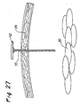
- a cut 152 can be made in the skin or fascia 141. This cut 152 is preferably made to gain access to the muscle tissue 143 which is more easily parted. The cut 152 also marks the desired location for insertion of the trocar system 10. As the ring 92 is drawn upwardly along the cannula 12, the tubular fabric 72 exits the distal hole 85, inverts and follows the ring 92 upwardly along the outer surface 149. At the leading surface 187, the inverting fabric 72 produces opposing radial forces shown by arrows 152 and 154. With these opposing forces, the tissue 143 is parted along the line of weakness 94 ( Figure 6 ) as the trocar system 10 is moved relatively into the abdominal wall 25. It will be noted that the arrows 152 and 154 are merely representative of all of the radial forces which emanate from the hole 85 as shown by the arrows 110 in Figure 15 .
- the ring 92 can be drawn further upwardly along the cannula 12 into contact with the seal housing 14. In a preferred embodiment, this disposition of the ring 92 will cause the first end 74 of the tubular fabric 72 to exit the axial hole 85 of the shaft 18 ( Figure 25 ). At this point, the obturator 16 can be removed, leaving the seal housing 14, associated cannula 12 and tubular fabric 72. With the obturator 16 removed, the interior working channel of the cannula 12 is vacated to facilitate access with surgical instruments, such as the endoscope 38 and grasper 36 illustrated in Figure 1 .
- the trocar system 10 of the present invention offers significant advantages.
- Noteworthy in this embodiment is the fact that the tubular fabric 72 remains between the cannula 12 and the abdominal wall 25 even after the obturator 16 is removed. In this position, the high traction characteristics which facilitated penetration of the abdominal wall 25 by the trocar system 10, remains to ensure that the cannula 12 stays in place during the insertion and removal of surgical instruments.
- the structure that aided in penetration of the abdominal wall 25 now aids in maintaining the cannula 12 in its preferred operative disposition.
- the cannula 12 and associated valve housing 14 can be removed, from the ring 92 and attached tubular fabric 72.
- This removal of the cannula 12 may be inhibited in an embodiment wherein the tubular fabric 72 is automatically biased to a reduced profile. This bias tends to exert radial forces on the cannula increasing the amount of friction which must be overcome to separate the cannula 12 from the tubular fabric 72.
- FIG. 29-32 An additional embodiment of the invention is illustrated in the progressive views of Figures 29-32 , wherein elements of structure similar to those previously discussed are designated with the same reference numeral followed by the lower case letter "a.”
- the trocar system 10a is shown with the cannula 12a and associated seal housing 14a.
- the obturator 16a includes the shaft 18a and handle 21a, as well as the axial hole 85a.
- the tubular fabric is designated with a reference numeral 72a. Note that in this embodiment the tubular fabric 72a also extends through the valve housing 14a to the ring 92a which is disposed proximally of the valve housing 14a.
- This embodiment differs from that previously disclosed in that the obturator 16a and tubular fabric 72a are disposed entirely within the working channel of the cannula 12a.
- the obturator 16a with fabric 72a is inserted into the cannula 12a in the initial step of operation.
- the fabric 72a is exposed to the abdominal wall 25 ( Figure 1 ) only in a distal region 163 where the obturator shaft 19a is exposed distally of the end 132a of the cannula 12a. Since this region produces the parting forces represented by the arrows 152 and 154 in Figure 22 , as well as the proximal counter forces, represented by the arrows 98 in Figure 6 , this embodiment provides many of the advantages previously discussed.
- the obturator 16a with tubular fabric 72a is disposed in the cannula 12a.
- the leading edge 87a is brought into contact with the body wall 25a and the ring 92a is drawn proximally toward the handle 21a as illustrated in Figure 30 .
- the tubular mesh emanates from the axial hole 85a it inverts in the manner previously discussed pulling the abdominal wall 25a upwardly onto the cannula 12a.
- the ring 92a is drawn proximally into an abutting relationship with the handle 21a as illustrated in Figure 31 .
- the cannula 12a should be fully inserted through the abdominal wall 25a.
- the obturator 16a as well as the tubular fabric 72a can be entirely withdrawn leaving the cannula 12a operatively disposed across the abdominal wall 25a as illustrated in Figure 32 .
- the obturator 16a and tubular fabric 72a can be repeatedly used in the placement of multiple cannulas, such as the cannula 12a.
- a first cannula can be placed through the abdominal wall using the obturator 16a.
- the first cannula can be left in place as illustrated in Figure 32 .
- the obturator 16a can be inserted into a second cannula to facilitate its placement across the abdominal wall.
- the same obturator 16a can then be removed to facilitate placement of additional cannulas.
- FIG. 33-35 A further embodiment of the invention is illustrated in Figures 33-35 where elements of structure similar to those previously discussed are designated with the same reference numeral followed by the lower case letter "b.”
- This embodiment is similar to that discussed with reference to Figure 29 in that the obturator 16b and tubular fabric 72b are formed as a subassembly which is inserted into the cannula 12b.
- the tubular fabric 72b is only exposed in the distal region 163b distally of the distal end 132b of the cannula 12b.
- the embodiment of Figure 33 differs from that of Figure 29 in that the tubular fabric 72b moving proximally is not disposed between the obturator shaft 18b and the cannula 12b. Rather, the proximally moving tubular fabric 72a is disposed exteriorly of the shaft 18b only in the distal region 163b. At the proximal end of this region 163b, in proximity to the distal end 132b of the cannula 12b, the proximal moving tubular fabric 72b is directed through the windows 127b and 130b back into the interior channel 83b of the shaft 18b.
- the second end 76b of the tubular fabric 72b is attached to the ring 92b.
- This calls for a special construction of the shaft 18b and ring 92b which is best described with reference to the radial cross section view of Figure 34 .
- the shaft 18b can be formed with axial slots 165 which extend along the shaft 18b beneath the ring 92b. These axial slots 165 are preferably equally spaced around the circumference of the shaft 18b.
- Spokes 167 integrally molded with the ring 92b, can be positioned in the slots 165 of the shaft 18b to extend from regions exterior of the shaft 18b to regions interior of the shaft 18b.
- the second end 76b of the tubular mesh can be attached to the spokes 167.
- FIG. 5 A similar embodiment of the invention is illustrated in Figure 5 where elements of structure similar to those previously discussed are designated by the same reference numerals followed by the lower case letter "c.”
- the obturator shaft 18c is formed at its distal end with a structure similar to that illustrated in Figure 16 .
- the shaft 18c is formed with the converging planar surfaces 112c and 114c and the separate traction treads 101c and 103c, best illustrated in Figure 36 .
- this embodiment requires both of the windows 127c and 133c, as well as the slot 116c.
- This embodiment of the trocar system 10c offers a further advantage that the obturator 16c can be used repeatedly with multiple cannulas 12c.
- a tension spring 170 is fixed at one end to the handle 21c and at the other end to the first end 74c of the tubular fabric 72c.
- the ring 92c is drawn proximally toward the handle 21c along with the second end 76c of the tubular fabric 72c. This causes the first end 74c of the tubular fabric 72c to move distally stretching the spring 170.
- the spring 170 is stretched even further ( Figure 38 ) as the ring 92c is drawn proximally and the traction treads 101c and 103c pass outwardly through the axial slot 116c and inwardly through the windows 127c and 130c, respectively.
- the obturator 16c can be withdrawn and the ring 92c released from its proximal-most position ( Figure 38 ).
- the bias of the spring 170 will pull the first ends 74c of the traction treads 101c, 103c proximally.
- the treads 101c, 103c will pass outwardly through the windows 127c, 130c, respectively, and inwardly through the axial slot 116c. This will enable the spring 170 to return to its normal, non-stretched state with the ring 92c disposed in its distal most position.
- spring 170 could be replaced with any biasing means which mechanically, electrically or elastomericallyo, for example, would bias the first end 74c in the proximal direction.
- the structure forming the tubular fabric 72 as well as the various traction treads 101, 103, 105 and 107, is of particular importance to the present invention.
- This structure is preferably formed as a sheet material and is flexible and elongate with at least one tractive surface. These characteristics will be appreciated particularly in those embodiments involving the traction treads 101 and 103 where the width of the treads remains generally constant. In these cases, the tread is able to maintain its width as it exits the distal slot 116 and enters the windows 127 and 130.
- the structure of the fabric is capable of radially expanding and contracting.
- the mesh is biased to the contracted low-profile state, it will occupy less space within the interior channel 83 and more easily feed through the exit hole 85.
- a bias to the contracted state will also facilitate removal of the fabric 72 as illustrated in Figure 28 .
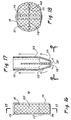
- the fabric 72 preferably has a sheet configuration and can be either woven or non-woven. It can be formed with filaments, which in the preferred embodiment of Figure 39 , are divided into filament groups 170 and 172 that extend in transverse directions. Thus the filaments in the group 170 may extend, in a normal state, perpendicular to the filaments in the group 172, as illustrated in Figure 39 .
- the filament groups 170 and 172 can be woven to form points of intersection 174 where the filaments cross and spaces or interstices 176 between the filaments.
- the fabric 72 will have a thickness equal to the sum of the diameters of a single filament in the group 170 and a single filament in the group 172.
- the filaments in the groups 170 and 172 will provide the fabric 72 with only a single thickness.
- the material 168 will have zero thickness.
- the woven configuration of even this simple embodiment will provide the fabric 72 with three different thicknesses greatly facilitating the traction between the material 168 and the tissue associated with the abdominal wall 25 ( Figure 1 ).
- any one of the filaments in the groups 170 and 172 can be formed from a different material. Solid, non-resilient materials, such as monofilament, will tend to maintain their shape providing more of a mechanical traction to the tissue.
- the filaments could also be formed from fibrous materials, such as cotton, in which case traction would be further enhanced by capillary action.
- the filaments of the groups 170, 172 could also be individually varied in their diameters or thicknesses, or provided with a more tractive surface, shape or coating.
- the filaments forming the group 170 include monofilaments which are alternated with cotton filaments.
- the same alternation of filament materials is applied to the filaments of the group 172.
- significant variations in thickness occur due to the fixed diameter of the monofilaments and the variable diameter of the cotton filaments.
- the resulting material 168 provides many different thicknesses for high mechanical traction and additionally provides the capillary action associated with fibrous cotton material.
- Thermoplastic materials can also be used for the filaments in the groups 170 and 172. These materials will permit the fabric 72 to be biased to a compacted state as illustrated in Figure 40 and stretched to an expanded state as illustrated in Figure 41 .
- This thermoplastic bias facilitates movement of the tubular fabric 72 between a low profile state interiorly of the shaft 18b, and an expanded high profile state exteriorly of the shaft 18b. With a bias to the low profile state, the tubular fabric 72 will automatically contract to achieve the advantages previously discussed.
- the fabric 72 can also be woven in a manner that the filaments of the group 170 are fixed to the filaments of the group 172 at each point of intersection 174. This feature will tend to make the fabric 168 more rigid so that it does not tend to close down on the surface of the cannula 12 or shaft 18 as it is drawn proximally.
- the resulting fabric 72 will also have less of a tendency to expand or contract. This may tend to produce pleats in the fabric 72 particularly where it emanates from the axial hole 85b.
- these pleats 178 can provide the further advantage of texture variations at the critical leading surface 87 of the obturator 16. This additional texture can even further enhance the traction with the tissue where the important parting of the tissue is taking place.
- the filaments forming the group 170 and 172 can remain disconnected at their points of intersection 74. This will enable the filaments to move over each other enhancing their ability to expand and contract.
- the characteristic of this weave is best illustrated in Figure 43 where the fabric 168 tends to maintain its cylindrical configuration as it passes through the axial hole 85 and moves from the low profile state to the high profile state.
- the radial expansion might be desirable as it facilitates the transition of the tubular fabric 72 from the low profile state at the exit hole 85b, to the high profile state exteriorly of the cannula 12 or shaft 18.
- Alternatives for providing different stretch characteristics in different directions are well known in the textile industry and include formation of the fabric 72 with filaments of different material and shape as well as orientation of the filaments relative to the cut of the fabric 168.
- FIG. 44 A further embodiment of the invention is illustrated in Figure 44 where elements of structure similar to those previously discussed are designated with the same reference numeral followed by the lower case letter "d."
- the obturator 16d is illustrated with its wall 81b extending along an axis 181 to form a blunt tip 183 and the exit hole 85d.
- a needle 185 having a sharp conical tip 187 is supported within the interior channel 83d to extend slightly through the axial hole 85d.
- the tubular mesh 82d is disposed around the needle 185 and exits through the axial hole 85d and proximally along the wall 81d in the manner previously discussed.
- the needle 185 can be fixed to the obturator 16b, or can be moveable distally, either manually or automatically, to facilitate penetration of the wall 25.
- the needle 185 can provide a microscopic puncture which precedes the fabric 72d as it exits from the hole 85d.
- This microscopic puncture can provide the initial cut 152 in the fascia 141 and/or facilitate puncture of the peritoneum 145 ( Figure 22 ).
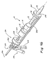
- FIG. 46 An insertion apparatus 201 adapted for use with the trocar system 10 of the present invention is illustrated in Figure 46 .
- This particular embodiment of the trocar system 10 includes the obturator handle 21, valve housing 14, cannula 12 and ring 92 coupled to the tubular fabric 72.
- the insertion apparatus 201 includes a frame 203 fixed to a longitudinal tray 205 that extends along an axis 206 to a distal radial wall 207.
- the frame 203 includes a palm handle 210 and finger handle 212 which operate a ratchet mechanism 214 to move a plunger 216 and a distal engagement pad along the tray 205.
- the trocar system 10 is placed within the tray 205 and aligned axially with its cannula 12 extending through a hole 221 in the distal wall 207.
- the ring 92 is disposed on the proximal side of the wall 207.
- handles 210, 212 moves the plunger 218 axially distally bringing the engagement pad 217 into contact with the handle 21 of the trocar system 10. Further operation of the handles 210 and 212 operates the ratchet assembly 214 to move the cannula 12 distally within the tray 205 of the insertion apparatus 201. With distal movement of the ring 92 inhibited by the wall 207, the ring 92 moves proximally relative to the advancing cannula 12. This deploys the tubular fabric 72 and causes it to move proximally relative to the outer surface of the cannula 12.
- this insertion apparatus 201 can significantly aid in placement of the trocar system 10. It not only provides some mechanical advantage to the process but is also operable by a single hand of the user.
- this embodiment includes the obturator 16b with shaft 18b having the distal tip 78b.
- a pair of gears 230 and 234 are rotatable on the shaft 18b and disposed radially with respect to each other. Teeth 234 and 236 on the circumference of the gears 230 and 232 extend beyond the distal tip 78b and form the leading surface 87b of the obturator 16b.
- the teeth 234 and 236 mesh between the gears 230 and 232 so that these gears turn in opposing directions generating the parting forces illustrated by the arrows 152b and 154b.
- a pilot gear 138 can be used to rotate one of the gears 130, 132 which in turn rotates the opposing gear 232 or 230 respectively.
- the pilot gear 238 can be rotated by any suitable mechanism, such as a belt 241 receiving an applied force from the proximal end of the obturator 16b.
- the traction treads mentioned with respect to previous embodiments take the form of the gear teeth 234 and 236 which are axially continuous and produce the parting forces at the leading surface 187b.
- An end view of this embodiment is illustrated in Figure 48 .
- FIG. 49 A further embodiment of the invention is illustrated in the axial cross section view of Figure 49 and the associated end view of Figure 50 , where elements of structure similar to those previously disclosed are designated by the same reference numeral followed by the lower case letter "E.”
- the obturator 16e includes a single gear 243 exposed at the distal tip 78e.
- the idle gear 238e is rotatable by the belt 241 e alternately clockwise and counter-clockwise. This oscillating movement is transferred to the gear 230e causing its teeth 234e to move back and forth at the leading surface 87e. This oscillating movement is illustrated by an arrow 245 in Figures 49 and 50 .
Landscapes
- Health & Medical Sciences (AREA)
- Surgery (AREA)
- Life Sciences & Earth Sciences (AREA)
- Biomedical Technology (AREA)
- Nuclear Medicine, Radiotherapy & Molecular Imaging (AREA)
- Engineering & Computer Science (AREA)
- Pathology (AREA)
- Heart & Thoracic Surgery (AREA)
- Medical Informatics (AREA)
- Molecular Biology (AREA)
- Animal Behavior & Ethology (AREA)
- General Health & Medical Sciences (AREA)
- Public Health (AREA)
- Veterinary Medicine (AREA)
- Surgical Instruments (AREA)
Claims (21)
- Chirurgisches Instrument mit einem Schaft (18), der eine röhrenartige Gestalt mit einer äußeren Oberfläche, mit einem axialen Kanal und mit einer distalen Spitze (78) aufweist, undmit einer flexiblen Hülle (72), die eine röhrenartige Gestalt aufweist und sich von dem axialen Kanal des Schafts (18) durch die distale Spitze (78) des Schafts (18) nach außen erstreckt,
gekennzeichnet durchein Griffstück (21), das an der Außenseite des Schafts (18) an der Hülle (72) befestigt ist, wobei das Griffstück (21) proximal bewegbar ist, um die Hülle (18) aus dem Kanal zurückzuziehen und um die Hülle (72) nach und nach an der Spitze (78) des Schafts (18) umzudrehen. - Chirurgisches Instrument nach Anspruch 1, dadurch gekennzeichnet,dass der Schaft (18) einen Obturator (16) bildet, der zum Anordnen in einer Kanüle eingerichtet ist, unddass die Hülle (72) so angeordnet ist, dass sie sich proximal aus dem Obturator nach außen erstreckt.
- Chirurgisches Instrument nach Anspruch 2, dadurch gekennzeichnet, dass die Hülle (72) so angeordnet ist, dass sie sich proximal aus dem Obturator und der Kanüle nach außen erstreckt.
- Chirurgisches Instrument nach Anspruch 2, dadurch gekennzeichnet, dass die Hülle so angeordnet ist, dass sie sich proximal zwischen dem Obturator und der Kanüle erstreckt.
- Chirurgisches Instrument mit einem Schaft (18), der eine röhrenartige Gestalt mit einer äußeren Oberfläche, mit einem inneren Kanal und mit einer distalen Spitze (78) aufweist, gekennzeichnet durch wenigstens ein flexibles Reibflächenteil (101), das von dem inneren Kanal des röhrenartigen Schafts (18) mitgeführt ist und das sich an der distalen Spitze (78) aus dem Schaft (18) nach außen erstreckt, und
durch ein Griffstück (21), das an dem Reibflächenteil (101) an der Außenseite des Schafts (18) befestigt ist, wobei das Griffstück (21) proximal bewegbar ist, um das Reibflächenteil (101) distal durch die distale Spitze (78) zurückzuziehen. - Chirurgisches Instrument nach Anspruch 1 oder nach Anspruch 6, dadurch gekennzeichnet, dass die Hülle (72) so eingerichtet ist, dass sie auf den Gewebekörper, mit dem sie in Eingriff gebracht wird, eine größere proximale Kraft als eine distale Kraft ausübt.
- Chirurgisches Instrument nach Anspruch 5, dadurch gekennzeichnet, dass wenigstens zwei Reibflächenteile (101, 103) gleichmäßig beabstandet um den Umfang des Schafts (18) angeordnet sind.
- Chirurgisches Instrument nach Anspruch 7, dadurch gekennzeichnet, dass die beiden Reibflächenteile (101, 103) diametral an dem Schaft (18) angeordnet sind.
- Chirurgisches Instrument nach Anspruch 5, dadurch gekennzeichnet, dass das Reibflächenteil (101) radial durchgehend ist und über eine gewebte Hülle mit einer röhrenartigen Gestalt verfügt.
- Chirurgisches Instrument nach Anspruch 5, dadurch gekennzeichnet, dass das Reibflächenteil (101) axial durchgehend ist und über einen Gurt verfügt.
- Instrument nach Anspruch 5, dadurch gekennzeichnet, dass die Reibflächenteile (101, 103) gewebt sind.
- Instrument nach Anspruch 5, dadurch gekennzeichnet, dass die gewebten Reibflächenteile (101, 103) die Gestalt einer Röhre aufweisen.
- Instrument nach Anspruch 5, dadurch gekennzeichnet, dass die Reibflächenteile (101, 103) distal nach außen durch das Loch des Schafts (18) und proximal der distalen Spitze (78) entlang des Schafts (18) bewegbar sind.
- Instrument nach Anspruch 13, dadurch gekennzeichnet, dass die Reibflächenteile (101, 103) proximal aus dem Schaft (18) nach außen bewegbar sind.
- Instrument nach Anspruch 13, dadurch gekennzeichnet, dass die Reibflächenteile (101, 103) proximal nach innen in dem Schaft (18) bewegbar sind.
- Instrument nach Anspruch 6, dadurch gekennzeichnet, dass die Spitze (78) des Schafts (18) ein Loch aufweist, das mit dem Kanal durch die Spitze verbunden ist, dass das wenigstens eine Reibflächenteil (101) wenigstens über zwei Reibflächenteile (101, 103) verfügt, die sich aus dem Kanal des Schafts (18) nach außen durch das Loch in der Spitze (78) des Schafts (18) erstrecken, um mit dem Körpergewebe an der Spitze (78) des Schafts (18) in Kontakt zu kommen, und dass die Reibflächenteile (101, 103) radial aus dem Loch in der Spitze (78) nach außen bewegbar sind.
- Instrument nach Anspruch 17, dadurch gekennzeichnet, dass die Spitze (78) des Schafts (18) dazu eingerichtet ist, sich zu drehen, um Schwachstellen durch das Körpergewebe zu folgen.
- Instrument nach Anspruch 17, dadurch gekennzeichnet, dass die Reibflächenteile (101, 103) eine Hülse bilden.
- Instrument nach Anspruch 16, dadurch gekennzeichnet,dass die Spitze (78) des Schafts (18) einen Führungsrand und eine äußere Oberfläche aufweist,dass der Führungsrand sich aus dem Loch nach außen erstreckt,dass die äußere Oberfläche sich proximal des Führungsrands erstreckt unddass die Reibflächenteile (101, 103) von einer anfänglichen Lagerstellung in dem Schaft (18) nach außen durch das Loch, radial entlang des Führungsrands und proximal in eine Betriebsstellung entlang der äußeren Oberfläche bewegbar sind.
- Instrument nach Anspruch 19, dadurch gekennzeichnet, dass die Reibflächenteile (101, 103) in der Betriebsstellung in Bezug auf die Reibflächenteile in der Lagerstellung umgedreht sind.
- Instrument nach Anspruch 20, dadurch gekennzeichnet, dass die Reibflächenteile (101, 103) durchgehend sind.
Applications Claiming Priority (1)
| Application Number | Priority Date | Filing Date | Title |
|---|---|---|---|
| PCT/US2001/015390 WO2002091930A1 (en) | 2001-05-11 | 2001-05-11 | Traction trocar apparatus and method |
Publications (2)
| Publication Number | Publication Date |
|---|---|
| EP1385433A1 EP1385433A1 (de) | 2004-02-04 |
| EP1385433B1 true EP1385433B1 (de) | 2008-08-06 |
Family
ID=21742566
Family Applications (1)
| Application Number | Title | Priority Date | Filing Date |
|---|---|---|---|
| EP01939023A Expired - Lifetime EP1385433B1 (de) | 2001-05-11 | 2001-05-11 | Trokar-zugvorrichtung und verfahren |
Country Status (6)
| Country | Link |
|---|---|
| US (2) | US7189249B2 (de) |
| EP (1) | EP1385433B1 (de) |
| JP (1) | JP2004526539A (de) |
| CA (1) | CA2449705A1 (de) |
| DE (1) | DE60135251D1 (de) |
| WO (1) | WO2002091930A1 (de) |
Families Citing this family (36)
| Publication number | Priority date | Publication date | Assignee | Title |
|---|---|---|---|---|
| US7479150B2 (en) * | 2003-09-19 | 2009-01-20 | Tyco Healthcare Group Lp | Trocar insertion apparatus |
| WO2006042114A1 (en) | 2004-10-06 | 2006-04-20 | Cook, Inc. | Emboli capturing device having a coil and method for capturing emboli |
| US8221446B2 (en) | 2005-03-15 | 2012-07-17 | Cook Medical Technologies | Embolic protection device |
| US8945169B2 (en) | 2005-03-15 | 2015-02-03 | Cook Medical Technologies Llc | Embolic protection device |
| US8187298B2 (en) | 2005-08-04 | 2012-05-29 | Cook Medical Technologies Llc | Embolic protection device having inflatable frame |
| JP2007069329A (ja) * | 2005-09-08 | 2007-03-22 | Japan Science & Technology Agency | 微小立体構造操作具の作製方法及びそれによって作製される微小立体構造操作具 |
| US8377092B2 (en) * | 2005-09-16 | 2013-02-19 | Cook Medical Technologies Llc | Embolic protection device |
| US8632562B2 (en) | 2005-10-03 | 2014-01-21 | Cook Medical Technologies Llc | Embolic protection device |
| US8182508B2 (en) | 2005-10-04 | 2012-05-22 | Cook Medical Technologies Llc | Embolic protection device |
| US8252017B2 (en) | 2005-10-18 | 2012-08-28 | Cook Medical Technologies Llc | Invertible filter for embolic protection |
| US8216269B2 (en) * | 2005-11-02 | 2012-07-10 | Cook Medical Technologies Llc | Embolic protection device having reduced profile |
| US8152831B2 (en) | 2005-11-17 | 2012-04-10 | Cook Medical Technologies Llc | Foam embolic protection device |
| US20080071307A1 (en) | 2006-09-19 | 2008-03-20 | Cook Incorporated | Apparatus and methods for in situ embolic protection |
| US20080171984A1 (en) * | 2007-01-11 | 2008-07-17 | Miller Peter C | Cannula driver and system |
| US20080171988A1 (en) * | 2007-01-17 | 2008-07-17 | Erblan Surgical, Inc. | Double-cone sphincter introducer assembly and integrated valve assembly |
| US9901434B2 (en) | 2007-02-27 | 2018-02-27 | Cook Medical Technologies Llc | Embolic protection device including a Z-stent waist band |
| US8100930B2 (en) * | 2007-03-30 | 2012-01-24 | Ethicon Endo-Surgery, Inc. | Tissue moving surgical device |
| US8142356B2 (en) * | 2007-03-30 | 2012-03-27 | Ethicon Endo-Surgery, Inc. | Method of manipulating tissue |
| US8157727B2 (en) * | 2007-07-16 | 2012-04-17 | Ethicon Endo-Surgery, Inc. | Surgical methods and devices with movement assistance |
| US9138307B2 (en) * | 2007-09-14 | 2015-09-22 | Cook Medical Technologies Llc | Expandable device for treatment of a stricture in a body vessel |
| US8419748B2 (en) | 2007-09-14 | 2013-04-16 | Cook Medical Technologies Llc | Helical thrombus removal device |
| US8252018B2 (en) | 2007-09-14 | 2012-08-28 | Cook Medical Technologies Llc | Helical embolic protection device |
| US8795326B2 (en) | 2007-10-05 | 2014-08-05 | Covidien Lp | Expanding seal anchor for single incision surgery |
| US8540744B2 (en) * | 2008-04-01 | 2013-09-24 | Ethicon Endo-Surgery, Inc. | Tissue penetrating surgical device |
| JP5224298B2 (ja) * | 2008-06-19 | 2013-07-03 | 国立大学法人大阪大学 | 管腔壁穿刺用オーバーチューブ |
| US20100194060A1 (en) * | 2008-11-03 | 2010-08-05 | Erblan Surgical, Inc. | Universal closure and method of lubrication |
| US8388644B2 (en) | 2008-12-29 | 2013-03-05 | Cook Medical Technologies Llc | Embolic protection device and method of use |
| US20110237871A1 (en) | 2010-03-25 | 2011-09-29 | Allergan, Inc. | Controller support apparatus |
| US9414816B2 (en) * | 2011-06-23 | 2016-08-16 | Devicor Medical Products, Inc. | Introducer for biopsy device |
| US10646690B2 (en) * | 2012-11-20 | 2020-05-12 | University Of Massachusetts | Flexible surgical sheath and multi-part insertion cannula |
| ITFI20130101A1 (it) * | 2013-05-03 | 2014-11-04 | Fond Istituto Italiano Di Tecnologia | Dispositivo per la penetrazione autonoma e non distruttiva di ambienti |
| US10646250B2 (en) * | 2016-07-19 | 2020-05-12 | Reza Mohajer-Shojaee | Trocar assemblies with movable atraumatic tip and methods for use |
| WO2018183185A1 (en) * | 2017-03-28 | 2018-10-04 | C.R. Bard, Inc. | Implantable prosthetic device |
| CN114010244B (zh) * | 2022-01-06 | 2022-04-12 | 深圳佰特微医疗科技有限公司 | 组织牵引器械 |
| US20240315710A1 (en) * | 2023-03-24 | 2024-09-26 | Mako Surgical Corp. | Anti-Skiving Guide Tube And Surgical System Including The Same |
| CN118216964B (zh) * | 2024-04-23 | 2025-10-31 | 大瓷生物医疗科技(江苏)有限公司 | 一种扩收式腹壁戳孔封闭器及其输送器 |
Family Cites Families (26)
| Publication number | Priority date | Publication date | Assignee | Title |
|---|---|---|---|---|
| US2704071A (en) | 1953-11-23 | 1955-03-15 | Becker Paul | Skin retractor |
| US4243040A (en) * | 1979-09-17 | 1981-01-06 | Beecher William H | Extracting device for removing objects from human body passages |
| US4479497A (en) * | 1982-11-12 | 1984-10-30 | Thomas J. Fogarty | Double lumen dilatation catheter |
| US4469100A (en) * | 1983-03-14 | 1984-09-04 | Hardwick Charles W | Intussuscepting balloon catheter for stone extraction |
| US4606347A (en) * | 1983-03-25 | 1986-08-19 | Thomas J. Fogarty | Inverted balloon catheter having sealed through lumen |
| GB8816033D0 (en) | 1988-07-06 | 1988-08-10 | Ethicon Inc | Improved safety trocar |
| US5350393A (en) | 1992-01-06 | 1994-09-27 | Inbae Yoon | Safety trocar penetrating instrument |
| US5261891A (en) | 1991-01-15 | 1993-11-16 | Ethicon, Inc. | Trocar |
| US5263969A (en) | 1992-04-17 | 1993-11-23 | Phillips Edward H | Tool for the laparoscopic introduction of a mesh prosthesis |
| US5443484A (en) | 1992-06-16 | 1995-08-22 | Loma Linda University Medical Center | Trocar and method for endoscopic surgery |
| US5407427A (en) | 1992-06-16 | 1995-04-18 | Loma Linda University Medical Center | Trocar facilitator for endoscopic surgery |
| US5320611A (en) | 1993-02-04 | 1994-06-14 | Peter M. Bonutti | Expandable cannula having longitudinal wire and method of use |
| US5431676A (en) | 1993-03-05 | 1995-07-11 | Innerdyne Medical, Inc. | Trocar system having expandable port |
| US5643282A (en) * | 1994-08-22 | 1997-07-01 | Kieturakis; Maciej J. | Surgical instrument and method for removing tissue from an endoscopic workspace |
| US5601581A (en) * | 1995-05-19 | 1997-02-11 | General Surgical Innovations, Inc. | Methods and devices for blood vessel harvesting |
| US5827319A (en) | 1996-05-20 | 1998-10-27 | Innerdyne, Inc. | Radially expandable access system having disposable and reusable components |
| US5676670A (en) | 1996-06-14 | 1997-10-14 | Beth Israel Deaconess Medical Center | Catheter apparatus and method for creating a vascular bypass in-vivo |
| US5797920A (en) | 1996-06-14 | 1998-08-25 | Beth Israel Deaconess Medical Center | Catheter apparatus and method using a shape-memory alloy cuff for creating a bypass graft in-vivo |
| US6007521A (en) * | 1997-01-07 | 1999-12-28 | Bidwell; Robert E. | Drainage catheter system |
| US5868708A (en) * | 1997-05-07 | 1999-02-09 | Applied Medical Resources Corporation | Balloon catheter apparatus and method |
| US6626861B1 (en) * | 1998-04-22 | 2003-09-30 | Applied Medical Resources | Balloon catheter apparatus and method |
| JPH11342106A (ja) * | 1998-06-03 | 1999-12-14 | Masazumi Takada | 自走式大腸内視鏡 |
| US6093173A (en) | 1998-09-09 | 2000-07-25 | Embol-X, Inc. | Introducer/dilator with balloon protection and methods of use |
| US6270484B1 (en) | 1999-02-17 | 2001-08-07 | Inbae Yoon | Safety penetrating instrument with expandible portion and method of penetrating anatomical cavity |
| US6171282B1 (en) | 1999-07-23 | 2001-01-09 | Edgar K. Ragsdale | Soft cannula and methods for use |
| JP4939717B2 (ja) * | 2000-05-02 | 2012-05-30 | ウィルソン−クック メディカル インコーポレイテッド | めくり返し可能なスリーブを備えたカテーテルo.t.l用導入装置 |
-
2001
- 2001-05-11 EP EP01939023A patent/EP1385433B1/de not_active Expired - Lifetime
- 2001-05-11 JP JP2002588852A patent/JP2004526539A/ja active Pending
- 2001-05-11 US US10/477,330 patent/US7189249B2/en not_active Expired - Fee Related
- 2001-05-11 WO PCT/US2001/015390 patent/WO2002091930A1/en not_active Ceased
- 2001-05-11 DE DE60135251T patent/DE60135251D1/de not_active Expired - Lifetime
- 2001-05-11 CA CA002449705A patent/CA2449705A1/en not_active Abandoned
-
2007
- 2007-01-18 US US11/624,583 patent/US20070118167A1/en not_active Abandoned
Also Published As
| Publication number | Publication date |
|---|---|
| EP1385433A1 (de) | 2004-02-04 |
| US20070118167A1 (en) | 2007-05-24 |
| US7189249B2 (en) | 2007-03-13 |
| DE60135251D1 (de) | 2008-09-18 |
| WO2002091930A1 (en) | 2002-11-21 |
| US20040143281A1 (en) | 2004-07-22 |
| JP2004526539A (ja) | 2004-09-02 |
| CA2449705A1 (en) | 2002-11-21 |
Similar Documents
| Publication | Publication Date | Title |
|---|---|---|
| EP1385433B1 (de) | Trokar-zugvorrichtung und verfahren | |
| US7056329B2 (en) | Laparoscopic direct vision dissecting port | |
| DE69628038T2 (de) | Ballondissektor | |
| US5370647A (en) | Tissue and organ extractor | |
| EP2263576B1 (de) | Trokar mit Befestigungsmitteln | |
| US5403328A (en) | Surgical apparatus and method for suturing body tissue | |
| EP2769683B1 (de) | Klingenloser Obturator | |
| US10226589B2 (en) | Insufflating optical surgical instrument | |
| EP1983910B1 (de) | Vorrichtung zur fixierung eines trokars | |
| CA2275150C (en) | Apparatus and method for developing an anatomic space for laparoscopic hernia repair and patch for use therewith | |
| US5183471A (en) | Laparoscopic cannula | |
| AU762195B2 (en) | Self-retaining surgical access instrument | |
| US20050043746A1 (en) | Methods and instruments for closing laparoscopic trocar puncture wounds | |
| JPH08507238A (ja) | 拡張可能なポートを有するトロカールシステム |
Legal Events
| Date | Code | Title | Description |
|---|---|---|---|
| PUAI | Public reference made under article 153(3) epc to a published international application that has entered the european phase |
Free format text: ORIGINAL CODE: 0009012 |
|
| 17P | Request for examination filed |
Effective date: 20031110 |
|
| AK | Designated contracting states |
Kind code of ref document: A1 Designated state(s): AT BE CH CY DE DK ES FI FR GB GR IE IT LI LU MC NL PT SE TR |
|
| AX | Request for extension of the european patent |
Extension state: AL LT LV MK RO SI |
|
| RIN1 | Information on inventor provided before grant (corrected) |
Inventor name: HILAL, NABIL Inventor name: BRUSTAD, JOHN, R. Inventor name: PINEDJIAN, RAFFI, S. Inventor name: PINGLETON, EDWARD, D. Inventor name: HART, CHARLES, C. |
|
| 17Q | First examination report despatched |
Effective date: 20070206 |
|
| GRAP | Despatch of communication of intention to grant a patent |
Free format text: ORIGINAL CODE: EPIDOSNIGR1 |
|
| RAP1 | Party data changed (applicant data changed or rights of an application transferred) |
Owner name: APPLIED MEDICAL RESOURCES CORPORATION |
|
| GRAS | Grant fee paid |
Free format text: ORIGINAL CODE: EPIDOSNIGR3 |
|
| RAP1 | Party data changed (applicant data changed or rights of an application transferred) |
Owner name: APPLIED MEDICAL RESOURCES CORPORATION |
|
| GRAA | (expected) grant |
Free format text: ORIGINAL CODE: 0009210 |
|
| RAP1 | Party data changed (applicant data changed or rights of an application transferred) |
Owner name: APPLIED MEDICAL RESOURCES CORPORATION |
|
| AK | Designated contracting states |
Kind code of ref document: B1 Designated state(s): DE FR GB |
|
| REG | Reference to a national code |
Ref country code: GB Ref legal event code: FG4D |
|
| REF | Corresponds to: |
Ref document number: 60135251 Country of ref document: DE Date of ref document: 20080918 Kind code of ref document: P |
|
| PLBE | No opposition filed within time limit |
Free format text: ORIGINAL CODE: 0009261 |
|
| STAA | Information on the status of an ep patent application or granted ep patent |
Free format text: STATUS: NO OPPOSITION FILED WITHIN TIME LIMIT |
|
| 26N | No opposition filed |
Effective date: 20090507 |
|
| PGFP | Annual fee paid to national office [announced via postgrant information from national office to epo] |
Ref country code: FR Payment date: 20100601 Year of fee payment: 10 |
|
| PGFP | Annual fee paid to national office [announced via postgrant information from national office to epo] |
Ref country code: DE Payment date: 20100527 Year of fee payment: 10 |
|
| PGFP | Annual fee paid to national office [announced via postgrant information from national office to epo] |
Ref country code: GB Payment date: 20100525 Year of fee payment: 10 |
|
| GBPC | Gb: european patent ceased through non-payment of renewal fee |
Effective date: 20110511 |
|
| REG | Reference to a national code |
Ref country code: FR Ref legal event code: ST Effective date: 20120131 |
|
| REG | Reference to a national code |
Ref country code: DE Ref legal event code: R119 Ref document number: 60135251 Country of ref document: DE Effective date: 20111201 |
|
| PG25 | Lapsed in a contracting state [announced via postgrant information from national office to epo] |
Ref country code: FR Free format text: LAPSE BECAUSE OF NON-PAYMENT OF DUE FEES Effective date: 20110531 |
|
| PG25 | Lapsed in a contracting state [announced via postgrant information from national office to epo] |
Ref country code: GB Free format text: LAPSE BECAUSE OF NON-PAYMENT OF DUE FEES Effective date: 20110511 |
|
| PG25 | Lapsed in a contracting state [announced via postgrant information from national office to epo] |
Ref country code: DE Free format text: LAPSE BECAUSE OF NON-PAYMENT OF DUE FEES Effective date: 20111201 |
|
| P01 | Opt-out of the competence of the unified patent court (upc) registered |
Effective date: 20230524 |