EP1386068B1 - Ladeluftkühler - Google Patents
Ladeluftkühler Download PDFInfo
- Publication number
- EP1386068B1 EP1386068B1 EP02718409A EP02718409A EP1386068B1 EP 1386068 B1 EP1386068 B1 EP 1386068B1 EP 02718409 A EP02718409 A EP 02718409A EP 02718409 A EP02718409 A EP 02718409A EP 1386068 B1 EP1386068 B1 EP 1386068B1
- Authority
- EP
- European Patent Office
- Prior art keywords
- charge air
- stage
- heat exchanger
- stages
- liquid
- Prior art date
- Legal status (The legal status is an assumption and is not a legal conclusion. Google has not performed a legal analysis and makes no representation as to the accuracy of the status listed.)
- Expired - Lifetime
Links
Images




Classifications
-
- F—MECHANICAL ENGINEERING; LIGHTING; HEATING; WEAPONS; BLASTING
- F01—MACHINES OR ENGINES IN GENERAL; ENGINE PLANTS IN GENERAL; STEAM ENGINES
- F01P—COOLING OF MACHINES OR ENGINES IN GENERAL; COOLING OF INTERNAL-COMBUSTION ENGINES
- F01P7/00—Controlling of coolant flow
- F01P7/14—Controlling of coolant flow the coolant being liquid
- F01P7/16—Controlling of coolant flow the coolant being liquid by thermostatic control
- F01P7/165—Controlling of coolant flow the coolant being liquid by thermostatic control characterised by systems with two or more loops
-
- F—MECHANICAL ENGINEERING; LIGHTING; HEATING; WEAPONS; BLASTING
- F02—COMBUSTION ENGINES; HOT-GAS OR COMBUSTION-PRODUCT ENGINE PLANTS
- F02B—INTERNAL-COMBUSTION PISTON ENGINES; COMBUSTION ENGINES IN GENERAL
- F02B29/00—Engines characterised by provision for charging or scavenging not provided for in groups F02B25/00, F02B27/00 or F02B33/00 - F02B39/00; Details thereof
- F02B29/04—Cooling of air intake supply
- F02B29/0406—Layout of the intake air cooling or coolant circuit
- F02B29/0412—Multiple heat exchangers arranged in parallel or in series
-
- F—MECHANICAL ENGINEERING; LIGHTING; HEATING; WEAPONS; BLASTING
- F28—HEAT EXCHANGE IN GENERAL
- F28F—DETAILS OF HEAT-EXCHANGE AND HEAT-TRANSFER APPARATUS, OF GENERAL APPLICATION
- F28F9/00—Casings; Header boxes; Auxiliary supports for elements; Auxiliary members within casings
- F28F9/02—Header boxes; End plates
- F28F9/0234—Header boxes; End plates having a second heat exchanger disposed there within, e.g. oil cooler
-
- F—MECHANICAL ENGINEERING; LIGHTING; HEATING; WEAPONS; BLASTING
- F28—HEAT EXCHANGE IN GENERAL
- F28F—DETAILS OF HEAT-EXCHANGE AND HEAT-TRANSFER APPARATUS, OF GENERAL APPLICATION
- F28F9/00—Casings; Header boxes; Auxiliary supports for elements; Auxiliary members within casings
- F28F9/26—Arrangements for connecting different sections of heat-exchange elements, e.g. of radiators
-
- F—MECHANICAL ENGINEERING; LIGHTING; HEATING; WEAPONS; BLASTING
- F01—MACHINES OR ENGINES IN GENERAL; ENGINE PLANTS IN GENERAL; STEAM ENGINES
- F01P—COOLING OF MACHINES OR ENGINES IN GENERAL; COOLING OF INTERNAL-COMBUSTION ENGINES
- F01P1/00—Air cooling
-
- F—MECHANICAL ENGINEERING; LIGHTING; HEATING; WEAPONS; BLASTING
- F01—MACHINES OR ENGINES IN GENERAL; ENGINE PLANTS IN GENERAL; STEAM ENGINES
- F01P—COOLING OF MACHINES OR ENGINES IN GENERAL; COOLING OF INTERNAL-COMBUSTION ENGINES
- F01P2060/00—Cooling circuits using auxiliaries
- F01P2060/02—Intercooler
-
- F—MECHANICAL ENGINEERING; LIGHTING; HEATING; WEAPONS; BLASTING
- F01—MACHINES OR ENGINES IN GENERAL; ENGINE PLANTS IN GENERAL; STEAM ENGINES
- F01P—COOLING OF MACHINES OR ENGINES IN GENERAL; COOLING OF INTERNAL-COMBUSTION ENGINES
- F01P2060/00—Cooling circuits using auxiliaries
- F01P2060/08—Cabin heater
-
- F—MECHANICAL ENGINEERING; LIGHTING; HEATING; WEAPONS; BLASTING
- F02—COMBUSTION ENGINES; HOT-GAS OR COMBUSTION-PRODUCT ENGINE PLANTS
- F02B—INTERNAL-COMBUSTION PISTON ENGINES; COMBUSTION ENGINES IN GENERAL
- F02B29/00—Engines characterised by provision for charging or scavenging not provided for in groups F02B25/00, F02B27/00 or F02B33/00 - F02B39/00; Details thereof
- F02B29/04—Cooling of air intake supply
- F02B29/0406—Layout of the intake air cooling or coolant circuit
- F02B29/0425—Air cooled heat exchangers
-
- F—MECHANICAL ENGINEERING; LIGHTING; HEATING; WEAPONS; BLASTING
- F02—COMBUSTION ENGINES; HOT-GAS OR COMBUSTION-PRODUCT ENGINE PLANTS
- F02B—INTERNAL-COMBUSTION PISTON ENGINES; COMBUSTION ENGINES IN GENERAL
- F02B29/00—Engines characterised by provision for charging or scavenging not provided for in groups F02B25/00, F02B27/00 or F02B33/00 - F02B39/00; Details thereof
- F02B29/04—Cooling of air intake supply
- F02B29/0406—Layout of the intake air cooling or coolant circuit
- F02B29/0437—Liquid cooled heat exchangers
-
- F—MECHANICAL ENGINEERING; LIGHTING; HEATING; WEAPONS; BLASTING
- F02—COMBUSTION ENGINES; HOT-GAS OR COMBUSTION-PRODUCT ENGINE PLANTS
- F02B—INTERNAL-COMBUSTION PISTON ENGINES; COMBUSTION ENGINES IN GENERAL
- F02B29/00—Engines characterised by provision for charging or scavenging not provided for in groups F02B25/00, F02B27/00 or F02B33/00 - F02B39/00; Details thereof
- F02B29/04—Cooling of air intake supply
- F02B29/045—Constructional details of the heat exchangers, e.g. pipes, plates, ribs, insulation, materials, or manufacturing and assembly
- F02B29/0456—Air cooled heat exchangers
-
- F—MECHANICAL ENGINEERING; LIGHTING; HEATING; WEAPONS; BLASTING
- F02—COMBUSTION ENGINES; HOT-GAS OR COMBUSTION-PRODUCT ENGINE PLANTS
- F02B—INTERNAL-COMBUSTION PISTON ENGINES; COMBUSTION ENGINES IN GENERAL
- F02B29/00—Engines characterised by provision for charging or scavenging not provided for in groups F02B25/00, F02B27/00 or F02B33/00 - F02B39/00; Details thereof
- F02B29/04—Cooling of air intake supply
- F02B29/045—Constructional details of the heat exchangers, e.g. pipes, plates, ribs, insulation, materials, or manufacturing and assembly
- F02B29/0462—Liquid cooled heat exchangers
-
- F—MECHANICAL ENGINEERING; LIGHTING; HEATING; WEAPONS; BLASTING
- F28—HEAT EXCHANGE IN GENERAL
- F28D—HEAT-EXCHANGE APPARATUS, NOT PROVIDED FOR IN ANOTHER SUBCLASS, IN WHICH THE HEAT-EXCHANGE MEDIA DO NOT COME INTO DIRECT CONTACT
- F28D1/00—Heat-exchange apparatus having stationary conduit assemblies for one heat-exchange medium only, the media being in contact with different sides of the conduit wall, in which the other heat-exchange medium is a large body of fluid, e.g. domestic or motor car radiators
- F28D1/02—Heat-exchange apparatus having stationary conduit assemblies for one heat-exchange medium only, the media being in contact with different sides of the conduit wall, in which the other heat-exchange medium is a large body of fluid, e.g. domestic or motor car radiators with heat-exchange conduits immersed in the body of fluid
- F28D1/04—Heat-exchange apparatus having stationary conduit assemblies for one heat-exchange medium only, the media being in contact with different sides of the conduit wall, in which the other heat-exchange medium is a large body of fluid, e.g. domestic or motor car radiators with heat-exchange conduits immersed in the body of fluid with tubular conduits
- F28D1/053—Heat-exchange apparatus having stationary conduit assemblies for one heat-exchange medium only, the media being in contact with different sides of the conduit wall, in which the other heat-exchange medium is a large body of fluid, e.g. domestic or motor car radiators with heat-exchange conduits immersed in the body of fluid with tubular conduits the conduits being straight
- F28D1/0535—Heat-exchange apparatus having stationary conduit assemblies for one heat-exchange medium only, the media being in contact with different sides of the conduit wall, in which the other heat-exchange medium is a large body of fluid, e.g. domestic or motor car radiators with heat-exchange conduits immersed in the body of fluid with tubular conduits the conduits being straight the conduits having a non-circular cross-section
- F28D1/05366—Assemblies of conduits connected to common headers, e.g. core type radiators
-
- F—MECHANICAL ENGINEERING; LIGHTING; HEATING; WEAPONS; BLASTING
- F28—HEAT EXCHANGE IN GENERAL
- F28D—HEAT-EXCHANGE APPARATUS, NOT PROVIDED FOR IN ANOTHER SUBCLASS, IN WHICH THE HEAT-EXCHANGE MEDIA DO NOT COME INTO DIRECT CONTACT
- F28D7/00—Heat-exchange apparatus having stationary tubular conduit assemblies for both heat-exchange media, the media being in contact with different sides of a conduit wall
- F28D7/16—Heat-exchange apparatus having stationary tubular conduit assemblies for both heat-exchange media, the media being in contact with different sides of a conduit wall the conduits being arranged in parallel spaced relation
- F28D7/1684—Heat-exchange apparatus having stationary tubular conduit assemblies for both heat-exchange media, the media being in contact with different sides of a conduit wall the conduits being arranged in parallel spaced relation the conduits having a non-circular cross-section
-
- Y—GENERAL TAGGING OF NEW TECHNOLOGICAL DEVELOPMENTS; GENERAL TAGGING OF CROSS-SECTIONAL TECHNOLOGIES SPANNING OVER SEVERAL SECTIONS OF THE IPC; TECHNICAL SUBJECTS COVERED BY FORMER USPC CROSS-REFERENCE ART COLLECTIONS [XRACs] AND DIGESTS
- Y02—TECHNOLOGIES OR APPLICATIONS FOR MITIGATION OR ADAPTATION AGAINST CLIMATE CHANGE
- Y02T—CLIMATE CHANGE MITIGATION TECHNOLOGIES RELATED TO TRANSPORTATION
- Y02T10/00—Road transport of goods or passengers
- Y02T10/10—Internal combustion engine [ICE] based vehicles
- Y02T10/12—Improving ICE efficiencies
Definitions
- the present invention relates to an automotive system including charge air delivery, in particular to such a system for use in cooling charge air for delivery to motive power production apparatus, according to claim 1, firstpart, according to DE-A- 198 49 619 or US-A-4 236 492 .
- turbo charge pressures for turbo charged vehicles such as turbo charged diesel vehicles
- Air cooled charge air coolers have been used to dissipate heat from charge air to reduce the temperature of the charge air to the required temperature for delivery to the motive power production apparatus (engine). Air cooled charge air coolers typically dissipate heat in the range 12 - 15 Kw; modern designs may require dissipation of up to 25 Kw and this cannot readily be achieved using air cooled charge air coolers.
- the present invention provides:
- liquid cooled heat exchanger stage in the engine coolant circuit downstream of the "cool end" of the primary vehicle radiator, the requirement (which would otherwise be the case) for having a pump and supplementary radiator for a water cooled charge air cooler (as in known with prior art systems) is avoided. This provides a smaller system footprint and frees up valuable space in the interior of the engine compartment.
- the radiator in the liquid engine coolant circuit comprises the primary vehicle radiator used as a primary means for dissipating heat from the liquid engine coolant.
- certain warm up may be achieved by directing the exiting liquid coolant to a cabin heater device (typically a heat exchanger heater device).
- a cabin heater device typically a heat exchanger heater device.
- the second stage gas cooled heat exchanger is typically cooled by air (typically ambient air).
- air typically ambient air.
- the air is typically forced through the gas cooled charge air cooler as the vehicle moves (or by a fan or the like).
- the first and second stages are preferably combined in an integrated unit, charge air from the first stage passing immediately into the charge air flow system of the second stage.
- a connecting shroud may be positioned to direct charge air flow between the first and second stages.
- one or both of the first and second stages may comprise an array of spaced heat exchanger tubes extending between header portions.
- the header portion of the charge air cooler may encompass the heat exchange tubes of the liquid cooled charge air heat exchanger stage.
- a connecting shroud or air diverter may be positioned to direct charge air flow between the first and second stages.
- the shroud or air diverter is preferably shaped to configure to divert the direction of flow of the charge air between the first and second stages.
- the connecting air diverter or shroud may co-operate to engageably mate and locate in position components of the first and/or second heat exchanger stage.
- first and second stages may be combined in an integrated unit, charge air from the first stage passing into the charge air flow system of the second stage, the first and second stages being fused as an integrated unit, for example in a single operation fusing process (such as brazing for aluminium components).
- first and second stages may be fabricated separately and combined as a two part assembly by clenching or other mechanical joining means.
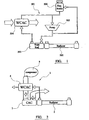
- the arrangement shown in Figure 1 represents a prior art automotive heat exchanger system 501 which includes a primary engine cooling circuit including a radiator 502 (the primary circuit line is not shown in Figure 1). Additionally, the system includes a supplementary circuit including a supplementary radiator 503 for supplying coolant liquid (water) to pass through a water cooled charge air cooler 504. Compressed charge air passes through water cooled charge air cooler 504 where heat transfer occurs and lower temperature charge air exits.
- the supplementary coolant circuit, in addition to supplementary radiator 503 and water cooled charge air cooler 504 includes a separate pump 505 and expansion vessel 506.
- Such prior art systems are becoming used in large vehicles, where there is a current trend for turbo charge pressure and temperature to be increased.
- a prior art system such as that described in Figure 1 using alternatively a water cooled charge air cooler 504 is capable of heat dissipation in the region of 25 Kw.
- a disadvantage of the system shown in Figure 1 is that the supplementary circuit for supplying the water cooled charge air cooler 504 including the pump and expansion vessel 506 in addition to the supplementary radiator 503 takes up space in the vehicle engine compartment. In the automotive industry, particularly in respect of lower end of market vehicles, which have smaller engine compartment cavities, space is at a premium.
- the present invention utilises the primary engine coolant circuit including the primary radiator 2 to provide liquid coolant to a two stage charge air cooling arrangement.
- the two stage charge air cooling arrangement 1 comprises a water cooled charge air cooler stage 4 fed directly from the low temperature end of the primary radiator 2. The charge air is subsequently ducted through an air charge air cooler stage 7. The charge air from compressor 8 is therefore directed first through the water cooled charge air cooler stage 4 and subsequently through the air cooled charge air cooler stage 7, the air cooled charge air cooler 7 is mounted, in the embodiment shown in Figure 2, immediately adjacent the primary engine coolant radiator 2.
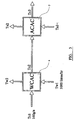
- FIG 3 shows a system diagram in which Tc1 represents the high temperature charge air inlet into the water cooled charge air cooler 4 and Tc2 represents the temperature drop temperature of the charge air exiting stage 4.
- Tw1 represents the inlet temperature of the primary radiator exited engine coolant entering stage 4 and Tw2 represents the elevated temperature of the coolant exiting stage 4.
- Tc2 is also the temperature of the inlet charge air into the air cooled charge air cooler stage 7 and Tc3 represents the subsequently cooled charge air temperature on exit from stage 7.
- Tal represents the air temperature entering the air cooled charge air cooler stage 7, and Ta2 represents the air temperature upon exit.
- the work done by water cooled charge air cooler 4 in reducing temperature Tc1 down to Tc2 is taken up by the engine coolant Tw2.
- the primary system radiator 2 is therefore required to do more work in dissipation of heat from engine coolant flowing in the engine coolant circuit.
- An aspect of the invention is that the additional heat represented at Tw2 in the engine coolant circuit can be directed to other devices (heating ventilation and air conditioning devices, or others in the general automotive system) for dissipation in order to reduce the workload on primary radiator 2.
- the coolant leaving water cooled charge air cooler stage 4 (Tw2) could be directed to cabin air heater of a heat exchanger type, in order to use the additional heat to heat the cabin, where required.
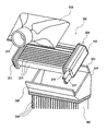
- heat exchanger system 201 comprising liquid cooled charge air cooler 204 supplied with engine coolant from the "cool side" outlet of the primary vehicle engine coolant radiator.
- the liquid cooled charge air cooler 204 comprises a pair of spaced headers 211, 212 and extending, intermediately therebetween, a plurality of spaced heat exchanger tubes 213. The spaces between the tubes provide air flow passageways for the transit across the liquid cooled charge air cooler 204 of charge air, which is directed into the system via duct 215 and shroud 216.
- the cooler 204 is provided with a liquid (water) inlet 217 supplying engine coolant from the primary vehicle radiator "cool side".
- Cooler 204 is provided with a liquid coolant (water) outlet 218 connected back into the vehicle primary coolant circuit, and which preferably permits high temperature coolant exiting from cooler 204 to be directed to other heat dissipation devices in the circuit (such as for example cabin air heaters of the heat exchanger variety).
- a liquid coolant (water) outlet 218 connected back into the vehicle primary coolant circuit, and which preferably permits high temperature coolant exiting from cooler 204 to be directed to other heat dissipation devices in the circuit (such as for example cabin air heaters of the heat exchanger variety).
- An air flow diverter duct 219 is provided with flange elements 220, 221 for locating and mounting the liquid cooled charge air cooler 204.
- Shroud 216 and duct 219 effectively comprise a charge air inlet header for the air cooled charge air cooler stage 207.
- the liquid cooled charge air cooler 204 is effectively mounted largely within the header formed by shroud 216 and duct 219.
- Air flow diverter 219 diverts charge air which has transited through the liquid cooled charge air cooler 204 to be directed into air cooled charge air cooler 207, the construction and arrangement of air cooled charge air cooler 207 may conform largely to the construction arrangement of prior art air cooled charge air coolers, in that air is ducted via a series of spaced charge air carrying heat exchange tubes 210 to an outlet charge air header (not shown) subsequently passing further along the charge air circuit. As the vehicle moves, coolant air passes between the heat exchange tubes 210 providing cooling for the charge air constrained within tubes 210.
- the heat exchanger arrangement 201 may be fabricated in a one shot fusing/bonding process such as for example a one shot brazing process where the components comprise aluminium or aluminium alloy clad with suitable brazing alloy (for example).
- the stages 204 and 207 may be fabricated separately (for example again in a fusion process such as brazing) and subsequently joined to the shroud 216 and air flow diverter 219 by mechanical clenching or other joining means.
- the two stage heat exchanger arrangement 301 is generally similar to the arrangement shown in Figures 4 and 5; however, in this embodiment, the liquid cooled charge air cooler 304 provided with headers 311, 312 and turned through 90°, as are the heat exchange tubes 313 connecting headers 311 and 312. This provides that the heat exchange tubes 313 for the liquid cooled charge air cooler stage 304 can match up and correspond (lie parallel) with the heat exchange tube 310 spacing for the air cooled charge air cooler 307. This provides more uniform flow of charge air transiting the liquid cooled stage 304 and entering the air cooled stage 307.
- Engine coolant inlet 317 and outlet 318 for the liquid cooled stage 304 are provided in header 312.
- Flanges 320, 312 are provided at opposed side ends of the arrangement.
- a major benefit of the present invention is that because the water cooled charge air cooler stage does not require a supplementary radiator or pump arrangement, less space is required within the vehicle engine department. This is a significant benefit.
- a liquid cooled charge air cooler stage 404 which includes a pair of spaced annular headers 411, 412 provided with a liquid (water) coolant inlet 417 and outlet 418. Extending between headers 411, 412 is an annular water jacket 413, the inner void of annular water jacket 413 defining a cylindrical charge air flow passage. The charge air flows between charge air inlet (arrow A) and charge air outlet (arrow B).
- the annular coolant jacket 413 includes a plurality of discrete longitudinally running channels 450.
- the interior charge air void of annular jacket 413 includes a vane system 453 for directing the flow of charge air in the longitudinal direction of the cooler.
- the invention therefore provides a liquid cooled charge air cooler comprising a charge air carrying duct extending between an inlet and an outlet, a liquid coolant jacket extending about the periphery of the charge air carrying duct.
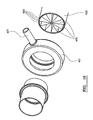
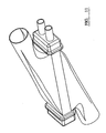
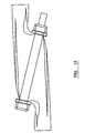
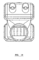
- FIG. 11 to 14 there is shown a further alternative embodiment of a liquid cooled charge air cooler 604 which may be used in a system in accordance with the invention.
- the liquid cooled charge air cooler unit 604 is generally similar to the arrangement shown in Figure 5, including a pair of spaced headers 611, 612, an inlet 617 fed by the engine coolant circuit downstream of the "cool end" of the primary engine coolant radiator and an engine coolant outlet 618. Intermediate headers 611, 612 extend space heat exchanger tubes 613. Inlet and outlet shrouds 616, 660 close over the array of spaced heat exchange tubes 613 to define the diverging inlet 616 into the stage 604, and a converging outlet 660 out of the stage 604 respectively.
- the inlet 616a and outlet 660a include neck portions angled to ensure that the inlet charge air flow and outlet charge air flow is in a substantially common direction. This has been found to improve performance.
- the invention therefore provides a liquid cooled charge air cooler comprising charge air cooler core including a plurality of spaced tubes arranged to carry a heat transfer coolant liquid, the space between adjacent tubes defining an air flow matrix for flow of charge air through the stage; inlet and outlet shrouds directing charge air into and out of the charge air cooler core to pass between the spaced heat exchanger tubes, the inlet and outlet shrouds including neck portions inclined correspondingly to provide a substantially common charge air inlet direction and charge air outlet direction, wherein the transverse direction across the charge air cooler core is not in line with the substantially in line inlet and outlet charge air directions.
Landscapes
- Engineering & Computer Science (AREA)
- Mechanical Engineering (AREA)
- General Engineering & Computer Science (AREA)
- Physics & Mathematics (AREA)
- Thermal Sciences (AREA)
- Chemical & Material Sciences (AREA)
- Combustion & Propulsion (AREA)
- Heat-Exchange Devices With Radiators And Conduit Assemblies (AREA)
- Filling Or Discharging Of Gas Storage Vessels (AREA)
- Transition And Organic Metals Composition Catalysts For Addition Polymerization (AREA)
- Separation Using Semi-Permeable Membranes (AREA)
- Cooling, Air Intake And Gas Exhaust, And Fuel Tank Arrangements In Propulsion Units (AREA)
Claims (12)
- Automotives System
mit einem Flüssigkeitskühlkreis, das Motorkühlmittel führt, wobei der Flüssigkeitskühlkreis eine Kühleranordnung (2) zum Abführen von Wärme aus dem Motorkühlmittel aufweist;
mit einem Ladeluft-Zuführsystem zum Zuführen von Ladeluft aus einer Kompressoranordnung (8) an eine Antriebskraftmaschine;
mit einer zweistufigen Wärmetauscheranordnung, die auf die Ladeluft einwirkt und die Folgendes enthält:eine erste, flüssigkeitsgekühlte Wärmetauscherstufe (4), die ein Strömungspfadsystem für den Durchfluss von Ladeluft aufweist und, gegenüber diesem abgedichtet, ein Strömungspfadsystem für den Durchfluss von Kühlflüssigkeit, die die Stromaufwärtsseite der Kühleranordnung verläßt;eine zweite, gasgekühlte Wärmetauscherstufe (7), die stromabwärts der ersten Stufe in dem Ladeluftsystem angeordnet ist und die ein Strömungspfadsystem für den Durchfluss von Ladeluft aufweist und, gegenüber diesem abgedichtet, ein Strömungspfadsystem zum Leiten von Kühlgas;dadurch gekennzeichnet,
dass zumindest ein Teil der Kühlflüssigkeit, die den Ladeluftwärmetauscher verlässt, so geführt wird, dass sie in der Lage ist, das Aufwärmen der Kabine zu unterstützen. - System nach Anspruch 1, dadurch gekennzeichnet, dass die Kühleranordnung (2) in dem Motorkühlflüssiqkeitskreis den primären Kühler als das primäre Mittel benutzt, um Wärme von der Motorkühlflüssigkeit abzuführen.
- System nach einem oder mehreren der vorhergehenden Ansprüche, dadurch gekennzeichnet, dass zumindest ein Teil der Kühlflüssigkeit einer Kabinenheizungseinrichtung zugeführt wird.
- System nach einem oder mehreren der vorhergehenden Ansprüche, dadurch gekennzeichnet, dass die zweite (gasgekühlte) Stufe (7) durch Luft gekühlt wird.
- System nach Anspruch 4, dadurch gekennzeichnet, dass die zweite (gasgekühlte) Stufe (7) durch Umgebungsluft gekühlt wird.
- System nach einem oder mehreren der vorhergehenden Ansprüche, dadurch gekennzeichnet, dass die erste (4) und die zweite (7) Stufe in einer integrierten Einheit kombiniert sind und dass Ladeluft von der ersten Stufe unmittelbar in das Ladeluft-Strömungssystem der zweiten Stufe (7) geleitet wird.
- System nach einem oder mehreren der vorhergehenden Ansprüche, dadurch gekennzeichnet, dass ein verbindendes Luftführungselement vorgesehen ist, um den Ladeluftstrom zwischen der ersten (4) und der zweiten (7) Stufe zu führen.
- System nach Anspruch 7, dadurch gekennzeichnet, dass das Luftführungselement so geformt oder ausgebildet ist, dass es die Flussrichtung der Ladeluft zwischen der ersten (4) und der zweiten (7) Stufe umleitet.
- System nach Anspruch 7 oder 8, dadurch gekennzeichnet, dass das verbindende Luftführungselement mit den Komponenten der ersten (4) und/oder der zweiten Wärmetauscherstufe (7) zusammenwirkt und diese in Position hält.
- System nach einem oder mehreren der vorhergehenden Ansprüche, dadurch gekennzeichnet, dass die erste (4) und die zweite (7) Stufe in einer integrierten Einheit kombiniert sind und Ladeluft von der ersten Stufe (4) in das Ladeluft-Strömungssystem der zweiten Stufe (7) geleitet wird, und dass die erste (4) und die zweite (7) Stufe in einem einzigen Lötvorgang (fusing process) zu der integrierten Einheit verlötet (fused) sind.
- System nach Anspruch 10, dadurch gekennzeichnet, dass die erste (4) und die zweite (7) Stufe in einem einzigen Hartlötvorgang zu der integrierten Einheit hart verlötet sind.
- System nach einem oder mehreren der Ansprüche 1 bis 9, dadurch gekennzeichnet, dass die erste (4) und die zweite (7) Stufe in einer integrierten Einheit kombiniert sind und Ladeluft von der ersten Stufe (4) unmittelbar in das Ladeluft-Strömungssystem der zweiten Stufe (7) geleitet wird, und dass die erste (4) und die zweite (7) Stufe zu einer zweiteiligen Anordnung durch Zusammenpressen oder andere mechanische Mittel kombiniert sind.
Applications Claiming Priority (3)
| Application Number | Priority Date | Filing Date | Title |
|---|---|---|---|
| GB0111533 | 2001-05-10 | ||
| GB0111533A GB2375388A (en) | 2001-05-10 | 2001-05-10 | Heat exchanger arrangement for charge air |
| PCT/GB2002/002068 WO2002090739A1 (en) | 2001-05-10 | 2002-05-03 | Automotive system including charge air delivery |
Publications (2)
| Publication Number | Publication Date |
|---|---|
| EP1386068A1 EP1386068A1 (de) | 2004-02-04 |
| EP1386068B1 true EP1386068B1 (de) | 2008-01-09 |
Family
ID=9914451
Family Applications (1)
| Application Number | Title | Priority Date | Filing Date |
|---|---|---|---|
| EP02718409A Expired - Lifetime EP1386068B1 (de) | 2001-05-10 | 2002-05-03 | Ladeluftkühler |
Country Status (5)
| Country | Link |
|---|---|
| EP (1) | EP1386068B1 (de) |
| AT (1) | ATE383503T1 (de) |
| DE (1) | DE60224522T2 (de) |
| GB (1) | GB2375388A (de) |
| WO (1) | WO2002090739A1 (de) |
Cited By (1)
| Publication number | Priority date | Publication date | Assignee | Title |
|---|---|---|---|---|
| DE102018106936A1 (de) | 2018-03-23 | 2019-09-26 | Hanon Systems | Ladeluftkühler aus einem flüssigkeitsgekühlten Vorkühler und einem luftgekühlten Hauptkühler |
Families Citing this family (21)
| Publication number | Priority date | Publication date | Assignee | Title |
|---|---|---|---|---|
| DE10254016A1 (de) * | 2002-11-19 | 2004-06-03 | Behr Gmbh & Co. Kg | Vorrichtung zur Kühlung von Ladeluft und Verfahren zum Betreiben einer derartigen Vorrichtung |
| AU2003202463B1 (en) * | 2003-03-26 | 2004-02-26 | Sun Chan | Heat exchanger |
| DE102004001462A1 (de) * | 2004-01-08 | 2005-08-18 | Behr Gmbh & Co. Kg | Kühlsystem |
| DE102004018000A1 (de) * | 2004-04-14 | 2005-11-10 | Dr.Ing.H.C. F. Porsche Ag | Ladeluftkühler |
| US7165537B2 (en) * | 2004-11-10 | 2007-01-23 | Honeywell International Inc. | Charge air cooler |
| NL1027948C2 (nl) * | 2005-01-04 | 2006-07-05 | Eindhovense Radiateurenfabriek | Koelinrichting. |
| SE528198C2 (sv) * | 2005-02-21 | 2006-09-26 | Scania Cv Ab | Laddluftkylare |
| EP1849989A1 (de) | 2006-04-26 | 2007-10-31 | Daf Trucks N.V. | Kanal zur Verbindung eines Verdichters und eines Zwischenkühlers |
| DE102006032205A1 (de) * | 2006-07-12 | 2008-01-17 | Modine Manufacturing Co., Racine | Wärmetauscher mit Kupplungsanschluss und Kupplungsanschluss |
| DE202007002169U1 (de) * | 2007-02-09 | 2008-06-26 | Mann + Hummel Gmbh | Ladeluftkühler |
| EP2138702A1 (de) * | 2008-06-25 | 2009-12-30 | Magneti Marelli Powertrain S.p.A. | Einlasssystem für Verbrennungsmotoren |
| JP5029547B2 (ja) * | 2008-09-15 | 2012-09-19 | 株式会社デンソー | 吸気冷却システム |
| WO2010079796A1 (ja) * | 2009-01-09 | 2010-07-15 | カルソニックカンセイ株式会社 | 複合型熱交換器 |
| FR2968719B1 (fr) * | 2010-12-10 | 2012-12-21 | Valeo Systemes Thermiques | Dispositif de canalisation d'un flux de gaz d'alimentation d'un moteur a combustion interne |
| DE102011003248A1 (de) | 2011-01-27 | 2012-08-02 | Bayerische Motoren Werke Aktiengesellschaft | Wärmetauscher |
| GB2501304B (en) | 2012-04-19 | 2019-01-16 | Ford Global Tech Llc | Apparatus and method for engine warm up |
| FR2997487B1 (fr) * | 2012-10-26 | 2018-07-27 | Valeo Systemes Thermiques | Boite collectrice pour echangeur de chaleur, notamment refroidisseur d'air de suralimentation de moteur de vehicule automobile |
| GB2534900A (en) * | 2015-02-04 | 2016-08-10 | Gm Global Tech Operations Llc | Internal combustion engine having a charge cooling system for a two stage turbocharger |
| DE102017107134A1 (de) * | 2017-04-03 | 2018-10-04 | Dr. Ing. H.C. F. Porsche Aktiengesellschaft | Wärmetauscher für Hochtemperatur-Anwendung, insbesondere Ladeluftkühler |
| CN115298417B (zh) | 2020-03-23 | 2025-10-17 | 康明斯公司 | 多芯热回收增压冷却器 |
| WO2024170933A1 (en) * | 2023-02-15 | 2024-08-22 | Volvo Truck Corporation | Cab heating utilizing the waste heat recovered using the charged air from the turbo outlet before a charge air cooler inlet |
Citations (2)
| Publication number | Priority date | Publication date | Assignee | Title |
|---|---|---|---|---|
| US4236492A (en) * | 1976-12-04 | 1980-12-02 | Klockner-Humboldt-Deutz Aktiengesellschaft | Internal combustion engine having a supercharger and means for cooling charged air |
| JPS59224414A (ja) * | 1983-06-01 | 1984-12-17 | Toyota Motor Corp | タ−ボチヤ−ジヤ付内燃機関の冷却装置 |
Family Cites Families (5)
| Publication number | Priority date | Publication date | Assignee | Title |
|---|---|---|---|---|
| JPS59145325A (ja) * | 1983-02-08 | 1984-08-20 | Toyo Radiator Kk | 車両、又は船舶の過給器用熱交換器のタンク構造 |
| US5036668A (en) * | 1990-07-03 | 1991-08-06 | Allied-Signal Inc. | Engine intake temperature control system |
| ES2049154B1 (es) * | 1991-12-03 | 1995-02-16 | Pascual Juann Targa | Cambiador de calor mixto para circuitos de admision de aire en motores de combustion interna. |
| DE19727277A1 (de) * | 1997-06-27 | 1999-01-07 | Iav Motor Gmbh | Einrichtung zur Konditionierung der Ladeluft, vorzugsweise für Otto-Motoren mit Direkteinspritzung und Abgasturbolader |
| DE19849619B4 (de) * | 1998-10-28 | 2004-11-18 | Daimlerchrysler Ag | Kühlsystem für einen Verbrennungsmotor eines Kraftfahrzeuges |
-
2001
- 2001-05-10 GB GB0111533A patent/GB2375388A/en not_active Withdrawn
-
2002
- 2002-05-03 EP EP02718409A patent/EP1386068B1/de not_active Expired - Lifetime
- 2002-05-03 DE DE60224522T patent/DE60224522T2/de not_active Expired - Lifetime
- 2002-05-03 AT AT02718409T patent/ATE383503T1/de not_active IP Right Cessation
- 2002-05-03 WO PCT/GB2002/002068 patent/WO2002090739A1/en not_active Ceased
Patent Citations (2)
| Publication number | Priority date | Publication date | Assignee | Title |
|---|---|---|---|---|
| US4236492A (en) * | 1976-12-04 | 1980-12-02 | Klockner-Humboldt-Deutz Aktiengesellschaft | Internal combustion engine having a supercharger and means for cooling charged air |
| JPS59224414A (ja) * | 1983-06-01 | 1984-12-17 | Toyota Motor Corp | タ−ボチヤ−ジヤ付内燃機関の冷却装置 |
Cited By (1)
| Publication number | Priority date | Publication date | Assignee | Title |
|---|---|---|---|---|
| DE102018106936A1 (de) | 2018-03-23 | 2019-09-26 | Hanon Systems | Ladeluftkühler aus einem flüssigkeitsgekühlten Vorkühler und einem luftgekühlten Hauptkühler |
Also Published As
| Publication number | Publication date |
|---|---|
| GB2375388A (en) | 2002-11-13 |
| GB0111533D0 (en) | 2001-07-04 |
| ATE383503T1 (de) | 2008-01-15 |
| DE60224522D1 (de) | 2008-02-21 |
| DE60224522T2 (de) | 2009-01-22 |
| EP1386068A1 (de) | 2004-02-04 |
| WO2002090739A1 (en) | 2002-11-14 |
Similar Documents
| Publication | Publication Date | Title |
|---|---|---|
| EP1386068B1 (de) | Ladeluftkühler | |
| US7631619B2 (en) | Cooling agent compensation tank for a cooling circuit | |
| US6986385B1 (en) | Heating/air conditioning installation for motor vehicle including main module forming fluid-carrying heat exchanger | |
| US6341648B1 (en) | Heat exchanger having heat-exchanging core portion divided into plural core portions | |
| US5794448A (en) | Gas turbine fuel heating apparatus | |
| WO2008015954A1 (en) | Complex heat exchanger and complex heat exchanger system | |
| JP4644485B2 (ja) | 自動車エンジン用冷却モジュール | |
| EP1892492A3 (de) | Wärmetauschermodul, insbesondere für ein Kraftfahrzeug, das einen Haupt- und einen Nebenkühler umfasst, und System, das dieses Modul enthält | |
| US6092383A (en) | Motor vehicle air conditioning device with compact refrigerating loop | |
| JP2009068809A (ja) | ハイブリッド型熱交換器 | |
| EP3271674B1 (de) | Kühlsystem | |
| US8418931B2 (en) | Heat exchanger with integral thermostats | |
| US20040007005A1 (en) | Air conditioning system for marine applications | |
| JPH11237192A (ja) | 内燃機関のegrガスクーラ | |
| US11691498B2 (en) | Vehicle radiator assembly and cooling system having the same | |
| CN100554662C (zh) | 增压空气冷却器 | |
| US6422020B1 (en) | Cast heat exchanger system for gas turbine | |
| JP2017008911A (ja) | 熱交換器 | |
| EP1957926B1 (de) | Wärmetauscheranordnung für einen ladeluftkühler | |
| US11655745B2 (en) | Exhaust gas heat exchanger | |
| US8671669B2 (en) | Exhaust gas cooler for a motor vehicle | |
| EP2037116B1 (de) | Multifunktionsmodul für einen Verbrennungsmotor | |
| US7845392B2 (en) | Heat exchanger assembly | |
| JP4487926B2 (ja) | クーリングモジュール | |
| JP6160527B2 (ja) | 内燃機関のための冷却装置および内燃機関用吸入ガス冷却装置 |
Legal Events
| Date | Code | Title | Description |
|---|---|---|---|
| PUAI | Public reference made under article 153(3) epc to a published international application that has entered the european phase |
Free format text: ORIGINAL CODE: 0009012 |
|
| 17P | Request for examination filed |
Effective date: 20031106 |
|
| AK | Designated contracting states |
Kind code of ref document: A1 Designated state(s): AT BE CH CY DE DK ES FI FR GB GR IE IT LI LU MC NL PT SE TR |
|
| AX | Request for extension of the european patent |
Extension state: AL LT LV MK RO SI |
|
| 17Q | First examination report despatched |
Effective date: 20060906 |
|
| GRAP | Despatch of communication of intention to grant a patent |
Free format text: ORIGINAL CODE: EPIDOSNIGR1 |
|
| GRAS | Grant fee paid |
Free format text: ORIGINAL CODE: EPIDOSNIGR3 |
|
| GRAA | (expected) grant |
Free format text: ORIGINAL CODE: 0009210 |
|
| AK | Designated contracting states |
Kind code of ref document: B1 Designated state(s): AT BE CH CY DE DK ES FI FR GB GR IE IT LI LU MC NL PT SE TR |
|
| REG | Reference to a national code |
Ref country code: GB Ref legal event code: FG4D |
|
| REG | Reference to a national code |
Ref country code: CH Ref legal event code: EP |
|
| REG | Reference to a national code |
Ref country code: IE Ref legal event code: FG4D |
|
| REF | Corresponds to: |
Ref document number: 60224522 Country of ref document: DE Date of ref document: 20080221 Kind code of ref document: P |
|
| PG25 | Lapsed in a contracting state [announced via postgrant information from national office to epo] |
Ref country code: NL Free format text: LAPSE BECAUSE OF FAILURE TO SUBMIT A TRANSLATION OF THE DESCRIPTION OR TO PAY THE FEE WITHIN THE PRESCRIBED TIME-LIMIT Effective date: 20080109 |
|
| NLV1 | Nl: lapsed or annulled due to failure to fulfill the requirements of art. 29p and 29m of the patents act | ||
| PG25 | Lapsed in a contracting state [announced via postgrant information from national office to epo] |
Ref country code: LI Free format text: LAPSE BECAUSE OF FAILURE TO SUBMIT A TRANSLATION OF THE DESCRIPTION OR TO PAY THE FEE WITHIN THE PRESCRIBED TIME-LIMIT Effective date: 20080109 Ref country code: CH Free format text: LAPSE BECAUSE OF FAILURE TO SUBMIT A TRANSLATION OF THE DESCRIPTION OR TO PAY THE FEE WITHIN THE PRESCRIBED TIME-LIMIT Effective date: 20080109 Ref country code: FI Free format text: LAPSE BECAUSE OF FAILURE TO SUBMIT A TRANSLATION OF THE DESCRIPTION OR TO PAY THE FEE WITHIN THE PRESCRIBED TIME-LIMIT Effective date: 20080109 Ref country code: ES Free format text: LAPSE BECAUSE OF FAILURE TO SUBMIT A TRANSLATION OF THE DESCRIPTION OR TO PAY THE FEE WITHIN THE PRESCRIBED TIME-LIMIT Effective date: 20080420 |
|
| REG | Reference to a national code |
Ref country code: CH Ref legal event code: PL |
|
| PG25 | Lapsed in a contracting state [announced via postgrant information from national office to epo] |
Ref country code: AT Free format text: LAPSE BECAUSE OF FAILURE TO SUBMIT A TRANSLATION OF THE DESCRIPTION OR TO PAY THE FEE WITHIN THE PRESCRIBED TIME-LIMIT Effective date: 20080109 |
|
| ET | Fr: translation filed | ||
| PG25 | Lapsed in a contracting state [announced via postgrant information from national office to epo] |
Ref country code: BE Free format text: LAPSE BECAUSE OF FAILURE TO SUBMIT A TRANSLATION OF THE DESCRIPTION OR TO PAY THE FEE WITHIN THE PRESCRIBED TIME-LIMIT Effective date: 20080109 Ref country code: PT Free format text: LAPSE BECAUSE OF FAILURE TO SUBMIT A TRANSLATION OF THE DESCRIPTION OR TO PAY THE FEE WITHIN THE PRESCRIBED TIME-LIMIT Effective date: 20080609 |
|
| PG25 | Lapsed in a contracting state [announced via postgrant information from national office to epo] |
Ref country code: SE Free format text: LAPSE BECAUSE OF FAILURE TO SUBMIT A TRANSLATION OF THE DESCRIPTION OR TO PAY THE FEE WITHIN THE PRESCRIBED TIME-LIMIT Effective date: 20080409 Ref country code: DK Free format text: LAPSE BECAUSE OF FAILURE TO SUBMIT A TRANSLATION OF THE DESCRIPTION OR TO PAY THE FEE WITHIN THE PRESCRIBED TIME-LIMIT Effective date: 20080109 |
|
| PLBE | No opposition filed within time limit |
Free format text: ORIGINAL CODE: 0009261 |
|
| STAA | Information on the status of an ep patent application or granted ep patent |
Free format text: STATUS: NO OPPOSITION FILED WITHIN TIME LIMIT |
|
| 26N | No opposition filed |
Effective date: 20081010 |
|
| PG25 | Lapsed in a contracting state [announced via postgrant information from national office to epo] |
Ref country code: MC Free format text: LAPSE BECAUSE OF NON-PAYMENT OF DUE FEES Effective date: 20080531 |
|
| PG25 | Lapsed in a contracting state [announced via postgrant information from national office to epo] |
Ref country code: IE Free format text: LAPSE BECAUSE OF NON-PAYMENT OF DUE FEES Effective date: 20080505 |
|
| PG25 | Lapsed in a contracting state [announced via postgrant information from national office to epo] |
Ref country code: CY Free format text: LAPSE BECAUSE OF FAILURE TO SUBMIT A TRANSLATION OF THE DESCRIPTION OR TO PAY THE FEE WITHIN THE PRESCRIBED TIME-LIMIT Effective date: 20080109 |
|
| PG25 | Lapsed in a contracting state [announced via postgrant information from national office to epo] |
Ref country code: IT Free format text: LAPSE BECAUSE OF FAILURE TO SUBMIT A TRANSLATION OF THE DESCRIPTION OR TO PAY THE FEE WITHIN THE PRESCRIBED TIME-LIMIT Effective date: 20080109 |
|
| PG25 | Lapsed in a contracting state [announced via postgrant information from national office to epo] |
Ref country code: LU Free format text: LAPSE BECAUSE OF NON-PAYMENT OF DUE FEES Effective date: 20080503 |
|
| PG25 | Lapsed in a contracting state [announced via postgrant information from national office to epo] |
Ref country code: TR Free format text: LAPSE BECAUSE OF FAILURE TO SUBMIT A TRANSLATION OF THE DESCRIPTION OR TO PAY THE FEE WITHIN THE PRESCRIBED TIME-LIMIT Effective date: 20080109 |
|
| PG25 | Lapsed in a contracting state [announced via postgrant information from national office to epo] |
Ref country code: GR Free format text: LAPSE BECAUSE OF FAILURE TO SUBMIT A TRANSLATION OF THE DESCRIPTION OR TO PAY THE FEE WITHIN THE PRESCRIBED TIME-LIMIT Effective date: 20080410 |
|
| REG | Reference to a national code |
Ref country code: FR Ref legal event code: PLFP Year of fee payment: 15 |
|
| REG | Reference to a national code |
Ref country code: FR Ref legal event code: PLFP Year of fee payment: 16 |
|
| REG | Reference to a national code |
Ref country code: FR Ref legal event code: PLFP Year of fee payment: 17 |
|
| PGFP | Annual fee paid to national office [announced via postgrant information from national office to epo] |
Ref country code: DE Payment date: 20180522 Year of fee payment: 17 |
|
| PGFP | Annual fee paid to national office [announced via postgrant information from national office to epo] |
Ref country code: FR Payment date: 20180522 Year of fee payment: 17 |
|
| PGFP | Annual fee paid to national office [announced via postgrant information from national office to epo] |
Ref country code: GB Payment date: 20180405 Year of fee payment: 17 |
|
| REG | Reference to a national code |
Ref country code: DE Ref legal event code: R119 Ref document number: 60224522 Country of ref document: DE |
|
| GBPC | Gb: european patent ceased through non-payment of renewal fee |
Effective date: 20190503 |
|
| PG25 | Lapsed in a contracting state [announced via postgrant information from national office to epo] |
Ref country code: GB Free format text: LAPSE BECAUSE OF NON-PAYMENT OF DUE FEES Effective date: 20190503 Ref country code: DE Free format text: LAPSE BECAUSE OF NON-PAYMENT OF DUE FEES Effective date: 20191203 |
|
| PG25 | Lapsed in a contracting state [announced via postgrant information from national office to epo] |
Ref country code: FR Free format text: LAPSE BECAUSE OF NON-PAYMENT OF DUE FEES Effective date: 20190531 |