EP1387063A2 - Système d'échappement pour un moteur à combustion interne - Google Patents
Système d'échappement pour un moteur à combustion interne Download PDFInfo
- Publication number
- EP1387063A2 EP1387063A2 EP03017305A EP03017305A EP1387063A2 EP 1387063 A2 EP1387063 A2 EP 1387063A2 EP 03017305 A EP03017305 A EP 03017305A EP 03017305 A EP03017305 A EP 03017305A EP 1387063 A2 EP1387063 A2 EP 1387063A2
- Authority
- EP
- European Patent Office
- Prior art keywords
- lever
- flap
- exhaust system
- flow
- exhaust gas
- Prior art date
- Legal status (The legal status is an assumption and is not a legal conclusion. Google has not performed a legal analysis and makes no representation as to the accuracy of the status listed.)
- Withdrawn
Links
Images

Classifications
-
- F—MECHANICAL ENGINEERING; LIGHTING; HEATING; WEAPONS; BLASTING
- F02—COMBUSTION ENGINES; HOT-GAS OR COMBUSTION-PRODUCT ENGINE PLANTS
- F02D—CONTROLLING COMBUSTION ENGINES
- F02D11/00—Arrangements for, or adaptations to, non-automatic engine control initiation means, e.g. operator initiated
- F02D11/04—Arrangements for, or adaptations to, non-automatic engine control initiation means, e.g. operator initiated characterised by mechanical control linkages
-
- F—MECHANICAL ENGINEERING; LIGHTING; HEATING; WEAPONS; BLASTING
- F01—MACHINES OR ENGINES IN GENERAL; ENGINE PLANTS IN GENERAL; STEAM ENGINES
- F01N—GAS-FLOW SILENCERS OR EXHAUST APPARATUS FOR MACHINES OR ENGINES IN GENERAL; GAS-FLOW SILENCERS OR EXHAUST APPARATUS FOR INTERNAL-COMBUSTION ENGINES
- F01N13/00—Exhaust or silencing apparatus characterised by constructional features
- F01N13/011—Exhaust or silencing apparatus characterised by constructional features having two or more purifying devices arranged in parallel
-
- F—MECHANICAL ENGINEERING; LIGHTING; HEATING; WEAPONS; BLASTING
- F02—COMBUSTION ENGINES; HOT-GAS OR COMBUSTION-PRODUCT ENGINE PLANTS
- F02B—INTERNAL-COMBUSTION PISTON ENGINES; COMBUSTION ENGINES IN GENERAL
- F02B37/00—Engines characterised by provision of pumps driven at least for part of the time by exhaust
- F02B37/004—Engines characterised by provision of pumps driven at least for part of the time by exhaust with exhaust drives arranged in series
-
- F—MECHANICAL ENGINEERING; LIGHTING; HEATING; WEAPONS; BLASTING
- F02—COMBUSTION ENGINES; HOT-GAS OR COMBUSTION-PRODUCT ENGINE PLANTS
- F02B—INTERNAL-COMBUSTION PISTON ENGINES; COMBUSTION ENGINES IN GENERAL
- F02B37/00—Engines characterised by provision of pumps driven at least for part of the time by exhaust
- F02B37/013—Engines characterised by provision of pumps driven at least for part of the time by exhaust with exhaust-driven pumps arranged in series
-
- F—MECHANICAL ENGINEERING; LIGHTING; HEATING; WEAPONS; BLASTING
- F02—COMBUSTION ENGINES; HOT-GAS OR COMBUSTION-PRODUCT ENGINE PLANTS
- F02B—INTERNAL-COMBUSTION PISTON ENGINES; COMBUSTION ENGINES IN GENERAL
- F02B37/00—Engines characterised by provision of pumps driven at least for part of the time by exhaust
- F02B37/12—Control of the pumps
- F02B37/18—Control of the pumps by bypassing exhaust from the inlet to the outlet of turbine or to the atmosphere
- F02B37/183—Arrangements of bypass valves or actuators therefor
- F02B37/186—Arrangements of actuators or linkage for bypass valves
-
- F—MECHANICAL ENGINEERING; LIGHTING; HEATING; WEAPONS; BLASTING
- F02—COMBUSTION ENGINES; HOT-GAS OR COMBUSTION-PRODUCT ENGINE PLANTS
- F02D—CONTROLLING COMBUSTION ENGINES
- F02D9/00—Controlling engines by throttling air or fuel-and-air induction conduits or exhaust conduits
- F02D9/04—Controlling engines by throttling air or fuel-and-air induction conduits or exhaust conduits concerning exhaust conduits
-
- F—MECHANICAL ENGINEERING; LIGHTING; HEATING; WEAPONS; BLASTING
- F02—COMBUSTION ENGINES; HOT-GAS OR COMBUSTION-PRODUCT ENGINE PLANTS
- F02D—CONTROLLING COMBUSTION ENGINES
- F02D9/00—Controlling engines by throttling air or fuel-and-air induction conduits or exhaust conduits
- F02D9/08—Throttle valves specially adapted therefor; Arrangements of such valves in conduits
- F02D9/10—Throttle valves specially adapted therefor; Arrangements of such valves in conduits having pivotally-mounted flaps
-
- F—MECHANICAL ENGINEERING; LIGHTING; HEATING; WEAPONS; BLASTING
- F01—MACHINES OR ENGINES IN GENERAL; ENGINE PLANTS IN GENERAL; STEAM ENGINES
- F01N—GAS-FLOW SILENCERS OR EXHAUST APPARATUS FOR MACHINES OR ENGINES IN GENERAL; GAS-FLOW SILENCERS OR EXHAUST APPARATUS FOR INTERNAL-COMBUSTION ENGINES
- F01N13/00—Exhaust or silencing apparatus characterised by constructional features
- F01N13/08—Other arrangements or adaptations of exhaust conduits
- F01N13/10—Other arrangements or adaptations of exhaust conduits of exhaust manifolds
- F01N13/107—More than one exhaust manifold or exhaust collector
-
- Y—GENERAL TAGGING OF NEW TECHNOLOGICAL DEVELOPMENTS; GENERAL TAGGING OF CROSS-SECTIONAL TECHNOLOGIES SPANNING OVER SEVERAL SECTIONS OF THE IPC; TECHNICAL SUBJECTS COVERED BY FORMER USPC CROSS-REFERENCE ART COLLECTIONS [XRACs] AND DIGESTS
- Y02—TECHNOLOGIES OR APPLICATIONS FOR MITIGATION OR ADAPTATION AGAINST CLIMATE CHANGE
- Y02T—CLIMATE CHANGE MITIGATION TECHNOLOGIES RELATED TO TRANSPORTATION
- Y02T10/00—Road transport of goods or passengers
- Y02T10/10—Internal combustion engine [ICE] based vehicles
- Y02T10/12—Improving ICE efficiencies
Definitions
- the invention relates to an exhaust system for an internal combustion engine according to the specified in the preamble of claim 1 Features.
- the power output of an internal combustion engine is proportional the air flow, which in turn is proportional to the air density is, so that the performance is known at the same stroke volume and speed by pre-compression of the air before entry into the cylinder (s), i. by charging, increased can be.
- This charge can be through an exhaust gas turbocharger take place, which consists of two rotatably substantially together connected turbomachinery consists.
- a turbine is arranged in an exhaust pipe of the internal combustion engine and is driven by the exhaust gas flow. The turbine drives over one rotatable connection of a supercharger shaft to the compressor, which in the inlet line to the internal combustion engine, a boost pressure generated.
- Such an exhaust gas turbocharger is known from the book "Exhaust turbocharger, page 36 - 39, author Michael Mayer, Verlag Moderne Industrie, Landsberg / Lech, 4th edition, 2001".
- the boost pressure control is performed here by a bypass on the turbine side, in which part of the exhaust gas quantity is conducted around the turbine.
- the wastegate which opens and closes the bypass, is controlled by a spring-loaded diaphragm depending on the boost pressure.
- the diaphragm which is preloaded by a cylindrical helical spring, is charged with boost pressure in the control can. Once the bias of the spring is overcome by the boost pressure, the bypass valve is opened by means of the control rod and the adjusting lever.
- the object of the invention is therefore to provide an exhaust system for a Internal combustion engine available, despite smaller Actuator a large swivel range of the flow flaps and at the same time the flow flaps against safe closes the applied gas pressure.
- an exhaust system for an internal combustion engine comprising at least one flow flap and at least one actuator, wherein between the flow flap and the actuator unit a lever device is arranged to implement a movement of the actuator in a movement of the flow flap.
- the lever device further includes a pull or push rod connected to the actuator and a shaft, wherein the flow flap and a first lever are rigidly connected to each other via this shaft.
- the free end of the first lever also has a hinge.
- the lever device further comprises at least one further lever and a Hohebelarmige baffle with 3 hinge axes or articulation points, which are arranged in the form of a triangle on the baffle plate.
- the baffle plate is designed as a two-armed baffle.
- a very advantageous development of the invention also consists in that one of the joint axes or articulation points of the baffle plate is designed as a rigid pivot about which the other two axes can rotate on a circular path.
- the at least one further lever at one end via a hinge is rotatably connected to the first lever, at the other end via a hinge rotatably connected to the baffle.
- the actuator may be formed as a further advantage as a pressure box, which is operable with positive or negative pressure.
- the actuator according to the invention can also be designed as an electrical, electromechanical or hydraulic drive.
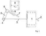
- Fig. 1 describes a conventional lever device with an actuator 1, at which there is a positive or negative pressure connection 2 is located.
- the actuator 1 is here as a pressure box educated.
- the canned by a cylindrical Coil spring preloaded diaphragm comes with a Pressure difference (i.e., positive or negative pressure) applied.
- the flow flap 7 which is rigid with the Shaft 6 is connected by means of the pull or push rod.
- the pressure cell 1 and the lever 5 with the train or Push rod 3 connected by a movable joint 4 is opened.
- the adjusting lever 5 is rigid with the shaft. 6 connected. With increasingly open flap one can always larger gas flow pass the flap.
- flap angle 9 is referred to as flap angle 9.
- Figure 1 it is shown that the pull or push rod a Lever moves and creates a moment in the lever axis. It is known that a longer lever in this arrangement a larger Moment can produce, however, with only a smaller one Swivel angle 9.
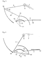
- Fig. 2 shows a possible structural design of the invention Lever device.
- Actuator 1 may preferably be a pressure box be with a pull or push rod 3, the gas pressure (Over or under pressure) is operated and the one device for generating a bias voltage, e.g. a coil spring, may contain.
- actuator 1 other suitable Drives such as electrical, electromechanical, hydraulic or other suitable drives are used.
- the two-armed baffle 10 has a total of 3 Joint axes or articulation points, which in the form of a Triangles are arranged on the baffle plate.
- the baffle plate itself may preferably be in the form of a triangle his.
- other shapes are possible such as all oblong, round, oval, (right) square, V-shaped or other shapes that are suitable are, located on the baffle 3 hinge axes or to cover articulation points areally. these are in addition to the articulation point 11, the pivot points 12 and 13, wherein the point 12 via a joint with the drawbar 3 and the Point 13 about another joint with the at least one another lever 14 is connected.
- the invention now advantageously shows how, in spite of one large swivel angle on the one hand a big moment in the progressive Transfer operation of the flap transferred and the other despite using a small actuator a flow flap can be safely closed with great force.
- a simple Lever instead of a simple Lever according to the invention advantageously a special Arrangement of multiple levers used which makes it possible to realize a large opening angle.
- FIG. 3 Principle drawing a device according to the invention with two Levers and a baffle.
- the actuator 1 provided here as a vacuum box
- the linear movement of the pull or push rod 3 of the vacuum unit 1 is first via a baffle 10, which not shown here explicitly, in a pivoting movement of approximately 90 ° about the hinge axis 11 or the articulation point, which is designed as a rigid pivot, transformed.
- This two-armed baffle 10 has a total of 3 hinge axes or articulation points, which are arranged in the form of a triangle are as shown in Fig. 3 can be seen.
- the positions of the articulation axes or articulation points 12, 13, 15 and 16 are at the transition from the open flap to the closed flap in Figures 3 and 4 by, respectively 33 corresponding points shown.
- the hub of the Pull and push rod from position "to" to position "closed”, i.e. from pivot point 15 to pivot point 15 ', is in 32 equidistant Split sections. Is articulation point 15 e.g. in the position "7th point from the left", then it is the pivot point 12 also at the 7th point from the left on his Circular path.
- the pivot point 13 is the 7th point of his Circular path advanced and thus is also the pivot point 16th calculated on the 7th point of his orbit from above.
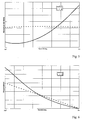
- Fig. 5 describes qualitatively acting on the flap shaft 6 Moment depending on the adjustment, with a A two-armed lever device A according to the invention with a conventional lever device B compared with only one lever becomes.
- inventive Lever A that when closing the flow flap. 7 the maximum available torque on the valve shaft 6 the greater is, the farther the flow flap 7 of the position "too close".
- the effective lever arm is activated the flow flap 7 is getting bigger.
- the course of the effective Lever arm equals the course of the moment on the adjustment.
- the conventional lever device B the moment acting on the flap shaft 6 over the entire adjustment almost constant. This means, that the flow flap 7 is not completely against the gas back pressure close and thus a certain volume flow Gas can escape. This leads to an impairment of the Engine performance.
- Fig. 6 describes the flap angle 9 in dependence of Verstellweges, wherein a two-armed according to the invention Lever A with a conventional lever device B is compared with only one lever.
- Lever A changes the flap angle over the entire adjustment in a nearly constant manner
- lever device A changes the flap angle over the entire adjustment in a nearly constant manner
- the Flow flap at the beginning covers a larger path, depending however, as the flap approaches the "to" position, the more less moves the flap and the more power that can Apply flap for secure closing.
- the opening angle 9 against the conventional levering solution B clearly how out Fig. 6 in the position "open” in a clear manner is.
- the flow flap can be arranged in exhaust systems be, for example in exhaust gas turbocharger systems in Range of exhaust gas flow as a wastegate flap, also as Blow-off valve referred to as a high-pressure bypass valve or similar, in the area of the fresh air flow as fresh air bypass flap, as discharge flap or the like, or in emission control systems as a bypass flap, as a control flap for Circuit of one or more exhaust lines in the exhaust gas purification system or similar.
- exhaust systems be, for example in exhaust gas turbocharger systems in Range of exhaust gas flow as a wastegate flap, also as Blow-off valve referred to as a high-pressure bypass valve or similar, in the area of the fresh air flow as fresh air bypass flap, as discharge flap or the like, or in emission control systems as a bypass flap, as a control flap for Circuit of one or more exhaust lines in the exhaust gas purification system or similar.
- the invention is arranged on an exhaust gas turbocharger system with two-stage charging.
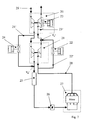
- Fig. 7 shows a possible structure of such exhaust gas turbocharger system. It contains, in addition to an internal combustion engine 27, a low-pressure exhaust gas turbocharger 20 with compressor V N and turbine part T N, a high-pressure turbocharger 21 with compressor V H and turbine part T H, a high-pressure turbine bypass valve with inventive lever device and pneumatic damper drive 22, a blow-off valve or waste gate with inventive lever device and pneumatic flap drive 23, a high-pressure compressor bypass flap with inventive lever device and pneumatic damper drive 24, and a charge air cooler 25 and a throttle valve 26th
- the exhaust gas of the internal combustion engine 27 is guided via the exhaust pipe 28 to the turbine T H of the high-pressure exhaust gas turbocharger 21.
- the high-pressure turbine bypass valve 22 is opened and a part of the exhaust gas mass flow is guided past the turbine T H via the bypass line 22 '.
- the blow-off valve 23 is opened and a portion of the exhaust gas mass flow is conducted past the turbine T N via the bypass line 23 '.
- the air required for combustion is drawn in at point 29 from the compressor V N of the low-pressure exhaust-gas turbocharger 20, compressed and forwarded to the compressor V H of the high-pressure turbocharger 21. There, the air in the compressor V H is further compressed. If the air mass flow arriving at the compressor V H is greater than the maximum permissible air mass flow for the passage of the compressor V H , the high-pressure compressor bypass flap 24 is opened and part of the compressed air is led past the compressor V H via the bypass line 24 '. After the compressor V H , the two air paths, coming from the compressor V H and from the high-pressure compressor bypass valve 24, combine at the point V H '. The reunited air mass flow now passes through the intercooler 25 and the throttle valve 26 in the internal combustion engine 27th
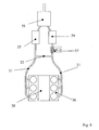
- Figure 8 shows another preferred arrangement of the invention in an exhaust purification system of an internal combustion engine.
- a flow flap with inventive Lever device and pneumatic damper actuator 37 in installed one of the exhaust lines. With the door open, get to it the exhaust gases of the internal combustion engine 30 via the exhaust gas lines 31 or lines and the crosstalk line 32 in the two catalysts 33 and 34. After passing the Silencer 35 will release the exhaust into the atmosphere.
- a part of the cylinder here the page with the cylinder bank 36, turned off, is also the flow flap 37 tight by the lever device according to the invention closed to protect the catalyst 34 from cooling.
Landscapes
- Engineering & Computer Science (AREA)
- Chemical & Material Sciences (AREA)
- Combustion & Propulsion (AREA)
- Mechanical Engineering (AREA)
- General Engineering & Computer Science (AREA)
- Supercharger (AREA)
- Exhaust Silencers (AREA)
Applications Claiming Priority (2)
| Application Number | Priority Date | Filing Date | Title |
|---|---|---|---|
| DE10235528A DE10235528A1 (de) | 2002-08-03 | 2002-08-03 | Abgassystem für eine Brennkraftmaschine |
| DE10235528 | 2002-08-03 |
Publications (2)
| Publication Number | Publication Date |
|---|---|
| EP1387063A2 true EP1387063A2 (fr) | 2004-02-04 |
| EP1387063A3 EP1387063A3 (fr) | 2009-01-28 |
Family
ID=30010575
Family Applications (1)
| Application Number | Title | Priority Date | Filing Date |
|---|---|---|---|
| EP03017305A Withdrawn EP1387063A3 (fr) | 2002-08-03 | 2003-07-31 | Système d'échappement pour un moteur à combustion interne |
Country Status (2)
| Country | Link |
|---|---|
| EP (1) | EP1387063A3 (fr) |
| DE (1) | DE10235528A1 (fr) |
Cited By (13)
| Publication number | Priority date | Publication date | Assignee | Title |
|---|---|---|---|---|
| WO2007083159A1 (fr) * | 2006-01-23 | 2007-07-26 | Lotus Cars Limited | Moteur a combustion interne a deux temps a taux de compression variable et volet d'orifice d'echappement |
| EP2205841A1 (fr) * | 2007-10-29 | 2010-07-14 | Volkswagen Aktiengesellschaft | Moteur à combustion interne comprenant un turbocompresseur à gaz d'échappement et un refroidisseur d'air de suralimentation |
| EP1950388A4 (fr) * | 2005-11-18 | 2010-11-03 | Isuzu Motors Ltd | Systeme de suralimentation a deux etages pour moteur a combustion interne |
| WO2012010252A1 (fr) * | 2010-07-19 | 2012-01-26 | Bayerische Motoren Werke Aktiengesellschaft | Dispositif pour actionner un clapet |
| WO2012110212A1 (fr) * | 2011-02-17 | 2012-08-23 | Ihi Charging Systems International Gmbh | Dispositif d'actionnement pour un turbocompresseur à gaz d'échappement |
| EP2703618A1 (fr) * | 2012-08-31 | 2014-03-05 | Caterpillar Motoren GmbH & Co. KG | Système de commande pour papillons |
| CN103998743A (zh) * | 2011-12-17 | 2014-08-20 | Ihi供应系统国际有限责任公司 | 用于废气涡轮增压器的涡轮机的操纵装置 |
| CN104131882A (zh) * | 2013-04-30 | 2014-11-05 | 株式会社电装 | 阀驱动设备和具有该阀驱动设备的增压器 |
| CN104131885A (zh) * | 2013-04-30 | 2014-11-05 | 株式会社电装 | 阀驱动设备和具有该阀驱动设备的增压器 |
| EP2489853B1 (fr) * | 2011-02-17 | 2016-11-23 | Honeywell International Inc. | Clé de soupape de décharge |
| EP3118434A1 (fr) * | 2015-07-17 | 2017-01-18 | Honeywell International Inc. | Lien pour une soupape de dérivation des agz d'échappement pour un turbocompresseur à plusieurs étages |
| FR3083311A1 (fr) * | 2018-06-28 | 2020-01-03 | Safran Aircraft Engines | Banc de mesure de parametres de fonctionnement d'une porte pivotante de turbomachine |
| US11333064B1 (en) | 2021-05-11 | 2022-05-17 | Garrett Transportation I Inc. | Turbocharger bypass valve and actuator assembly therefor having guided toggle |
Families Citing this family (8)
| Publication number | Priority date | Publication date | Assignee | Title |
|---|---|---|---|---|
| DE102005033601B4 (de) * | 2005-07-14 | 2008-07-03 | Küster Automotive Door Systems GmbH | Elektromechanische Stelleinrichtung für Abgasstauklappe |
| DE102007017828A1 (de) * | 2007-04-16 | 2008-10-23 | Siemens Ag | Turbolader, turboaufgeladene Brennkraftmaschine, Verfahren und Verwendung |
| DE102007026822B4 (de) * | 2007-06-06 | 2010-10-28 | Küster Automotive Control Systems GmbH | Detektionseinrichtung zur Messung der Verstellbewegung einer Abgasstauklappe |
| DE102010004559B4 (de) | 2010-01-14 | 2017-06-01 | Bosch Mahle Turbo Systems Gmbh & Co. Kg | Ladeeinrichtung |
| US8485498B2 (en) * | 2010-06-30 | 2013-07-16 | Denso Corporation | Valve control apparatus |
| JP5299479B2 (ja) * | 2010-06-30 | 2013-09-25 | 株式会社デンソー | バルブ制御装置 |
| DE102015205966A1 (de) * | 2015-04-01 | 2016-10-20 | Volkswagen Aktiengesellschaft | Wastegateventilsystem, Abgasturbolader, Brennkraftmaschine und Kraftfahrzeug |
| DE102021203407A1 (de) | 2021-04-07 | 2022-10-13 | Vitesco Technologies GmbH | Abgasturbolader mit Stellvorrichtung zur Anpassung seines Betriebsverhaltens |
Family Cites Families (9)
| Publication number | Priority date | Publication date | Assignee | Title |
|---|---|---|---|---|
| BE512797A (fr) * | ||||
| GB783900A (en) * | 1955-02-25 | 1957-10-02 | Thomas Ash & Company Ltd | Improvements in or relating to exhaust brakes for vehicles |
| DE2458322C3 (de) * | 1974-12-10 | 1985-04-18 | Eckardt Ag, 7000 Stuttgart | Stellantrieb für Ventile |
| DE7520775U (de) * | 1975-07-01 | 1977-06-30 | Dr.-Ing. H.C. F. Porsche Ag, 7000 Stuttgart | Vorrichtung zur regelung des ladeluftdruckes bei einer mit abgasaufladung betriebenen brennkraftmaschine |
| US4050670A (en) * | 1976-02-05 | 1977-09-27 | Masoneilan International, Inc. | Variable force actuator |
| DE8205873U1 (de) * | 1982-02-26 | 1982-08-12 | Will, Andreas, 1000 Berlin | Absperrvorrichtung fuer rohrleitungen |
| DE3211920A1 (de) * | 1982-03-31 | 1983-10-13 | Klöckner-Humboldt-Deutz AG, 5000 Köln | Einrichtung an einer auspuffbremse |
| DE4321137A1 (de) * | 1993-06-25 | 1995-01-05 | Alfred Schmidt | Auspuffmotorbremse mit Spaltöffnungsstellung |
| DE10027668A1 (de) * | 2000-06-03 | 2001-12-06 | Bosch Gmbh Robert | Vorrichtung zur Steuerung der Verdichterleistung eines an eine Brennkraftmaschine angeschlossenen Abgasturboladers |
-
2002
- 2002-08-03 DE DE10235528A patent/DE10235528A1/de not_active Withdrawn
-
2003
- 2003-07-31 EP EP03017305A patent/EP1387063A3/fr not_active Withdrawn
Cited By (25)
| Publication number | Priority date | Publication date | Assignee | Title |
|---|---|---|---|---|
| EP1950388A4 (fr) * | 2005-11-18 | 2010-11-03 | Isuzu Motors Ltd | Systeme de suralimentation a deux etages pour moteur a combustion interne |
| US8033108B2 (en) | 2005-11-18 | 2011-10-11 | Isuzu Motors Limited | Two-stage supercharging system for internal combustion engine |
| WO2007083159A1 (fr) * | 2006-01-23 | 2007-07-26 | Lotus Cars Limited | Moteur a combustion interne a deux temps a taux de compression variable et volet d'orifice d'echappement |
| EP2205841A1 (fr) * | 2007-10-29 | 2010-07-14 | Volkswagen Aktiengesellschaft | Moteur à combustion interne comprenant un turbocompresseur à gaz d'échappement et un refroidisseur d'air de suralimentation |
| CN102933818B (zh) * | 2010-07-19 | 2015-04-22 | 宝马股份公司 | 用于操纵活门的装置 |
| CN102933818A (zh) * | 2010-07-19 | 2013-02-13 | 宝马股份公司 | 用于操纵活门的装置 |
| WO2012010252A1 (fr) * | 2010-07-19 | 2012-01-26 | Bayerische Motoren Werke Aktiengesellschaft | Dispositif pour actionner un clapet |
| US9038381B2 (en) | 2010-07-19 | 2015-05-26 | Bayerische Motoren Werke Aktiengesellschaft | Device for actuating a flap |
| EP2489853B1 (fr) * | 2011-02-17 | 2016-11-23 | Honeywell International Inc. | Clé de soupape de décharge |
| CN103384758A (zh) * | 2011-02-17 | 2013-11-06 | Ihi供应系统国际有限责任公司 | 用于废气涡轮增压机的操纵装置 |
| WO2012110212A1 (fr) * | 2011-02-17 | 2012-08-23 | Ihi Charging Systems International Gmbh | Dispositif d'actionnement pour un turbocompresseur à gaz d'échappement |
| DE102011011451B4 (de) | 2011-02-17 | 2022-05-05 | Ihi Charging Systems International Gmbh | Betätigungseinrichtung für einen Abgasturbolader |
| CN103384758B (zh) * | 2011-02-17 | 2016-02-17 | Ihi供应系统国际有限责任公司 | 用于废气涡轮增压机的操纵装置 |
| CN103998743A (zh) * | 2011-12-17 | 2014-08-20 | Ihi供应系统国际有限责任公司 | 用于废气涡轮增压器的涡轮机的操纵装置 |
| CN103998743B (zh) * | 2011-12-17 | 2016-10-12 | Ihi供应系统国际有限责任公司 | 用于废气涡轮增压器的涡轮机的操纵装置 |
| EP2703618A1 (fr) * | 2012-08-31 | 2014-03-05 | Caterpillar Motoren GmbH & Co. KG | Système de commande pour papillons |
| CN104131882A (zh) * | 2013-04-30 | 2014-11-05 | 株式会社电装 | 阀驱动设备和具有该阀驱动设备的增压器 |
| CN104131885B (zh) * | 2013-04-30 | 2018-06-26 | 株式会社电装 | 阀驱动设备和具有该阀驱动设备的增压器 |
| CN104131882B (zh) * | 2013-04-30 | 2018-06-26 | 株式会社电装 | 阀驱动设备和具有该阀驱动设备的增压器 |
| CN104131885A (zh) * | 2013-04-30 | 2014-11-05 | 株式会社电装 | 阀驱动设备和具有该阀驱动设备的增压器 |
| EP3118434A1 (fr) * | 2015-07-17 | 2017-01-18 | Honeywell International Inc. | Lien pour une soupape de dérivation des agz d'échappement pour un turbocompresseur à plusieurs étages |
| US10094272B2 (en) | 2015-07-17 | 2018-10-09 | Honeywell International Inc. | Linkage for exhaust bypass valve of multi-stage turbocharger |
| FR3083311A1 (fr) * | 2018-06-28 | 2020-01-03 | Safran Aircraft Engines | Banc de mesure de parametres de fonctionnement d'une porte pivotante de turbomachine |
| US11333064B1 (en) | 2021-05-11 | 2022-05-17 | Garrett Transportation I Inc. | Turbocharger bypass valve and actuator assembly therefor having guided toggle |
| EP4089269A1 (fr) * | 2021-05-11 | 2022-11-16 | Garrett Transportation I Inc. | Soupape de dérivation de turbocompresseur et ensemble actionneur associé à bascule guidée |
Also Published As
| Publication number | Publication date |
|---|---|
| EP1387063A3 (fr) | 2009-01-28 |
| DE10235528A1 (de) | 2004-02-12 |
Similar Documents
| Publication | Publication Date | Title |
|---|---|---|
| EP1387063A2 (fr) | Système d'échappement pour un moteur à combustion interne | |
| DE69815882T2 (de) | Anlage einer brennkraftmaschine | |
| EP2317095B1 (fr) | Dispositif de réglage pour un clapet de soupape | |
| EP2524126B1 (fr) | Dispositif d'alimentation en gaz frais pour moteur à combustion interne et procédé de fonctionnement d'un tel dispositif d'alimentation en gaz frais | |
| DE102009048125B4 (de) | Wastegate-Anordnung für eine Turbine, Turbine für einen Abgasturbolader, Abgasturbolader für ein Kraftfahrzeug und Verfahren zum Betreiben eines Abgasturboladers | |
| EP2151569B1 (fr) | Dispositif d'extraction d'un flux partiel de gaz d'échappement et moteur à combustion interne en étant équipé | |
| DE102010031500A1 (de) | Vorrichtung zur Betätigung einer Klappe | |
| DE1301608B (de) | Ladeeinrichtung fuer Brennkraftmaschinen | |
| EP3207231A1 (fr) | Dispositif de suralimentation pour moteur à combustion interne et procédé de fonctionnement du dispositif de suralimentation | |
| DE10235013B4 (de) | Verfahren zur Bestimmung eines Ladedrucksollwerts in einer Brennkraftmaschine mit einem Abgasturbolader | |
| DE102008011613A1 (de) | Turbolader mit einer Betätigungseinrichtung zum Öffnen und Schließen eines Wastegate-Kanals | |
| DE10233042A1 (de) | Abgasturbolader für eine Brennkraftmaschine | |
| DE2207221A1 (de) | Brennkraftmaschine mit abgasturbine und von dieser angetriebenem ladergeblaese | |
| DE102014116974A1 (de) | EGR-Steuerventilvorrichtung | |
| DE102019205044A1 (de) | Verfahren und Vorrichtungen zum Betreiben einer Verbrennungskraftmaschine mit einem Aufladungssystem | |
| DE102012021844B4 (de) | Aufladeeinheit für einen Verbrennungsmotor und Verbrennungsmotor | |
| DE102005002246A1 (de) | Brennkraftmaschine mit einer Abgasrückführungseinrichtung und Verfahren zum Betrieb einer Brennkraftmaschine | |
| EP2676019A1 (fr) | Turbocompresseur | |
| DE102008048035A1 (de) | Brennkraftmaschine mit Abgasrückführung | |
| WO2013064223A2 (fr) | Turbocompresseur à gaz d'échappement comprenant une soupape de décharge | |
| CH673684A5 (en) | Engine with progressive pressure-charging - has second turbo-charger cut out by air and exhaust stop valves | |
| EP1762716B1 (fr) | Frein d'échappement avec une conduite de bypass | |
| WO2008125571A2 (fr) | Turbocompresseur à suralimentation, moteur à combustion interne pouvant être suralimenté par turbosoufflante, procédé et utilisation | |
| DE10352712A1 (de) | Mehrstufige Luftversorgungseinrichtung mit Zweistrom-Maschine | |
| EP1149253B1 (fr) | Dispositif d'adduction de gaz |
Legal Events
| Date | Code | Title | Description |
|---|---|---|---|
| PUAI | Public reference made under article 153(3) epc to a published international application that has entered the european phase |
Free format text: ORIGINAL CODE: 0009012 |
|
| AK | Designated contracting states |
Kind code of ref document: A2 Designated state(s): AT BE BG CH CY CZ DE DK EE ES FI FR GB GR HU IE IT LI LU MC NL PT RO SE SI SK TR |
|
| AX | Request for extension of the european patent |
Extension state: AL LT LV MK |
|
| RAP1 | Party data changed (applicant data changed or rights of an application transferred) |
Owner name: DAIMLERCHRYSLER AG |
|
| RAP1 | Party data changed (applicant data changed or rights of an application transferred) |
Owner name: DAIMLER AG |
|
| PUAL | Search report despatched |
Free format text: ORIGINAL CODE: 0009013 |
|
| AK | Designated contracting states |
Kind code of ref document: A3 Designated state(s): AT BE BG CH CY CZ DE DK EE ES FI FR GB GR HU IE IT LI LU MC NL PT RO SE SI SK TR |
|
| AX | Request for extension of the european patent |
Extension state: AL LT LV MK |
|
| 17P | Request for examination filed |
Effective date: 20090131 |
|
| AKX | Designation fees paid |
Designated state(s): DE FR IT |
|
| STAA | Information on the status of an ep patent application or granted ep patent |
Free format text: STATUS: THE APPLICATION IS DEEMED TO BE WITHDRAWN |
|
| 18D | Application deemed to be withdrawn |
Effective date: 20100202 |