EP1387202A2 - Objektiv mit Beleuchtung - Google Patents
Objektiv mit Beleuchtung Download PDFInfo
- Publication number
- EP1387202A2 EP1387202A2 EP03015848A EP03015848A EP1387202A2 EP 1387202 A2 EP1387202 A2 EP 1387202A2 EP 03015848 A EP03015848 A EP 03015848A EP 03015848 A EP03015848 A EP 03015848A EP 1387202 A2 EP1387202 A2 EP 1387202A2
- Authority
- EP
- European Patent Office
- Prior art keywords
- objective
- illumination
- observation
- lens
- beam path
- Prior art date
- Legal status (The legal status is an assumption and is not a legal conclusion. Google has not performed a legal analysis and makes no representation as to the accuracy of the status listed.)
- Withdrawn
Links
- 238000005286 illumination Methods 0.000 title claims abstract description 43
- 230000003287 optical effect Effects 0.000 claims abstract description 20
- 230000008878 coupling Effects 0.000 claims description 7
- 238000010168 coupling process Methods 0.000 claims description 7
- 238000005859 coupling reaction Methods 0.000 claims description 7
- 238000012937 correction Methods 0.000 claims description 4
- 239000011521 glass Substances 0.000 claims description 2
- 230000002596 correlated effect Effects 0.000 claims 2
- 230000000694 effects Effects 0.000 claims 1
- 238000000926 separation method Methods 0.000 claims 1
- 238000010276 construction Methods 0.000 description 3
- 238000011161 development Methods 0.000 description 2
- 238000012634 optical imaging Methods 0.000 description 2
- 206010052128 Glare Diseases 0.000 description 1
- 238000013459 approach Methods 0.000 description 1
- 230000001419 dependent effect Effects 0.000 description 1
- 238000013461 design Methods 0.000 description 1
- 230000006866 deterioration Effects 0.000 description 1
- 238000013507 mapping Methods 0.000 description 1
- 238000000034 method Methods 0.000 description 1
- 239000000243 solution Substances 0.000 description 1
- 239000012086 standard solution Substances 0.000 description 1
Images



Classifications
-
- G—PHYSICS
- G02—OPTICS
- G02B—OPTICAL ELEMENTS, SYSTEMS OR APPARATUS
- G02B21/00—Microscopes
- G02B21/06—Means for illuminating specimens
- G02B21/08—Condensers
- G02B21/082—Condensers for incident illumination only
Definitions
- the invention relates to a lens with lighting, in particular for Use as the main objective in a stereo surgical microscope or with other optical instruments.
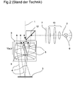
- a zoom, a tube with eyepieces and a built-in Illumination for an object field is carried out in the main beam path of the microscope usually between Main lens and zoom by means of a deflection element, for example a prism, see Fig. 2.
- the main objective is usually a high quality one, made up of several lens groups built-up optics that are becoming increasingly complex as they become increasingly higher Mapping services are required and a trend towards sliding There are lens groups for changing the focal length.
- the object of the invention is now a lens with lighting-in particular as the main lens for surgical microscopes - too create which from the point of view of high image quality and in particular a low overall height is the greatest possible Non-reflective in the observation beam path guaranteed.
- FIG. 1 shows the construction of a lens 8 with an inventive one Illumination incoupling.
- An optical axis 1 of the Objective 8 an illumination beam path 2, an object field 3, a Front lens group 9 of the lens 8, a lens part 10a for the Observation, a lens part 10b for lighting, a Deflection element 12 for lighting with a deflection surface 14 as well as entry and exit surfaces 15 and 16, an illumination optics 13, a light source 6 with reflector and stylized an aperture / display 7 shown.
- the light generated by the light source 6 is via the illumination optics 13 on the lens part 10b for lighting on the Deflection element 12, for example a mirror or a prism, guided.
- the deflection element 12 comprises a deflection surface 14, one Entry surface 15 and an exit surface 16. That of the deflecting element 12 redirected light is transmitted through the front lens group 9 of the objective 8 directed to the object field 3.
- the light reflected on the object field 3 becomes as an observation beam path 4 via the front lens group 9 of the Lens 8 guided to the lens part 10a for observation and from there on to the following optical, not shown Headed elements of the microscope such as zoom, tube and eyepiece.
- the illuminating beam path 2 is strict is guided separately from the observation beam path 4, so that unwanted reflections 5 from the illumination beam path 2 in the Observation beam path 4 can be avoided.
- the lens part 10b for lighting the separated lens part 10a for observation In order to will have the same image quality for both lighting and achieved for observation.
- 1a shows the division of the front lens group 9 into the front lens group parts 9a for the observation or 9b for the Lighting.
- FIG. 2 shows, analogously to FIG. 1, the structure of a conventional one Illumination incoupling.
- the lighting creates the different lens groups in the lens 8 reflections 5, which in the Observation beam path 4 and deteriorate.
- 3a to 3c show variants of the deflecting element 12 differently curved deflecting surface 14 or in and Exit surfaces 15 and 16.
- concave or convexly curved surfaces 14, 15, 16 become different optical properties (focal lengths) of the deflection element achieved.
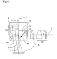
- FIG 4 shows a variant of the lighting coupling in accordance with the invention with a differently arranged deflection element 12 the front lens group part 9b for the illumination from the lens 8 removed and instead of this the deflecting element 12 on the same Level as the front lens group part 9a for observation used.
- the front lens group part 9b for lighting is to unchanged lighting optics like the one according to the invention reach into the illuminating beam path 2 outside the lens 8 used.
- FIG. 5 shows, by means of a cover 17, optically decoupled front lens group parts 9 and 9a.
- a cover 17 is between the front lens group part 9a for observation and the front lens group part 9b used for lighting.
- the objective 8 composed of several lens groups, whose part facing the object field 3 is the front lens group 9 of the Lens 8 forms, with the exception of this front lens group 9 in separate two parts of any shape.
- One part is for the Observation beam path 4, the other part for the illumination beam path 2 used.
- the objective part 10a for observation remains in its original place; the lens part 10b for the Illumination is removed from the original lens system and assigned to the light source 6 with reflector (lighting).
- the axis of this objective part 10b for the illumination is now there for example perpendicular to the optical axis 1 of the original undivided lens 8.
- a deflection element 12 - for example a prism or a mirror - in place used, on which the lens part 10b was previously for the lighting.
- the observation beam path 4 is thus also continued by the unchanged lens part 10a directed for observation.
- the Illumination beam path 2 is, according to the invention, directly above the Front lens group 9 coupled.
- the separated lens part 10b for the lighting although, for example, perpendicular to the optical axis 1 of the original lens 8 is arranged as before Image of the object field 3 used. This is due to the complex Structure of the lens part 10b separated for the lighting for the Illumination a correspondingly high correction of the illumination beam path 2 reached.
- the now increased air gap and the glass path in the deflecting element 12 in the Correction of the illumination beam path 2 should flow in, either in a changed correction of the lens part 10b for the lighting or in the choice of the additional lighting optics used 13th
- the illumination optics 13 can the invention additionally axially and radially movable panels and / or displays 7 can be installed.
- slidable Lens groups applied in the lens part 10b for lighting according to the design of the original lens 8.
- the application of the invention is not limited to stereomicroscopes, but can be used with simpler microscopes or also comparable devices with illumination through a lens be applied.
Landscapes
- Physics & Mathematics (AREA)
- Chemical & Material Sciences (AREA)
- Analytical Chemistry (AREA)
- General Physics & Mathematics (AREA)
- Optics & Photonics (AREA)
- Microscoopes, Condenser (AREA)
- Lenses (AREA)
Abstract
Description
- Fig.1:
- den Aufbau eines Objektivs mit einer erfindungsgemäßen Beleuchtungseinkoppelung;
- Fig.1a:
- die Aufteilung der Frontlinsengruppe des Objektivs in die Frontlinsengruppenteile für die Beobachtung beziehungsweise für die Beleuchtung;
- Fig.2:
- den Aufbau einer herkömmlichen Beleuchtungseinkoppelung oberhalb des Hauptobjektivs;
- Fig. 3a bis 3c:
- Varianten des Umlenkelements mit verschiedenartig gewölbter Umlenkfläche beziehungsweise Ein- und Austrittsflächen;
- Fig. 4:
- eine Variante der erfindungsgemäßen Beleuchtungseinkoppelung mit einem Umlenkelement, das in der Ebene der Frontlinsengruppe für die Beobachtung angeordnet ist, und
- Fig. 5:
- die mittels einer Abdeckung optisch entkoppelten Frontlinsengruppenteile.
- 1
- optische Achse von (8)
- 2
- Beleuchtungsstrahlengang
- 3
- Objektfeld
- 4
- Beobachtungsstrahlengang
- 5
- Reflexion(en) in (4)
- 6
- Lichtquelle mit Reflektor
- 7
- Blende/Display
- 8
- Objektiv
- 9
- Frontlinsengruppe von (8)
- 9a
- Frontlinsengruppenteil für die Beobachtung
- 9b
- Frontlinsengruppenteil für die Beleuchtung
- 10a
- Objektivteil für die Beobachtung
- 10b
- Objektivteil für die Beleuchtung
- 12
- Umlenkelement
- 13
- Beleuchtungsoptik
- 14
- Umlenkfläche von (12)
- 15
- Eintrittsfläche von (12)
- 16
- Austrittsfläche von (12)
- 17
- Abdeckung
Claims (10)
- Objektiv mit Beleuchtung - insbesondere für die Anwendung als Hauptobjektiv in einem Stereo-Operationsmikroskop mit einem mehrteiligen Objektiv (8), das in einen Objektivteil (10a) für die Beobachtung und einen zweiten Objektivteil (10b) für die Beleuchtung getrennt ist, dadurch gekennzeichnet, dass der Objektivteil (10a) für die Beleuchtung aus dem Objektiv (8) entfernt ist und in einem Winkel zur optischen Achse (1) des Objektivs (8) angeordnet ist.
- Objektiv nach Anspruch 1, dadurch gekennzeichnet, dass der Beleuchungsstrahlengang (2) mittels eines direkt über der Frontlinsengruppe (9) des Objektivs (8) angebrachten Umlenkelements (12) in den Strahlengang des Mikroskops eingekoppelt ist.
- Objektiv nach Anspruch 2, dadurch gekennzeichnet, dass wenigstens eine der Flächen: Umlenkfläche (14), Eintrittsfläche (15), Austrittsfläche (16) des Umlenkelements (12) gekrümmt beziehungsweise konvex oder konkav ausbildbar ist.
- Objektiv nach einem der vorhergehenden Ansprüche, dadurch gekennzeichnet, dass Abweichungen in der optischen Korrektion durch veränderte Luftabstände und/oder Glaswege des Umlenkelements (12) durch eine Veränderung des Objektivteils (10a) für die Beleuchtung und/oder durch die zusätzliche Beleuchtungsoptik (13) und/oder wenigstens eine gekrümmte Fläche (Umlenkfläche (14), Eintrittsfläche (15), Austrittsfläche (16) des Umlenkelements (12)) korrigiert sind.
- Objektiv nach einem der vorhergehenden Ansprüche, dadurch gekennzeichnet, dass in der optischen Achse (1) des Objektivs (8) verschiebbare optische Elemente im Objektivteil (10a) für die Beobachtung eine Lageveränderung der korrelierten optischen Elemente im Objektivteil (10b) für die Beleuchtung in der Achse des Beleuchtungsstrahlengangs (2) bewirken.
- Objektiv nach Anspruch 5, dadurch gekennzeichnet, dass die Koppelung der zum Beobachtungsstrahlengang (4) korrelierten optischen Elemente im Beleuchtungsstrahlengang (2) über eine mechanische und/oder elektromechanische und/oder elektronische Koppelung erfolgt.
- Objektiv nach einem der vorhergehenden Ansprüche, dadurch gekennzeichnet, dass die Frontlinsengruppe (9) des Objektivs (8) in zwei Frontlinsengruppenteile (9a) für die Beobachtung und (9b) für die Beleuchtung durchtrennt und optisch vom Beobachtungsstrahlengang (4) entkoppelt ist.
- Objektiv nach Anspruch 7, dadurch gekennzeichnet, dass die Entkoppelung eine Abdeckung (17) umfasst.
- Objektiv nach Anspruch 7 oder 8, dadurch gekennzeichnet, dass der Frontlinsengruppenteil (9b) für die Beleuchtung dem Objektivteil (10b) für die Beleuchtung zugeordnet ist und das Umlenkelement (12) in einer Ebene mit dem Frontlinsengruppenteil (9a) für die Beobachtung angeordnet ist.
- Objektiv nach einem der vorhergehenden Ansprüche, dadurch gekennzeichnet, dass die Trennung des Objektivs (8) in einen Objektivteil (10a) für die Beobachtung und einen Objektivteil (10b) für die Beleuchtung in einer von der Halbierung abweichenden Form erfolgt.
Applications Claiming Priority (2)
| Application Number | Priority Date | Filing Date | Title |
|---|---|---|---|
| DE10235706 | 2002-08-03 | ||
| DE10235706A DE10235706A1 (de) | 2002-08-03 | 2002-08-03 | Objektiv mit Beleuchtung |
Publications (2)
| Publication Number | Publication Date |
|---|---|
| EP1387202A2 true EP1387202A2 (de) | 2004-02-04 |
| EP1387202A3 EP1387202A3 (de) | 2004-03-10 |
Family
ID=30010597
Family Applications (1)
| Application Number | Title | Priority Date | Filing Date |
|---|---|---|---|
| EP03015848A Withdrawn EP1387202A3 (de) | 2002-08-03 | 2003-07-11 | Objektiv mit Beleuchtung |
Country Status (4)
| Country | Link |
|---|---|
| US (1) | US20040021937A1 (de) |
| EP (1) | EP1387202A3 (de) |
| JP (1) | JP4414696B2 (de) |
| DE (1) | DE10235706A1 (de) |
Families Citing this family (5)
| Publication number | Priority date | Publication date | Assignee | Title |
|---|---|---|---|---|
| DE102007029893A1 (de) * | 2007-06-28 | 2009-01-15 | Leica Microsystems (Schweiz) Ag | Mikroskop mit zentrierter Beleuchtung |
| DE102007029896B3 (de) * | 2007-06-28 | 2008-06-26 | Leica Microsystems (Schweiz) Ag | Mikroskop mit zentrierter Beleuchtung |
| JP5188927B2 (ja) * | 2008-10-24 | 2013-04-24 | オリンパスメディカルシステムズ株式会社 | 照明光学系 |
| JP6448933B2 (ja) * | 2014-07-09 | 2019-01-09 | 日本板硝子株式会社 | 蛍光検出用光学装置 |
| JP6664462B2 (ja) * | 2018-12-05 | 2020-03-13 | 日本板硝子株式会社 | 蛍光検出用光学装置 |
Citations (7)
| Publication number | Priority date | Publication date | Assignee | Title |
|---|---|---|---|---|
| DE2932486A1 (de) | 1979-08-10 | 1981-02-26 | Moeller J D Optik | Operationsmikroskop |
| DE3427592A1 (de) | 1984-07-26 | 1986-02-06 | Fa. Carl Zeiss, 7920 Heidenheim | Koaxiales beleuchtungssystem fuer operationsmikroskope |
| DE19523712A1 (de) | 1994-06-23 | 1996-01-04 | Topcon Corp | Stereomikroskop |
| DE19830596A1 (de) * | 1997-07-10 | 1999-01-14 | Univ Ruprecht Karls Heidelberg | Wellenfeldmikroskop, Wellenfeldmikroskopieverfahren, auch zur DNA-Sequenzierung, und Kalibrierverfahren für die Wellenfeldmikroskopie |
| DE19739428A1 (de) | 1997-09-09 | 1999-03-11 | Zeiss Carl Fa | Beleuchtungseinrichtung für ein Operationsmikroskop |
| JP2000039567A (ja) * | 1998-07-23 | 2000-02-08 | Nikon Corp | 双眼顕微鏡と双眼顕微鏡による撮像方法 |
| US6392797B2 (en) | 2000-05-31 | 2002-05-21 | Carl-Zeiss-Stiftung | Viewing apparatus |
Family Cites Families (4)
| Publication number | Priority date | Publication date | Assignee | Title |
|---|---|---|---|---|
| DE3623613A1 (de) * | 1986-07-12 | 1988-01-21 | Zeiss Carl Fa | Koaxiales beleuchtungssystem fuer operationsmikroskope |
| JPH0757226B2 (ja) * | 1986-10-27 | 1995-06-21 | オリンパス光学工業株式会社 | 手術用顕微鏡 |
| JP2891923B2 (ja) * | 1996-03-01 | 1999-05-17 | 三鷹光器株式会社 | 顕微鏡の照明構造 |
| DE59902878D1 (de) * | 1999-12-15 | 2002-10-31 | Moeller Wedel Gmbh | Beleuchtungseinrichtung für ein Operationsmikroskop |
-
2002
- 2002-08-03 DE DE10235706A patent/DE10235706A1/de not_active Withdrawn
-
2003
- 2003-07-11 EP EP03015848A patent/EP1387202A3/de not_active Withdrawn
- 2003-07-28 US US10/628,671 patent/US20040021937A1/en not_active Abandoned
- 2003-08-04 JP JP2003286071A patent/JP4414696B2/ja not_active Expired - Lifetime
Patent Citations (7)
| Publication number | Priority date | Publication date | Assignee | Title |
|---|---|---|---|---|
| DE2932486A1 (de) | 1979-08-10 | 1981-02-26 | Moeller J D Optik | Operationsmikroskop |
| DE3427592A1 (de) | 1984-07-26 | 1986-02-06 | Fa. Carl Zeiss, 7920 Heidenheim | Koaxiales beleuchtungssystem fuer operationsmikroskope |
| DE19523712A1 (de) | 1994-06-23 | 1996-01-04 | Topcon Corp | Stereomikroskop |
| DE19830596A1 (de) * | 1997-07-10 | 1999-01-14 | Univ Ruprecht Karls Heidelberg | Wellenfeldmikroskop, Wellenfeldmikroskopieverfahren, auch zur DNA-Sequenzierung, und Kalibrierverfahren für die Wellenfeldmikroskopie |
| DE19739428A1 (de) | 1997-09-09 | 1999-03-11 | Zeiss Carl Fa | Beleuchtungseinrichtung für ein Operationsmikroskop |
| JP2000039567A (ja) * | 1998-07-23 | 2000-02-08 | Nikon Corp | 双眼顕微鏡と双眼顕微鏡による撮像方法 |
| US6392797B2 (en) | 2000-05-31 | 2002-05-21 | Carl-Zeiss-Stiftung | Viewing apparatus |
Also Published As
| Publication number | Publication date |
|---|---|
| JP2004070357A (ja) | 2004-03-04 |
| EP1387202A3 (de) | 2004-03-10 |
| US20040021937A1 (en) | 2004-02-05 |
| JP4414696B2 (ja) | 2010-02-10 |
| DE10235706A1 (de) | 2004-02-19 |
Similar Documents
| Publication | Publication Date | Title |
|---|---|---|
| DE102014108811B3 (de) | Stereomikroskop mit einem Hauptbeobachterstrahlengang und einem Mitbeobachterstrahlengang | |
| DE102006046555A1 (de) | Miniaturisiertes optisch abbildendes System mit hoher lateraler und axialer Auflösung | |
| DE10229935A1 (de) | Einrichtung zur Einkopplung von Licht in ein Mikroskop | |
| DE3938412A1 (de) | Mikroskop mit einem diagonal verlaufenden beobachtungsstrahlengang | |
| DE102007029893A1 (de) | Mikroskop mit zentrierter Beleuchtung | |
| EP1067420B1 (de) | DUV-taugliches Mikroskop-Objektiv mit parfokalem IR-Fokus | |
| EP0019263B2 (de) | Mikroskopoptiksystem | |
| EP2648028B1 (de) | Varioskopoptik und Mikroskop mit einer Varioskopoptik | |
| WO2005045501A1 (de) | Invertierbares lichtmikroskop | |
| DE102007029896B3 (de) | Mikroskop mit zentrierter Beleuchtung | |
| WO2004051343A1 (de) | Vorrichtung zur ausspiegelung eines stereoskopischen beobachtungsstrahlengangs | |
| DE3318011C2 (de) | Zusatzeinrichtung für Stereomikroskope | |
| DE102006012388A1 (de) | Mikroskopiesystem | |
| EP1460466A1 (de) | Mikroskop, insbesondere Stereomikroskop | |
| EP1387202A2 (de) | Objektiv mit Beleuchtung | |
| EP1019770B1 (de) | Mikroskop mit auflichteinkopplung | |
| DE2407270C2 (de) | Vergleichsmikroskop | |
| EP1341024B1 (de) | Beleuchtungseinkoppelung für eine optische Betrachtungseinrichtung | |
| DE102010018123A1 (de) | Optisches System zur Beeinflussung der Richtung oder der Farbeigenschaften eines Abbildungsstrahlengangs | |
| DE102006022592B4 (de) | Mikroskop mit Beleuchtungseinheit | |
| DE102007029894A1 (de) | Mikroskop mit zentrierter Beleuchtung | |
| DE102014108596B3 (de) | Objektiv und optisches Gerät | |
| DE102006022590C5 (de) | Beleuchtungseinheit für ein Mikroskop | |
| DE102005050171B4 (de) | Optisches Vergrösserungsänderungssystem zur Bereitstellung von optischen Abbildungsvergrösserungen und Mikroskop mit einem solchen | |
| DE3205305A1 (de) | Uebersichtsobjektiv |
Legal Events
| Date | Code | Title | Description |
|---|---|---|---|
| PUAI | Public reference made under article 153(3) epc to a published international application that has entered the european phase |
Free format text: ORIGINAL CODE: 0009012 |
|
| PUAL | Search report despatched |
Free format text: ORIGINAL CODE: 0009013 |
|
| AK | Designated contracting states |
Kind code of ref document: A2 Designated state(s): AT BE BG CH CY CZ DE DK EE ES FI FR GB GR HU IE IT LI LU MC NL PT RO SE SI SK TR |
|
| AX | Request for extension of the european patent |
Extension state: AL LT LV MK |
|
| AK | Designated contracting states |
Kind code of ref document: A3 Designated state(s): AT BE BG CH CY CZ DE DK EE ES FI FR GB GR HU IE IT LI LU MC NL PT RO SE SI SK TR |
|
| AX | Request for extension of the european patent |
Extension state: AL LT LV MK |
|
| RIC1 | Information provided on ipc code assigned before grant |
Ipc: 7G 02B 21/06 A Ipc: 7G 02B 21/08 B |
|
| 17P | Request for examination filed |
Effective date: 20040907 |
|
| AKX | Designation fees paid |
Designated state(s): DE FR GB |
|
| 17Q | First examination report despatched |
Effective date: 20050125 |
|
| RAP1 | Party data changed (applicant data changed or rights of an application transferred) |
Owner name: LEICA INSTRUMENTS PTE. LTD. |
|
| RAP1 | Party data changed (applicant data changed or rights of an application transferred) |
Owner name: LEICA INSTRUMENTS (SINGAPORE) PTE. LTD. |
|
| STAA | Information on the status of an ep patent application or granted ep patent |
Free format text: STATUS: THE APPLICATION IS DEEMED TO BE WITHDRAWN |
|
| 18D | Application deemed to be withdrawn |
Effective date: 20171214 |
|
| RIC1 | Information provided on ipc code assigned before grant |
Ipc: G02B 21/06 20060101AFI20031009BHEP Ipc: G02B 21/08 20060101ALI20040121BHEP |