EP1387202A2 - Objectif avec dispositif d'illumination - Google Patents
Objectif avec dispositif d'illumination Download PDFInfo
- Publication number
- EP1387202A2 EP1387202A2 EP03015848A EP03015848A EP1387202A2 EP 1387202 A2 EP1387202 A2 EP 1387202A2 EP 03015848 A EP03015848 A EP 03015848A EP 03015848 A EP03015848 A EP 03015848A EP 1387202 A2 EP1387202 A2 EP 1387202A2
- Authority
- EP
- European Patent Office
- Prior art keywords
- objective
- illumination
- observation
- lens
- beam path
- Prior art date
- Legal status (The legal status is an assumption and is not a legal conclusion. Google has not performed a legal analysis and makes no representation as to the accuracy of the status listed.)
- Withdrawn
Links
- 238000005286 illumination Methods 0.000 title claims abstract description 43
- 230000003287 optical effect Effects 0.000 claims abstract description 20
- 230000008878 coupling Effects 0.000 claims description 7
- 238000010168 coupling process Methods 0.000 claims description 7
- 238000005859 coupling reaction Methods 0.000 claims description 7
- 238000012937 correction Methods 0.000 claims description 4
- 239000011521 glass Substances 0.000 claims description 2
- 230000002596 correlated effect Effects 0.000 claims 2
- 230000000694 effects Effects 0.000 claims 1
- 238000000926 separation method Methods 0.000 claims 1
- 238000010276 construction Methods 0.000 description 3
- 238000011161 development Methods 0.000 description 2
- 238000012634 optical imaging Methods 0.000 description 2
- 206010052128 Glare Diseases 0.000 description 1
- 238000013459 approach Methods 0.000 description 1
- 230000001419 dependent effect Effects 0.000 description 1
- 238000013461 design Methods 0.000 description 1
- 230000006866 deterioration Effects 0.000 description 1
- 238000013507 mapping Methods 0.000 description 1
- 238000000034 method Methods 0.000 description 1
- 239000000243 solution Substances 0.000 description 1
- 239000012086 standard solution Substances 0.000 description 1
Images


Classifications
-
- G—PHYSICS
- G02—OPTICS
- G02B—OPTICAL ELEMENTS, SYSTEMS OR APPARATUS
- G02B21/00—Microscopes
- G02B21/06—Means for illuminating specimens
- G02B21/08—Condensers
- G02B21/082—Condensers for incident illumination only
Definitions
- the invention relates to a lens with lighting, in particular for Use as the main objective in a stereo surgical microscope or with other optical instruments.
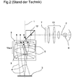
- a zoom, a tube with eyepieces and a built-in Illumination for an object field is carried out in the main beam path of the microscope usually between Main lens and zoom by means of a deflection element, for example a prism, see Fig. 2.
- the main objective is usually a high quality one, made up of several lens groups built-up optics that are becoming increasingly complex as they become increasingly higher Mapping services are required and a trend towards sliding There are lens groups for changing the focal length.
- the object of the invention is now a lens with lighting-in particular as the main lens for surgical microscopes - too create which from the point of view of high image quality and in particular a low overall height is the greatest possible Non-reflective in the observation beam path guaranteed.
- FIG. 1 shows the construction of a lens 8 with an inventive one Illumination incoupling.
- An optical axis 1 of the Objective 8 an illumination beam path 2, an object field 3, a Front lens group 9 of the lens 8, a lens part 10a for the Observation, a lens part 10b for lighting, a Deflection element 12 for lighting with a deflection surface 14 as well as entry and exit surfaces 15 and 16, an illumination optics 13, a light source 6 with reflector and stylized an aperture / display 7 shown.
- the light generated by the light source 6 is via the illumination optics 13 on the lens part 10b for lighting on the Deflection element 12, for example a mirror or a prism, guided.
- the deflection element 12 comprises a deflection surface 14, one Entry surface 15 and an exit surface 16. That of the deflecting element 12 redirected light is transmitted through the front lens group 9 of the objective 8 directed to the object field 3.
- the light reflected on the object field 3 becomes as an observation beam path 4 via the front lens group 9 of the Lens 8 guided to the lens part 10a for observation and from there on to the following optical, not shown Headed elements of the microscope such as zoom, tube and eyepiece.
- the illuminating beam path 2 is strict is guided separately from the observation beam path 4, so that unwanted reflections 5 from the illumination beam path 2 in the Observation beam path 4 can be avoided.
- the lens part 10b for lighting the separated lens part 10a for observation In order to will have the same image quality for both lighting and achieved for observation.
- 1a shows the division of the front lens group 9 into the front lens group parts 9a for the observation or 9b for the Lighting.
- FIG. 2 shows, analogously to FIG. 1, the structure of a conventional one Illumination incoupling.
- the lighting creates the different lens groups in the lens 8 reflections 5, which in the Observation beam path 4 and deteriorate.
- 3a to 3c show variants of the deflecting element 12 differently curved deflecting surface 14 or in and Exit surfaces 15 and 16.
- concave or convexly curved surfaces 14, 15, 16 become different optical properties (focal lengths) of the deflection element achieved.
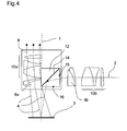
- FIG 4 shows a variant of the lighting coupling in accordance with the invention with a differently arranged deflection element 12 the front lens group part 9b for the illumination from the lens 8 removed and instead of this the deflecting element 12 on the same Level as the front lens group part 9a for observation used.
- the front lens group part 9b for lighting is to unchanged lighting optics like the one according to the invention reach into the illuminating beam path 2 outside the lens 8 used.
- FIG. 5 shows, by means of a cover 17, optically decoupled front lens group parts 9 and 9a.
- a cover 17 is between the front lens group part 9a for observation and the front lens group part 9b used for lighting.
- the objective 8 composed of several lens groups, whose part facing the object field 3 is the front lens group 9 of the Lens 8 forms, with the exception of this front lens group 9 in separate two parts of any shape.
- One part is for the Observation beam path 4, the other part for the illumination beam path 2 used.
- the objective part 10a for observation remains in its original place; the lens part 10b for the Illumination is removed from the original lens system and assigned to the light source 6 with reflector (lighting).
- the axis of this objective part 10b for the illumination is now there for example perpendicular to the optical axis 1 of the original undivided lens 8.
- a deflection element 12 - for example a prism or a mirror - in place used, on which the lens part 10b was previously for the lighting.
- the observation beam path 4 is thus also continued by the unchanged lens part 10a directed for observation.
- the Illumination beam path 2 is, according to the invention, directly above the Front lens group 9 coupled.
- the separated lens part 10b for the lighting although, for example, perpendicular to the optical axis 1 of the original lens 8 is arranged as before Image of the object field 3 used. This is due to the complex Structure of the lens part 10b separated for the lighting for the Illumination a correspondingly high correction of the illumination beam path 2 reached.
- the now increased air gap and the glass path in the deflecting element 12 in the Correction of the illumination beam path 2 should flow in, either in a changed correction of the lens part 10b for the lighting or in the choice of the additional lighting optics used 13th
- the illumination optics 13 can the invention additionally axially and radially movable panels and / or displays 7 can be installed.
- slidable Lens groups applied in the lens part 10b for lighting according to the design of the original lens 8.
- the application of the invention is not limited to stereomicroscopes, but can be used with simpler microscopes or also comparable devices with illumination through a lens be applied.
Landscapes
- Physics & Mathematics (AREA)
- Chemical & Material Sciences (AREA)
- Analytical Chemistry (AREA)
- General Physics & Mathematics (AREA)
- Optics & Photonics (AREA)
- Microscoopes, Condenser (AREA)
- Lenses (AREA)
Applications Claiming Priority (2)
| Application Number | Priority Date | Filing Date | Title |
|---|---|---|---|
| DE10235706 | 2002-08-03 | ||
| DE10235706A DE10235706A1 (de) | 2002-08-03 | 2002-08-03 | Objektiv mit Beleuchtung |
Publications (2)
| Publication Number | Publication Date |
|---|---|
| EP1387202A2 true EP1387202A2 (fr) | 2004-02-04 |
| EP1387202A3 EP1387202A3 (fr) | 2004-03-10 |
Family
ID=30010597
Family Applications (1)
| Application Number | Title | Priority Date | Filing Date |
|---|---|---|---|
| EP03015848A Withdrawn EP1387202A3 (fr) | 2002-08-03 | 2003-07-11 | Objectif avec dispositif d'illumination |
Country Status (4)
| Country | Link |
|---|---|
| US (1) | US20040021937A1 (fr) |
| EP (1) | EP1387202A3 (fr) |
| JP (1) | JP4414696B2 (fr) |
| DE (1) | DE10235706A1 (fr) |
Families Citing this family (5)
| Publication number | Priority date | Publication date | Assignee | Title |
|---|---|---|---|---|
| DE102007029893A1 (de) * | 2007-06-28 | 2009-01-15 | Leica Microsystems (Schweiz) Ag | Mikroskop mit zentrierter Beleuchtung |
| DE102007029896B3 (de) * | 2007-06-28 | 2008-06-26 | Leica Microsystems (Schweiz) Ag | Mikroskop mit zentrierter Beleuchtung |
| JP5188927B2 (ja) * | 2008-10-24 | 2013-04-24 | オリンパスメディカルシステムズ株式会社 | 照明光学系 |
| JP6448933B2 (ja) * | 2014-07-09 | 2019-01-09 | 日本板硝子株式会社 | 蛍光検出用光学装置 |
| JP6664462B2 (ja) * | 2018-12-05 | 2020-03-13 | 日本板硝子株式会社 | 蛍光検出用光学装置 |
Citations (7)
| Publication number | Priority date | Publication date | Assignee | Title |
|---|---|---|---|---|
| DE2932486A1 (de) | 1979-08-10 | 1981-02-26 | Moeller J D Optik | Operationsmikroskop |
| DE3427592A1 (de) | 1984-07-26 | 1986-02-06 | Fa. Carl Zeiss, 7920 Heidenheim | Koaxiales beleuchtungssystem fuer operationsmikroskope |
| DE19523712A1 (de) | 1994-06-23 | 1996-01-04 | Topcon Corp | Stereomikroskop |
| DE19830596A1 (de) * | 1997-07-10 | 1999-01-14 | Univ Ruprecht Karls Heidelberg | Wellenfeldmikroskop, Wellenfeldmikroskopieverfahren, auch zur DNA-Sequenzierung, und Kalibrierverfahren für die Wellenfeldmikroskopie |
| DE19739428A1 (de) | 1997-09-09 | 1999-03-11 | Zeiss Carl Fa | Beleuchtungseinrichtung für ein Operationsmikroskop |
| JP2000039567A (ja) * | 1998-07-23 | 2000-02-08 | Nikon Corp | 双眼顕微鏡と双眼顕微鏡による撮像方法 |
| US6392797B2 (en) | 2000-05-31 | 2002-05-21 | Carl-Zeiss-Stiftung | Viewing apparatus |
Family Cites Families (4)
| Publication number | Priority date | Publication date | Assignee | Title |
|---|---|---|---|---|
| DE3623613A1 (de) * | 1986-07-12 | 1988-01-21 | Zeiss Carl Fa | Koaxiales beleuchtungssystem fuer operationsmikroskope |
| JPH0757226B2 (ja) * | 1986-10-27 | 1995-06-21 | オリンパス光学工業株式会社 | 手術用顕微鏡 |
| JP2891923B2 (ja) * | 1996-03-01 | 1999-05-17 | 三鷹光器株式会社 | 顕微鏡の照明構造 |
| DE59902878D1 (de) * | 1999-12-15 | 2002-10-31 | Moeller Wedel Gmbh | Beleuchtungseinrichtung für ein Operationsmikroskop |
-
2002
- 2002-08-03 DE DE10235706A patent/DE10235706A1/de not_active Withdrawn
-
2003
- 2003-07-11 EP EP03015848A patent/EP1387202A3/fr not_active Withdrawn
- 2003-07-28 US US10/628,671 patent/US20040021937A1/en not_active Abandoned
- 2003-08-04 JP JP2003286071A patent/JP4414696B2/ja not_active Expired - Lifetime
Patent Citations (7)
| Publication number | Priority date | Publication date | Assignee | Title |
|---|---|---|---|---|
| DE2932486A1 (de) | 1979-08-10 | 1981-02-26 | Moeller J D Optik | Operationsmikroskop |
| DE3427592A1 (de) | 1984-07-26 | 1986-02-06 | Fa. Carl Zeiss, 7920 Heidenheim | Koaxiales beleuchtungssystem fuer operationsmikroskope |
| DE19523712A1 (de) | 1994-06-23 | 1996-01-04 | Topcon Corp | Stereomikroskop |
| DE19830596A1 (de) * | 1997-07-10 | 1999-01-14 | Univ Ruprecht Karls Heidelberg | Wellenfeldmikroskop, Wellenfeldmikroskopieverfahren, auch zur DNA-Sequenzierung, und Kalibrierverfahren für die Wellenfeldmikroskopie |
| DE19739428A1 (de) | 1997-09-09 | 1999-03-11 | Zeiss Carl Fa | Beleuchtungseinrichtung für ein Operationsmikroskop |
| JP2000039567A (ja) * | 1998-07-23 | 2000-02-08 | Nikon Corp | 双眼顕微鏡と双眼顕微鏡による撮像方法 |
| US6392797B2 (en) | 2000-05-31 | 2002-05-21 | Carl-Zeiss-Stiftung | Viewing apparatus |
Also Published As
| Publication number | Publication date |
|---|---|
| JP2004070357A (ja) | 2004-03-04 |
| EP1387202A3 (fr) | 2004-03-10 |
| US20040021937A1 (en) | 2004-02-05 |
| JP4414696B2 (ja) | 2010-02-10 |
| DE10235706A1 (de) | 2004-02-19 |
Similar Documents
| Publication | Publication Date | Title |
|---|---|---|
| DE102014108811B3 (de) | Stereomikroskop mit einem Hauptbeobachterstrahlengang und einem Mitbeobachterstrahlengang | |
| DE102006046555A1 (de) | Miniaturisiertes optisch abbildendes System mit hoher lateraler und axialer Auflösung | |
| DE10229935A1 (de) | Einrichtung zur Einkopplung von Licht in ein Mikroskop | |
| DE3938412A1 (de) | Mikroskop mit einem diagonal verlaufenden beobachtungsstrahlengang | |
| DE102007029893A1 (de) | Mikroskop mit zentrierter Beleuchtung | |
| EP1067420B1 (fr) | Objectif de microscope pour l'ultraviolet profond, à mise au point pour l'infrarouge parfocale | |
| EP0019263B2 (fr) | Système optique pour microscopes | |
| EP2648028B1 (fr) | Optique de varioscope et microscope doté d'un optique de varioscope | |
| WO2005045501A1 (fr) | Microscope optique inversible | |
| DE102007029896B3 (de) | Mikroskop mit zentrierter Beleuchtung | |
| WO2004051343A1 (fr) | Dispositif de reflexion d'une trajectoire de faisceau d'observation stereoscopique | |
| DE3318011C2 (de) | Zusatzeinrichtung für Stereomikroskope | |
| DE102006012388A1 (de) | Mikroskopiesystem | |
| EP1460466A1 (fr) | Microsocope, notamment microscope stéréoscopique | |
| EP1387202A2 (fr) | Objectif avec dispositif d'illumination | |
| EP1019770B1 (fr) | Microscope a injection de lumiere incidente | |
| DE2407270C2 (de) | Vergleichsmikroskop | |
| EP1341024B1 (fr) | Dispositif d'éclairage pour système optique d'observation | |
| DE102010018123A1 (de) | Optisches System zur Beeinflussung der Richtung oder der Farbeigenschaften eines Abbildungsstrahlengangs | |
| DE102006022592B4 (de) | Mikroskop mit Beleuchtungseinheit | |
| DE102007029894A1 (de) | Mikroskop mit zentrierter Beleuchtung | |
| DE102014108596B3 (de) | Objektiv und optisches Gerät | |
| DE102006022590C5 (de) | Beleuchtungseinheit für ein Mikroskop | |
| DE102005050171B4 (de) | Optisches Vergrösserungsänderungssystem zur Bereitstellung von optischen Abbildungsvergrösserungen und Mikroskop mit einem solchen | |
| DE3205305A1 (de) | Uebersichtsobjektiv |
Legal Events
| Date | Code | Title | Description |
|---|---|---|---|
| PUAI | Public reference made under article 153(3) epc to a published international application that has entered the european phase |
Free format text: ORIGINAL CODE: 0009012 |
|
| PUAL | Search report despatched |
Free format text: ORIGINAL CODE: 0009013 |
|
| AK | Designated contracting states |
Kind code of ref document: A2 Designated state(s): AT BE BG CH CY CZ DE DK EE ES FI FR GB GR HU IE IT LI LU MC NL PT RO SE SI SK TR |
|
| AX | Request for extension of the european patent |
Extension state: AL LT LV MK |
|
| AK | Designated contracting states |
Kind code of ref document: A3 Designated state(s): AT BE BG CH CY CZ DE DK EE ES FI FR GB GR HU IE IT LI LU MC NL PT RO SE SI SK TR |
|
| AX | Request for extension of the european patent |
Extension state: AL LT LV MK |
|
| RIC1 | Information provided on ipc code assigned before grant |
Ipc: 7G 02B 21/06 A Ipc: 7G 02B 21/08 B |
|
| 17P | Request for examination filed |
Effective date: 20040907 |
|
| AKX | Designation fees paid |
Designated state(s): DE FR GB |
|
| 17Q | First examination report despatched |
Effective date: 20050125 |
|
| RAP1 | Party data changed (applicant data changed or rights of an application transferred) |
Owner name: LEICA INSTRUMENTS PTE. LTD. |
|
| RAP1 | Party data changed (applicant data changed or rights of an application transferred) |
Owner name: LEICA INSTRUMENTS (SINGAPORE) PTE. LTD. |
|
| STAA | Information on the status of an ep patent application or granted ep patent |
Free format text: STATUS: THE APPLICATION IS DEEMED TO BE WITHDRAWN |
|
| 18D | Application deemed to be withdrawn |
Effective date: 20171214 |
|
| RIC1 | Information provided on ipc code assigned before grant |
Ipc: G02B 21/06 20060101AFI20031009BHEP Ipc: G02B 21/08 20060101ALI20040121BHEP |