EP1387355B1 - Vorrichtung zum Antrieb einer Objektivlinse in einem optischen Kopf - Google Patents
Vorrichtung zum Antrieb einer Objektivlinse in einem optischen Kopf Download PDFInfo
- Publication number
- EP1387355B1 EP1387355B1 EP03253670A EP03253670A EP1387355B1 EP 1387355 B1 EP1387355 B1 EP 1387355B1 EP 03253670 A EP03253670 A EP 03253670A EP 03253670 A EP03253670 A EP 03253670A EP 1387355 B1 EP1387355 B1 EP 1387355B1
- Authority
- EP
- European Patent Office
- Prior art keywords
- blade
- objective lens
- wires
- driving apparatus
- lens driving
- Prior art date
- Legal status (The legal status is an assumption and is not a legal conclusion. Google has not performed a legal analysis and makes no representation as to the accuracy of the status listed.)
- Expired - Lifetime
Links
Images




Classifications
-
- G—PHYSICS
- G11—INFORMATION STORAGE
- G11B—INFORMATION STORAGE BASED ON RELATIVE MOVEMENT BETWEEN RECORD CARRIER AND TRANSDUCER
- G11B7/00—Recording or reproducing by optical means, e.g. recording using a thermal beam of optical radiation by modifying optical properties or the physical structure, reproducing using an optical beam at lower power by sensing optical properties; Record carriers therefor
- G11B7/08—Disposition or mounting of heads or light sources relatively to record carriers
- G11B7/09—Disposition or mounting of heads or light sources relatively to record carriers with provision for moving the light beam or focus plane for the purpose of maintaining alignment of the light beam relative to the record carrier during transducing operation, e.g. to compensate for surface irregularities of the latter or for track following
- G11B7/095—Disposition or mounting of heads or light sources relatively to record carriers with provision for moving the light beam or focus plane for the purpose of maintaining alignment of the light beam relative to the record carrier during transducing operation, e.g. to compensate for surface irregularities of the latter or for track following specially adapted for discs, e.g. for compensation of eccentricity or wobble
- G11B7/0956—Disposition or mounting of heads or light sources relatively to record carriers with provision for moving the light beam or focus plane for the purpose of maintaining alignment of the light beam relative to the record carrier during transducing operation, e.g. to compensate for surface irregularities of the latter or for track following specially adapted for discs, e.g. for compensation of eccentricity or wobble to compensate for tilt, skew, warp or inclination of the disc, i.e. maintain the optical axis at right angles to the disc
-
- G—PHYSICS
- G11—INFORMATION STORAGE
- G11B—INFORMATION STORAGE BASED ON RELATIVE MOVEMENT BETWEEN RECORD CARRIER AND TRANSDUCER
- G11B7/00—Recording or reproducing by optical means, e.g. recording using a thermal beam of optical radiation by modifying optical properties or the physical structure, reproducing using an optical beam at lower power by sensing optical properties; Record carriers therefor
- G11B7/08—Disposition or mounting of heads or light sources relatively to record carriers
- G11B7/09—Disposition or mounting of heads or light sources relatively to record carriers with provision for moving the light beam or focus plane for the purpose of maintaining alignment of the light beam relative to the record carrier during transducing operation, e.g. to compensate for surface irregularities of the latter or for track following
- G11B7/0925—Electromechanical actuators for lens positioning
- G11B7/0932—Details of sprung supports
-
- G—PHYSICS
- G11—INFORMATION STORAGE
- G11B—INFORMATION STORAGE BASED ON RELATIVE MOVEMENT BETWEEN RECORD CARRIER AND TRANSDUCER
- G11B7/00—Recording or reproducing by optical means, e.g. recording using a thermal beam of optical radiation by modifying optical properties or the physical structure, reproducing using an optical beam at lower power by sensing optical properties; Record carriers therefor
- G11B7/08—Disposition or mounting of heads or light sources relatively to record carriers
- G11B7/09—Disposition or mounting of heads or light sources relatively to record carriers with provision for moving the light beam or focus plane for the purpose of maintaining alignment of the light beam relative to the record carrier during transducing operation, e.g. to compensate for surface irregularities of the latter or for track following
- G11B7/0946—Disposition or mounting of heads or light sources relatively to record carriers with provision for moving the light beam or focus plane for the purpose of maintaining alignment of the light beam relative to the record carrier during transducing operation, e.g. to compensate for surface irregularities of the latter or for track following specially adapted for operation during external perturbations not related to the carrier or servo beam, e.g. vibration
Definitions
- the present invention relates to an objective lens driving apparatus for an optical pickup, and more particularly, to an objective lens driving apparatus for an optical pickup having an improved arrangement structure including an elastic support member supporting a blade on which an objective lens is mounted to be capable of elastically moving.
- optical pickups record or reproduce information on or from a disk, a recording medium, by emitting light thereon.
- the light emitted from the optical pickup must be perpendicularly incident on a recording surface of a disk to form a light spot of an accurate focus. If a light incident direction is inclined, an accurate light spot cannot be formed on the disk so that an error may occur during recording and reproduction of data.
- the light must be perpendicularly incident on the recording surface of the disk.
- the adjustment of the light to be perpendicularly incident on the recording surface of the disk is referred to a tilt adjustment or skew adjustment.
- an optical pickup apparatus includes a servo mechanism controlling the position of the objective lens in a focusing direction and a tracking direction so that the focus of light can be accurately formed on a desired track of a recording surface of a disk.
- the servo mechanism controls the focus of a light spot by maintaining a predetermined distance between the objective lens and the recording surface of the disk and the light spot to trace a desired track, it does not directly control the incident angle between the light and the recording surface of the disk.
- a function to dynamically control the tilt is needed.
- the optical pickup is a servo mechanism to control the position of an objective lens 1 and includes a focus control mechanism driving a blade 2 where the objective lens 1 is mounted in a focus direction A, a tracking control mechanism driving the blade 2 in a tracking direction B, and a tilt control mechanism driving the blade 2 in a tilt direction C.
- the focus and tracking control mechanisms are formed by a pair of focus coils 3a and 3b, a tracking coil 4, and a magnet 6.
- an electromagnetic force driving the blade 2 in a corresponding direction is generated by applying current to the focus coils 3a and 3b and the tracking coil 4.
- the tilt control mechanism typically is formed separate from the focus and tracking control mechanisms.
- the tilt control mechanism is formed to be commonly used as the focus control mechanism. That is, during tilt control, an electromagnetic force to drive the blade 2 in the tilt direction C is generated by applying current in a different way from the current applied during control to the focus coils 3a and 3b symmetrically arranged to the left and right.
- currents are identically applied to the left and right focus coils 3a and 3b to drive the blade 2 in the focus direction A.
- currents are applied in different directions to the left and right focus coils 3a and 3b to drive the blade 2 in the tilt direction C.
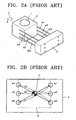
- FIG. 2A shows the structure of Figure 1 in a simple form for the convenience of explanation.
- Figure 2B three pairs of wires W1 and W6, W2 and W5, and W3 and W4 are arranged to face each other with respect to a point P which is the center of rotation when the blade 2 is tilt driven.
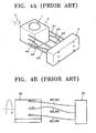
- the amounts of deformation of the third, fourth, and sixth wires W3, W4, and W6 are the same as that of the first wire W1 while the amount of deformation of the fifth wire W5 is the same as that of the second wire W2. That is, the first, third, fourth, and sixth wires W1, W3, W4, and W6 are bent to a relatively greater degree while the second and fifth wires W2 and W5 are bent to a relatively smaller degree. Then, a compression force acts on the second and fifth wires W2 and W5 so that the second and fifth wires W2 and W5 are buckled as shown in Figures 4A and 4B.
- US5 905 255 discloses a lens driving apparatus including four wire members that support the movable memory in the focusing, tracking and tilt direction.
- US 2002/0071376 discloses a lens driving device including wire supports that permit movement in the focusing, tracking and inclining direction of an optical axis.
- the present invention provides an objective lens driving apparatus of an optical pickup having an improved structure to support the blade so that the position of the blade can be stably supported during tilt control.
- an objective lens driving apparatus for an optical pickup comprises a blade on which an objective lens is mounted, a plurality of elastic support members supporting the blade and capable of elastically moving with respect to the blade, and a servo mechanism driving the blade up and down, left and right, and in a rotational direction, wherein the elastic support members are grouped into pairs of the elastic support members arranged to face each other with respect to a center of rotation of the blade, and distances between the elastic support members in the respective pairs are identical is characterised in that there are three or more such pairs (W1, W2; W2, W5; W3, W4; W5, W6; W7, W8; W9, W10) ini which the distances between the elastic support members (W1-W10) in the respective pairs are identical.
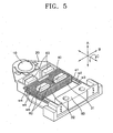
- a blade 20 having an objective lens 10 mounted thereon is movably supported by a plurality of wires W1-W6, i.e., elastic support members, on a holder 50.
- a pair of focus coils 31 and 32, a tracking coil 40, and a magnet 60 are provided as a servo mechanism to drive the blade 20 in a focusing direction A, a tracking direction B, and a tilt direction C.
- current is applied to the tracking coil 40 to drive the blade 20 in the tracking direction B through an interaction with the magnet 60.
- current is identically applied to both focus coils 31 and 32 to drive the blade 20 in the focus direction A.
- different amounts of current are applied to the respective focus coils 31 and 32 to rotate the blade 20 in the tilt direction C.
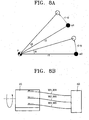
- the wires W1-W6 supporting the blade 20 to be elastically movable with respect to the holder 50 are arranged as shown in Figure 6.
- the wires W1-W6 are symmetrically arranged with respect to a point P, the center of rotation during the tilt control.
- fixed positions of both ends of each wire which is fixed to the holder 50 and the blade 20 are all located at the same distance r from the center of rotation P.
- the fixed positions of the all wires W1-W6 are located on a circumference of the imaginary circle.
- wires can be arranged as shown in Figure 10.
- a first group of wires W2, W3, W6, and W7 are arranged at the same distance from the center P of rotation, and a second group of wires W1, W4, W5, and W8 are arranged.
- a gap G1 between the first and second groups is very smaller than gaps G2 and G3 between the first and second groups.
- the above wire arrangement provides a stable control even when a small amount of an impact or vibration is applied.
- the elastic support members supporting the blade during tilt control by almost removing a difference in the amount of deformation between the elastic support members supporting the blade during tilt control, the elastic support members are prevented from being moved in arbitrary directions when a small impact or vibration is applied or generated. Thus, the control of the position of the objective lens can be stably performed.
Landscapes
- Optical Recording Or Reproduction (AREA)
- Optical Head (AREA)
Claims (2)
- Objektivlinsen-Antriebsvorrichtung für einen optischen Abnehmer, die umfasst:eine Zunge (20), an der eine Objektivlinse (10) angebracht ist;eine Vielzahl elastischer Trageelemente (W1-W6), die die Zunge tragen und sich in Bezug auf die Zunge (20) elastisch bewegen können; undeinen Servomechanismus, der die Zunge nach oben und nach unten, nach links und nach rechts sowie in einer Drehrichtung antreibt, wobei die elastischen Trageelemente (W1-W10) in Paaren (W1, W7; W2, W6; W3, W4; W5, W6; W7, W8; W9, W10) der elastischen Trageelemente gruppiert sind, die so angeordnet sind, dass sie einander in Bezug auf einen Drehmittelpunkt der Zunge (20) zugewandt sind, und Abstände zwischen den elastischen Trageelementen (W1-W6) in den jeweiligen Paaren identisch sind, dadurch gekennzeichnet, dass es drei oder mehr derartige Paare (W1, W2; W2, W5; W3, W4; W5, W6; W7, W8; W9, W10) gibt, bei denen die Abstände zwischen den elastischen Trageelementen (W1-W10) in den jeweiligen Paaren identisch sind.
- Vorrichtung nach Anspruch 1, wobei ein Abstand von jedem elastischen Trageelement zu dem Drehmittelpunkt der Zunge identisch ist.
Applications Claiming Priority (2)
| Application Number | Priority Date | Filing Date | Title |
|---|---|---|---|
| KR2002039781 | 2002-07-09 | ||
| KR1020020039781A KR100881666B1 (ko) | 2002-07-09 | 2002-07-09 | 광픽업의 대물렌즈 구동장치 |
Publications (3)
| Publication Number | Publication Date |
|---|---|
| EP1387355A2 EP1387355A2 (de) | 2004-02-04 |
| EP1387355A3 EP1387355A3 (de) | 2005-08-03 |
| EP1387355B1 true EP1387355B1 (de) | 2007-04-11 |
Family
ID=30113105
Family Applications (1)
| Application Number | Title | Priority Date | Filing Date |
|---|---|---|---|
| EP03253670A Expired - Lifetime EP1387355B1 (de) | 2002-07-09 | 2003-06-11 | Vorrichtung zum Antrieb einer Objektivlinse in einem optischen Kopf |
Country Status (7)
| Country | Link |
|---|---|
| US (1) | US7102836B2 (de) |
| EP (1) | EP1387355B1 (de) |
| JP (1) | JP2004047060A (de) |
| KR (1) | KR100881666B1 (de) |
| CN (1) | CN100339895C (de) |
| DE (1) | DE60313085T2 (de) |
| TW (1) | TWI229330B (de) |
Families Citing this family (10)
| Publication number | Priority date | Publication date | Assignee | Title |
|---|---|---|---|---|
| JP3821105B2 (ja) * | 2003-02-28 | 2006-09-13 | 三菱電機株式会社 | 光学手段駆動装置 |
| US20070274170A1 (en) * | 2004-02-20 | 2007-11-29 | Arima Devices Corporation | Suspension in an Actuator for Displacing a Lens Holder |
| JP2005251295A (ja) * | 2004-03-04 | 2005-09-15 | Funai Electric Co Ltd | 光ピックアップ |
| WO2005096288A1 (ja) * | 2004-03-30 | 2005-10-13 | Pioneer Corporation | ピックアップ用アクチュエータ、ピックアップ装置、記録媒体駆動装置、およびピックアップ用アクチュエータの製造方法 |
| US7911888B2 (en) | 2004-03-30 | 2011-03-22 | Pioneer Corporation | Actuator for pickup, pickup device, recording medium drive device, and method of manufacturing actuator for pickup |
| KR20050100275A (ko) * | 2004-04-13 | 2005-10-18 | 삼성전자주식회사 | 광픽업 액츄에이터 및 이를 채용한 광 기록 및/또는재생기기 |
| JP4137108B2 (ja) * | 2005-09-20 | 2008-08-20 | キヤノン株式会社 | 光ピックアップ装置及び光ディスク装置 |
| JP4508134B2 (ja) | 2006-03-02 | 2010-07-21 | 船井電機株式会社 | 対物レンズアクチュエータ及びそれを備えた光ピックアップ装置 |
| EP1968051A1 (de) * | 2007-03-05 | 2008-09-10 | Deutsche Thomson OHG | Lesekopf für den Zugang zu beweglichen Speichermedien und Laufwerk mit dem Lesekopf |
| US9042042B2 (en) * | 2009-11-18 | 2015-05-26 | Nidec Sankyo Corporation | Lens drive device |
Citations (1)
| Publication number | Priority date | Publication date | Assignee | Title |
|---|---|---|---|---|
| US20020071376A1 (en) * | 2000-10-27 | 2002-06-13 | Katsuhiko Kimura | Objective lens driving device and optical disc apparatus |
Family Cites Families (14)
| Publication number | Priority date | Publication date | Assignee | Title |
|---|---|---|---|---|
| US5724197A (en) * | 1996-08-14 | 1998-03-03 | Eastman Kodak Company | Actuator which compensates for compact disk tilt error |
| JPH10261233A (ja) | 1997-01-14 | 1998-09-29 | Matsushita Electric Ind Co Ltd | 対物レンズ駆動装置 |
| US5905255A (en) * | 1997-01-14 | 1999-05-18 | Matsushita Electric Industrial Co., Ltd. | Objective lens driver |
| TW424913U (en) * | 1998-04-24 | 2001-03-01 | Tdk Corp | Driving apparatus of objectives and its manufacturing method |
| KR20000001133A (ko) * | 1998-06-09 | 2000-01-15 | 윤종용 | 광 픽업 액츄에이터 |
| US6134058A (en) * | 1998-07-03 | 2000-10-17 | Matsushita Electric Industrial Co., Ltd. | Object lens driving device |
| JP3658526B2 (ja) | 1999-09-22 | 2005-06-08 | 株式会社日立メディアエレクトロニクス | 対物レンズ駆動装置ならびにそれを用いた光ディスク装置 |
| US6344936B1 (en) * | 1999-09-29 | 2002-02-05 | Matsushita Electric Industrial Co., Ltd. | Objective lens driving apparatus |
| JP2001110072A (ja) * | 1999-10-12 | 2001-04-20 | Sony Corp | 光学ピックアップ |
| US6801483B2 (en) * | 2000-07-13 | 2004-10-05 | Lg Electronics Inc. | Optical pickup actuator performable tilting operation |
| JP3822434B2 (ja) * | 2000-12-13 | 2006-09-20 | 株式会社リコー | 対物レンズ駆動装置 |
| KR100403586B1 (ko) * | 2001-04-12 | 2003-10-30 | 삼성전자주식회사 | 광픽업 장치 및 그 조립방법 |
| JP3625207B2 (ja) * | 2002-05-23 | 2005-03-02 | 三菱電機株式会社 | 光学手段駆動装置 |
| US7287264B2 (en) * | 2002-06-06 | 2007-10-23 | Ricoh Company, Ltd. | Objective lens drive apparatus with objective lens portion movable along support member axial direction |
-
2002
- 2002-07-09 KR KR1020020039781A patent/KR100881666B1/ko not_active Expired - Fee Related
-
2003
- 2003-05-08 TW TW092112539A patent/TWI229330B/zh not_active IP Right Cessation
- 2003-05-26 JP JP2003148250A patent/JP2004047060A/ja active Pending
- 2003-06-11 EP EP03253670A patent/EP1387355B1/de not_active Expired - Lifetime
- 2003-06-11 DE DE60313085T patent/DE60313085T2/de not_active Expired - Fee Related
- 2003-06-16 CN CNB03149255XA patent/CN100339895C/zh not_active Expired - Fee Related
- 2003-07-08 US US10/614,701 patent/US7102836B2/en not_active Expired - Fee Related
Patent Citations (1)
| Publication number | Priority date | Publication date | Assignee | Title |
|---|---|---|---|---|
| US20020071376A1 (en) * | 2000-10-27 | 2002-06-13 | Katsuhiko Kimura | Objective lens driving device and optical disc apparatus |
Also Published As
| Publication number | Publication date |
|---|---|
| US20040070850A1 (en) | 2004-04-15 |
| DE60313085T2 (de) | 2007-12-27 |
| US7102836B2 (en) | 2006-09-05 |
| CN1471094A (zh) | 2004-01-28 |
| EP1387355A3 (de) | 2005-08-03 |
| TW200401277A (en) | 2004-01-16 |
| TWI229330B (en) | 2005-03-11 |
| JP2004047060A (ja) | 2004-02-12 |
| KR20040005281A (ko) | 2004-01-16 |
| DE60313085D1 (de) | 2007-05-24 |
| CN100339895C (zh) | 2007-09-26 |
| KR100881666B1 (ko) | 2009-02-06 |
| EP1387355A2 (de) | 2004-02-04 |
Similar Documents
| Publication | Publication Date | Title |
|---|---|---|
| US6721110B2 (en) | Optical pickup actuator driving method and apparatus therefor | |
| US7131128B2 (en) | Optical actuator | |
| US7102836B2 (en) | Objective lens driving apparatus for optical pickup | |
| CN1270301C (zh) | 光学驱动装置 | |
| US20020150002A1 (en) | Optical pickup and method of assembling the optical pickup | |
| US5742440A (en) | Actuator with reduced lens tilt error | |
| JP3675356B2 (ja) | 対物レンズ駆動装置 | |
| KR100555510B1 (ko) | 지지부재, 광픽업 액튜에이터 및 광기록/재생 장치 | |
| US5768034A (en) | Lens tilt error reduction actuator | |
| US7907479B2 (en) | Optical pickup actuator in writing and reading device | |
| HUP0300152A2 (hu) | Optikai fejszerelvény-mżködtetż szerkezet, továbbá a mżködtetż szerkezettel ellátott optikai fejszerelvény, valamint az optikai fejszerelvénnyel ellátott optikai felvevż és lejátszó berendezés | |
| US7310289B2 (en) | Actuator for optical pickup of an optical disk drive and a method of using the same | |
| CN1099100C (zh) | 光学传感器物镜传动装置 | |
| US20040123309A1 (en) | Objective lens driving apparatus used with an optical pickup | |
| JP2653360B2 (ja) | 対物レンズ駆動装置 | |
| JP3471475B2 (ja) | 光ヘッド支持機構 | |
| JP2558623B2 (ja) | レンズアクチユエ−タ | |
| JP2897090B2 (ja) | 対物レンズ駆動装置 | |
| US20070159702A1 (en) | Pickup unit and disk drive unit provided with such a pickup unit | |
| JP2003085794A (ja) | 光学ヘッド駆動装置及び光学式情報処理装置 | |
| US20070274170A1 (en) | Suspension in an Actuator for Displacing a Lens Holder | |
| JPH04330644A (ja) | 対物レンズアクチュエータ | |
| JPH11167735A (ja) | 対物レンズ駆動装置 | |
| JPS6310331A (ja) | 対物レンズ支持装置 | |
| EP1883924A1 (de) | Optische aufnahmeeinheit für ein plattenlaufwerk sowie plattenlaufwerk mit einer solchen aufnahmeeinheit |
Legal Events
| Date | Code | Title | Description |
|---|---|---|---|
| PUAI | Public reference made under article 153(3) epc to a published international application that has entered the european phase |
Free format text: ORIGINAL CODE: 0009012 |
|
| 17P | Request for examination filed |
Effective date: 20030624 |
|
| AK | Designated contracting states |
Kind code of ref document: A2 Designated state(s): AT BE BG CH CY CZ DE DK EE ES FI FR GB GR HU IE IT LI LU MC NL PT RO SE SI SK TR |
|
| AX | Request for extension of the european patent |
Extension state: AL LT LV MK |
|
| PUAL | Search report despatched |
Free format text: ORIGINAL CODE: 0009013 |
|
| AK | Designated contracting states |
Kind code of ref document: A3 Designated state(s): AT BE BG CH CY CZ DE DK EE ES FI FR GB GR HU IE IT LI LU MC NL PT RO SE SI SK TR |
|
| AX | Request for extension of the european patent |
Extension state: AL LT LV MK |
|
| AKX | Designation fees paid |
Designated state(s): DE FR GB NL |
|
| 17Q | First examination report despatched |
Effective date: 20051129 |
|
| GRAP | Despatch of communication of intention to grant a patent |
Free format text: ORIGINAL CODE: EPIDOSNIGR1 |
|
| GRAS | Grant fee paid |
Free format text: ORIGINAL CODE: EPIDOSNIGR3 |
|
| GRAA | (expected) grant |
Free format text: ORIGINAL CODE: 0009210 |
|
| AK | Designated contracting states |
Kind code of ref document: B1 Designated state(s): DE FR GB NL |
|
| REG | Reference to a national code |
Ref country code: GB Ref legal event code: FG4D |
|
| REF | Corresponds to: |
Ref document number: 60313085 Country of ref document: DE Date of ref document: 20070524 Kind code of ref document: P |
|
| ET | Fr: translation filed | ||
| PLBE | No opposition filed within time limit |
Free format text: ORIGINAL CODE: 0009261 |
|
| STAA | Information on the status of an ep patent application or granted ep patent |
Free format text: STATUS: NO OPPOSITION FILED WITHIN TIME LIMIT |
|
| 26N | No opposition filed |
Effective date: 20080114 |
|
| PGFP | Annual fee paid to national office [announced via postgrant information from national office to epo] |
Ref country code: DE Payment date: 20080619 Year of fee payment: 6 Ref country code: NL Payment date: 20080603 Year of fee payment: 6 |
|
| PGFP | Annual fee paid to national office [announced via postgrant information from national office to epo] |
Ref country code: FR Payment date: 20080617 Year of fee payment: 6 |
|
| PGFP | Annual fee paid to national office [announced via postgrant information from national office to epo] |
Ref country code: GB Payment date: 20080611 Year of fee payment: 6 |
|
| GBPC | Gb: european patent ceased through non-payment of renewal fee |
Effective date: 20090611 |
|
| NLV4 | Nl: lapsed or anulled due to non-payment of the annual fee |
Effective date: 20100101 |
|
| REG | Reference to a national code |
Ref country code: FR Ref legal event code: ST Effective date: 20100226 |
|
| PG25 | Lapsed in a contracting state [announced via postgrant information from national office to epo] |
Ref country code: FR Free format text: LAPSE BECAUSE OF NON-PAYMENT OF DUE FEES Effective date: 20090630 |
|
| PG25 | Lapsed in a contracting state [announced via postgrant information from national office to epo] |
Ref country code: GB Free format text: LAPSE BECAUSE OF NON-PAYMENT OF DUE FEES Effective date: 20090611 |
|
| PG25 | Lapsed in a contracting state [announced via postgrant information from national office to epo] |
Ref country code: DE Free format text: LAPSE BECAUSE OF NON-PAYMENT OF DUE FEES Effective date: 20100101 |
|
| PG25 | Lapsed in a contracting state [announced via postgrant information from national office to epo] |
Ref country code: NL Free format text: LAPSE BECAUSE OF NON-PAYMENT OF DUE FEES Effective date: 20100101 |