EP1387448B1 - Connecteur électrique pliable - Google Patents
Connecteur électrique pliable Download PDFInfo
- Publication number
- EP1387448B1 EP1387448B1 EP03254685A EP03254685A EP1387448B1 EP 1387448 B1 EP1387448 B1 EP 1387448B1 EP 03254685 A EP03254685 A EP 03254685A EP 03254685 A EP03254685 A EP 03254685A EP 1387448 B1 EP1387448 B1 EP 1387448B1
- Authority
- EP
- European Patent Office
- Prior art keywords
- prongs
- prong
- plug connector
- coupled
- electrical plug
- Prior art date
- Legal status (The legal status is an assumption and is not a legal conclusion. Google has not performed a legal analysis and makes no representation as to the accuracy of the status listed.)
- Expired - Lifetime
Links
Images
Classifications
-
- H—ELECTRICITY
- H01—ELECTRIC ELEMENTS
- H01R—ELECTRICALLY-CONDUCTIVE CONNECTIONS; STRUCTURAL ASSOCIATIONS OF A PLURALITY OF MUTUALLY-INSULATED ELECTRICAL CONNECTING ELEMENTS; COUPLING DEVICES; CURRENT COLLECTORS
- H01R35/00—Flexible or turnable line connectors, i.e. the rotation angle being limited
- H01R35/04—Turnable line connectors with limited rotation angle with frictional contact members
-
- H—ELECTRICITY
- H01—ELECTRIC ELEMENTS
- H01R—ELECTRICALLY-CONDUCTIVE CONNECTIONS; STRUCTURAL ASSOCIATIONS OF A PLURALITY OF MUTUALLY-INSULATED ELECTRICAL CONNECTING ELEMENTS; COUPLING DEVICES; CURRENT COLLECTORS
- H01R13/00—Details of coupling devices of the kinds covered by groups H01R12/70 or H01R24/00 - H01R33/00
- H01R13/648—Protective earth or shield arrangements on coupling devices, e.g. anti-static shielding
- H01R13/652—Protective earth or shield arrangements on coupling devices, e.g. anti-static shielding with earth pin, blade or socket
-
- H—ELECTRICITY
- H01—ELECTRIC ELEMENTS
- H01R—ELECTRICALLY-CONDUCTIVE CONNECTIONS; STRUCTURAL ASSOCIATIONS OF A PLURALITY OF MUTUALLY-INSULATED ELECTRICAL CONNECTING ELEMENTS; COUPLING DEVICES; CURRENT COLLECTORS
- H01R2103/00—Two poles
-
- H—ELECTRICITY
- H01—ELECTRIC ELEMENTS
- H01R—ELECTRICALLY-CONDUCTIVE CONNECTIONS; STRUCTURAL ASSOCIATIONS OF A PLURALITY OF MUTUALLY-INSULATED ELECTRICAL CONNECTING ELEMENTS; COUPLING DEVICES; CURRENT COLLECTORS
- H01R24/00—Two-part coupling devices, or either of their cooperating parts, characterised by their overall structure
- H01R24/28—Coupling parts carrying pins, blades or analogous contacts and secured only to wire or cable
- H01R24/30—Coupling parts carrying pins, blades or analogous contacts and secured only to wire or cable with additional earth or shield contacts
Definitions
- Embodiments of the present invention generally relate to an electrical plug connector. More particularly, embodiments of the present invention relate to an electrical plug connector with retractable prongs.
- Electrical devices typically utilize an electrical plug connector in order to receive power from an electrical wall outlet or other power source. Electrical devices are often stored when not in use and/or during transfer from one place to another, and corresponding electrical plug connectors are generally stored with the electrical devices to enable use of the electrical devices upon reaching a destination. For example, many students and business persons carry personal computers in cases while traveling to and from classes or work. In another example, air travelers may pack electrical devices such as curling irons and electric shavers in their luggage. Because the prongs of an electrical plug connector protrude from its outer body, electrical plug connectors with fixed prongs are typically awkward in shape and may occupy a significant amount of space when stored in a confined area, such as a computer bag or a piece of carry-on luggage. Moreover; the prongs of an electrical plug connector generally have sharp edges that may pose a safety hazard.
- a foldable electrical plug connector includes two retractable prongs.
- the two prongs are connected by a common rod about which the prongs are rotated from a first position, in which the prongs extend outward from a first face, to a second position in which the prongs fit into a groove within a connector housing.
- the prongs may be held in a retracted state by an orienting base (in the '271 Patent), a spring force (in the '178 Patent), notches (in the '886 Patent), or a tongue (in the '449 Patent).
- U.S. Pat. Nos. 6,126,460 (“the '460 Patent”), 5,967,807 (“the '807 Patent”), and 4,997,381 (“the '381 Patent”) describe a dual-use plug with two sets of two prongs.
- a primary plug may be retracted as a unit into a cavity in a power supply housing and the prongs of a secondary plug may be retracted into a cavity in the housing of the primary plug.
- the prongs of the primary plug are joined by a casing that rotates with the prongs to place the primary plug in the retracted state.
- a TeleAdapt press release dated March 22, 2001 discusses a folding plug product in which a three prong foldable electrical plug connector folds into its housing along an axis of rotation in the middle of the plug body. The three prongs are joined by a portion of the housing.
- this type of plug body appears to occupy more space than a typical electrical plug connector, rather than save space.
- U.K. Patent Application No. 9514143.8 (“the '143 UK Application”) and U.K. Patent Application No. 8901083.9 (“the '083 UK Application”) each describe a three-prong foldable electrical plug connector, whose prongs are pivotally retracted into recesses in a body of the plug.
- a ball-and-spring mechanism is used to maintain each prong in an extended position.
- the '143 UK Application shows all three prongs fold down in the same direction; whereas, in the '083 Application, a third prong folds in a direction opposite to the direction in which the first two prongs fold.
- US Patent No. 5,611,701 discloses a three-prong plug device in which the prongs are movable between collapsed and extended positions by a linkage that includes pins on which the prongs are pivotable. In the collapsed position the prongs are received in recesses in the plug casing.
- GB-A-2215531 discloses an electrical plug with folding pins.
- the pins are folded into the plug casing by a pivoting action that is controlled by a sliding member.
- US Patent No. 6,241,538 discloses a power supply plug structure for a notebook computer including two elongated sheet-shaped connecting legs. Each of the two connecting legs is pivotally mounted in a receiving recess, and includes a rotation shaft having two ends, each having a pivot axle. A plurality of meshing driven gears each mesh with the drive gear of the rotation shaft of each of the two connecting legs.
- an electrical plug connector including a plurality of prongs capable of being coupled to an electrical power source and further capable of being retracted, a body having at least one recess; a power cable configured to transmit power received from the electrical power source to an electrical device; and a mechanism to which each of the plurality of prongs is coupled to retract the plurality of prongs when a force is applied to one of the plurality of prongs, wherein at least a portion of each of the plurality of prongs is contained within the at least one recess when the plurality of prongs is retracted, characterized in that:
- a foldable electrical plug connector reduces the volume of space that is typically used to store a conventional electrical plug connector.
- Prongs of the foldable electrical plug connector may be retracted by applying a force to one of the prongs. Furthermore, when the foldable electrical plug connector is in a retracted state, one of the prongs may protrude beyond a body 140 of the foldable electrical plug connector to facilitate extension of the prongs.
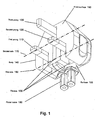
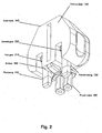
- Fig. 1 and Fig. 2 illustrate a foldable electrical plug connector according to an embodiment of the present invention.
- Fig. 1 shows the foldable electrical plug connector in an extended state
- Fig. 2 illustrates the foldable electrical plug connector in a retracted state.
- the foldable electrical plug connector shown in both Figs. 1 and 2 may include multiple prongs 110, 120, and 130, a body 140, a gearing mechanism (340 in Fig. 3 ), and a power cable 180 through which electrical power is transmitted to an electrical device. While only three prongs are shown, embodiments of the invention may have a greater or lesser number of prongs depending on the configuration of the power source to which the electrical plug connector is intended to be coupled.
- the prongs 110, 120, and 130 may be coupled to an electrical power source when in the extended state and may be decoupled from the power source before they are retracted.
- the prongs 110, 120, and 130 may be made of brass, copper, or a similar electrically conductive material, and may be plated with a material to prevent corrosion, such as nickel.
- the prongs may include a first prong 110, a second prong 120, and a third prong 130.
- the first prong 110 may be extended to couple to a positive terminal of the electrical power source, and the second prong 120 may be extended to couple to a negative terminal of the electrical power source.
- the third prong 130 may be configured to be coupled to a ground potential, such as a ground terminal of the electrical power source. In this way, electrical power may be received at the prongs 110, 120, and 130 and transmitted to an electrical device through a power cable 180.
- the prongs 110, 120, and 130 may be electrically coupled to conductive wires in the power cable 180.
- the body 140 may be made of a non-conductive material and suitably light and rigid material, such as ABS plastic.
- the body 140 may have several outer surfaces, including a front surface 190 which may be in contact with or proximate to a face plate of an electrical outlet or a portion of some other power source when the prongs 110, 120, and 130 are inserted into the electrical outlet.
- a front surface 190 which may be in contact with or proximate to a face plate of an electrical outlet or a portion of some other power source when the prongs 110, 120, and 130 are inserted into the electrical outlet.
- front surface is meant only to denote that the prongs 110, 120 and 130 extend from surface 190 when extended and not to connote any relationship between front surface 190 and the remaining surfaces of the body 140 or to connote that the plug connector must be configured in a particular way during use.
- the body 140 may have at least one recess 150 into which the prongs 110, 120, and 130 may be retracted. As shown, the body 140 may have three recesses 150, each corresponding to one of the prongs 110, 120, and 130. The prongs 110, 120, and 130 may extend beyond the front surface 190 of the body 140 when the plug connector is in the extended state. The depth of the recesses 150 may be selected based on the dimensions of the prongs 110, 120 and 130 such that none or only portions of the prongs protrudes from a front surface 190 of the body 140 when the prongs 110, 120 and 130 are in the retracted state but a sufficiently large portion of the prongs extends beyond the front surface 190 in the extended state to couple to the desired power source.
- each of the prongs 110, 120, and 130 may retract in the same direction.
- the power cable 180 may be coupled to a surface 195 of the body 140.
- at least one of the prongs 110, 120, and 130 may lie proximate the power cable 180 when the foldable electrical plug connector 100 is in a retracted state.
- the prongs 110, 120, and 130 may remain electrically coupled to the power cable 180 when the foldable electrical plug connector 100 is in the retracted state.
- the prongs 110, 120, and 130 may be decoupled from the power cable 180 when the foldable electrical plug connector 100 is in the retracted state.
- the prongs 110, 120, and 130 may disconnect from an electrical contact in the body 140 when the prongs 110, 120, and 130 pivot.
- the prongs 110, 120, and 130 may extend perpendicular to the surface 190 of the body 140. In the retracted state, the prongs 110, 120, and 130 may be parallel to the power cable 180.
- the power cable 180 is generally flexible. Therefore, it is understood that "parallel to the power cable 180" means parallel with a portion of the power cable 180 near the point at which the power cable 180 is coupled to the body 140 of the foldable electrical plug connector 100.
- At least one of the prongs 110, 120, and 130 may be entirely within the at least one recess 150 when the foldable electrical plug connector 100 is in the retracted state.
- prong 130 is illustrated as being completely contained within its corresponding recess 150.
- at least one of the prongs 110, 120 and 130 may extend beyond a surface 195 of the body 140 when the plug connector is in the retracted state (as is the case for prongs 110 and 120). This design facilitates extension of the prongs 110, 120, and 130.
- a user may apply a force upon a portion of a prong that extends beyond the surface 195 of the body 140, such that the prong is rotated about an axis that extends through a base of the prong.
- one or more of the prongs may extend beyond a different surface of the body 140, including, for example, the front surface 190.
- the exposed portions may include a gripping feature, such as a notch, to aid a user in applying force to the prong 110, 120 or 130.
- the third prong 130 may not be aligned with both the first prong 110 and the second prong 120.
- the first prong 110 and the second prong 120 may rotate about a first axis 160, and the third prong 130 may rotate about a second axis 170.
- the first axis 160 may extend through a base of the first prong 110 and a base of the second prong 120, and the second axis 170 may extend through a base of the third prong 130.
- the first axis 160 and the second axis 170 may lie parallel to each other.
- the third prong 130 may retract in a first direction opposite to a second direction in which the first prong 110 and the second prong 120 retract.
- the prongs 110, 120 and 130 may be retracted in other than a pivoting motion, e.g., by sliding the prongs 110, 120 and 130 into the recesses 150.
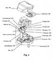
- Fig. 3 illustrates an exploded view of a foldable electrical plug connector according to an embodiment of the present invention.
- the gearing mechanism 340 may include a plurality of axles 310, 320 and 330.
- Each of the plurality of axles 310, 320 and 330 may be coupled to at least one of multiple gears 210, 220, 230 and 240 and at least one of the prongs 110, 120, and 130.
- the gears 210, 220, 230 and 240 may be coupled to the axles 310, 320 and 330 at different locations on the axles 310, 320 and 330.
- first axle 310 is shown as coupled to first gear 210 and second axle 320 is shown as coupled to second gear 220 at locations proximate the center points of the first and second axles 310 and 320.
- third axle 330 is shown as coupled to third gear 230 and fourth gear 240 proximate the endpoints of the third axle 330.
- the gears 210, 220, 230 and 240 may be coupled directly to the axles 310, 320, and 330 (as illustrated by third axle 330 and third and fourth gears 230 and 240).
- the gears 210, 220, 230 and 240 may be coupled to collar portions 350, which may in turn be coupled to the axles 310, 320, 330 (as illustrated by first and second axles 310 and 320 and first and second gears 210 and 220).
- the gears 205 may rotate in the plane of motion of the prongs 110, 120, and 130.
- An axle 310, 320 or 330 may be coupled to one of the prongs 110, 120, and 130 by adhesive, solder, compression fitting, or any other suitable joining means.
- the axle 310, 320 or 330 may pass through an opening in the prong 110, 120, or 130.
- each of the prongs 110, 120 and 130 may have a collar portion 350 configured to fit around the axle 310, 320 or 330.
- the gearing mechanism 340 may be configured to cause simultaneous retraction and/or extension of the prongs 110, 120, and 130.
- the simultaneous retraction and/or extension may occur when a force is applied to one of the prongs 110, 120, and 130.
- the prongs 110, 120, and 130 may be rotatably mounted to the gearing mechanism 340.
- the resulting torque may also be transmitted to the other axles 310, 320 and/or 330 via the gears 210, 220, 230 and 240 coupled to the axles and the intermediate gears 250 and 260.
- the gears 210, 220, 230, 240, 250 and 260 may be intermeshed.
- the transmitted torque may cause the remaining prongs to retract in concert with the prong 110, 120, or 130 to which the force was applied.
- Fig. 3 depicts some of the gears 210, 220, 230, 240, 250 and 260 as having teeth around only a portion thereof, the gears 210, 220, 230, 240, 250 and 260 may have a complete set of teeth around the entire circumference of each gear 210, 220, 230, 240, 250 and 260.
- the gearing mechanism 340 may be configured such that the first prong 110 and the second prong 120 retract in a direction opposite that of the third prong 130.
- Intermediate gears 350 and 360 may be included in embodiments in such embodiments.
- the gearing mechanism 340 may not include intermediate gears 350 and 360. This may be the case, for example, in embodiments of the invention in which the prongs 110, 120 and 130 do not all retract in the same direction.
- the plurality of axles 310, 320 and 330 and/or gears 210, 220, 230, 240, 250 and 260 may be composed of any suitable material.
- some or all of the axles 310, 320 and 330 and/or gears 210, 220, 230, 240, 250 and 260 may be electrically conductive.
- some or all of the plurality of axles 310, 320 and 330 and/or gears 210, 220, 230, 240, 250 and 260 may be electrically non-conductive. If an axle is electrically conductive, then a gear that is coupled to the axle is generally electrically non-conductive to avoid shorting two prongs together.
Landscapes
- Details Of Connecting Devices For Male And Female Coupling (AREA)
Claims (13)
- Connecteur à fiche électrique, englobant plusieurs broches (110 120, 230) pouvant être accouplées à une source d'énergie électrique et pouvant être rétractées, un corps (140), comportant au moins un évidement (150); un câble d'alimentation (180) configuré de sorte à transmettre l'énergie reçue de la source d'énergie électrique vers un dispositif électrique ; et un mécanisme auquel est accouplée chacune des plusieurs broches (110, 120, 130) pour rétracter les plusieurs broches (110, 120, 130) lors de l'application d'une force à l'une des plusieurs broches (110, 120, 130), au moins une partie de chacune des plusieurs broches (110, 120, 130) étant contenue dans le au moins un évidement (150) lorsque les plusieurs broches (110, 120, 130) sont rétractées ; caractérisé en ce que :les plusieurs broches englobent une première broche (110), une deuxième broche (120) et une troisième broche (130) ; etle mécanisme englobe la première broche (110) accouplée à un premier essieu (310), la deuxième broche (120) accouplée à un deuxième essieu (320), la troisième broche (130) accouplée à un troisième essieu (330), un premier engrenage (210) accouplé au premier essieu (310), un deuxième engrenage (220) accouplé au deuxième essieu (320) et un troisième engrenage (230) ainsi qu'un quatrième engrenage (220) accouplés au troisième essieu (330), le premier engrenage (210) étant accouplé au troisième engrenage (230) et le deuxième engrenage (220) étant accouplé au quatrième engrenage (240), de sorte que les plusieurs broches (110, 120, 130) sont rétractées lors de l'application d'une force à l'une des plusieurs broches (110, 120, 130).
- Connecteur à fiche électrique selon la revendication 1, dans lequel un engrenage intermédiaire (250, 260) est en contact rotatif avec le premier engrenage (210, 220) et le troisième engrenage (230, 240).
- Connecteur à fiche électrique selon la revendication 1, dans lequel la troisième broche (130) n'est pas alignée avec la première broche (110) et la deuxième broche (120).
- Connecteur à fiche électrique selon la revendication 1, dans lequel la troisième broche (130) est configurée de sorte à être accouplée à un potentiel de terre.
- Connecteur à fiche électrique selon la revendication 1, dans lequel la troisième broche (130) se rétracte dans une première direction opposée à une deuxième direction dans laquelle la première broche (110) et la deuxième broche (120) se rétractent.
- Connecteur à fiche électrique selon la revendication 1, dans lequel la première broche (110) est configurée de sorte à être accouplée à une borne positive d'une source d'énergie, la deuxième broche (120) étant configurée de sorte à être accouplée à une borne négative de la source d'énergie.
- Connecteur à fiche électrique selon la revendication 1, dans lequel chacune des plusieurs broches (110, 120, 130) se rétracte dans la même direction.
- Connecteur à fiche électrique selon la revendication 1, dans lequel le câble d'alimentation (180) comporte des fils conducteurs accouplés électriquement aux plusieurs broches (110, 120, 130).
- Connecteur à fiche électrique selon la revendication 8, dans lequel une partie de la au moins une des plusieurs broches (110, 120, 130) s'étend au-delà d'une surface (195) du corps (140) dans l'état rétracté, la partie étant située près du câble d'alimentation (180).
- Connecteur à fiche électrique selon la revendication 8, dans lequel au moins une des plusieurs broches (110, 120, 130) reste accouplée électriquement au câble d'alimentation (180) lorsque les plusieurs broches (110, 120, 130) sont rétractées.
- Connecteur à fiche électrique selon la revendication 8, dans lequel au moins une des plusieurs broches (110, 120, 130) est désaccouplée électriquement du câble d'alimentation (180) lorsque les plusieurs broches (110, 120, 130) sont rétractées.
- Connecteur à fiche électrique selon la revendication 1, dans lequel au moins une des plusieurs broches (110, 120, 130) déborde au-delà d'une surface (195) du corps externe (140) du connecteur à fiche électrique lorsque les plusieurs broches (110, 120, 130) sont rétractées.
- Connecteur à fiche électrique selon la revendication 1, dans lequel au moins une des plusieurs broches (110, 120, 130) est entièrement contenue dans au moins un évidement (150) lorsque les plusieurs broches (110, 120, 130) sont rétractées.
Applications Claiming Priority (2)
| Application Number | Priority Date | Filing Date | Title |
|---|---|---|---|
| US210364 | 2002-08-01 | ||
| US10/210,364 US6939150B1 (en) | 2002-08-01 | 2002-08-01 | Foldable electrical plug connector |
Publications (3)
| Publication Number | Publication Date |
|---|---|
| EP1387448A2 EP1387448A2 (fr) | 2004-02-04 |
| EP1387448A3 EP1387448A3 (fr) | 2004-02-11 |
| EP1387448B1 true EP1387448B1 (fr) | 2009-05-13 |
Family
ID=30115236
Family Applications (1)
| Application Number | Title | Priority Date | Filing Date |
|---|---|---|---|
| EP03254685A Expired - Lifetime EP1387448B1 (fr) | 2002-08-01 | 2003-07-26 | Connecteur électrique pliable |
Country Status (3)
| Country | Link |
|---|---|
| US (1) | US6939150B1 (fr) |
| EP (1) | EP1387448B1 (fr) |
| DE (1) | DE60327584D1 (fr) |
Cited By (1)
| Publication number | Priority date | Publication date | Assignee | Title |
|---|---|---|---|---|
| US9438052B1 (en) | 2015-03-27 | 2016-09-06 | Ellen Louise Cole | Mobile device holder-charger |
Families Citing this family (37)
| Publication number | Priority date | Publication date | Assignee | Title |
|---|---|---|---|---|
| US9153960B2 (en) | 2004-01-15 | 2015-10-06 | Comarco Wireless Technologies, Inc. | Power supply equipment utilizing interchangeable tips to provide power and a data signal to electronic devices |
| US7646107B2 (en) | 2004-09-30 | 2010-01-12 | Targus Group Internatnional, Inc. | Programmable power adaptor |
| TWM271291U (en) * | 2004-10-04 | 2005-07-21 | Inventec Multimedia & Telecom | Connector |
| US7134887B1 (en) * | 2005-06-30 | 2006-11-14 | Microsoft Corporation | Wall socket connector for AC adapters |
| WO2007113541A2 (fr) * | 2006-04-03 | 2007-10-11 | Thinplug Limited | Prise |
| GB2436899B (en) * | 2006-04-03 | 2009-06-17 | Zihni Yalcin | Plug |
| CN101154783B (zh) * | 2006-09-29 | 2010-07-21 | 台达电子工业股份有限公司 | 可折叠式电连接器及使用该电连接器的电源供应装置 |
| US7303416B1 (en) * | 2007-02-07 | 2007-12-04 | Sheng-Hsin Liao | Compound conversion plug structure with adjustable angle and adapter |
| EP1978607A1 (fr) * | 2007-04-03 | 2008-10-08 | Modelabs Technologies Limited | Chargeur électrique muni d'un plot de connexion articulé |
| US7604492B1 (en) * | 2008-11-21 | 2009-10-20 | Cheng Uei Precision Industry Co., Ltd. | Power supply adapter |
| US8213204B2 (en) | 2009-04-01 | 2012-07-03 | Comarco Wireless Technologies, Inc. | Modular power adapter |
| JP5279649B2 (ja) * | 2009-07-31 | 2013-09-04 | 三洋電機株式会社 | 電源接続装置 |
| TWI427875B (zh) * | 2009-10-28 | 2014-02-21 | Powertech Ind Co Ltd | 具有旋轉及摺合的插頭 |
| US8366461B2 (en) * | 2009-10-28 | 2013-02-05 | Powertech Industrial Co., Ltd. | Electrical plug having rotatable prongs |
| US8354760B2 (en) | 2009-10-28 | 2013-01-15 | Comarco Wireless Technologies, Inc. | Power supply equipment to simultaneously power multiple electronic device |
| CN102074868B (zh) * | 2009-11-19 | 2013-06-05 | 胜德国际研发股份有限公司 | 具有旋转及折合的插头 |
| USD620889S1 (en) * | 2010-01-25 | 2010-08-03 | Research In Motion Limited | Plug |
| JP5647729B2 (ja) | 2010-05-20 | 2015-01-07 | クック メディカル テクノロジーズ エルエルシーCook Medical Technologies Llc | 医療処置において使用される電気デバイス用リードシステム |
| US9130384B2 (en) * | 2011-10-06 | 2015-09-08 | Prong, Inc. | Smart phone and/or consumer electronics device charger system |
| US8821199B2 (en) | 2012-07-25 | 2014-09-02 | Targus Group International, Inc. | Multi-prong power tip adaptor |
| US8550827B1 (en) | 2012-07-25 | 2013-10-08 | Targus Group International, Inc. | Multi-sleeve power tips |
| WO2015117140A1 (fr) * | 2014-02-03 | 2015-08-06 | Volex Plc | Connecteur électrique à broches pliantes |
| US9331441B2 (en) * | 2014-06-17 | 2016-05-03 | Apple Inc. | Power adapter with retractable prongs |
| HK1197634A2 (en) * | 2014-10-07 | 2015-01-30 | Cord-It Limited | Plug apparatus with movable pin |
| TWI559632B (zh) * | 2015-01-05 | 2016-11-21 | 勝德國際研發股份有限公司 | 萬用插座 |
| US9977462B2 (en) * | 2016-09-09 | 2018-05-22 | Wafr Ip Llc | Universal phone battery chargers for mobile cellphones and like devices |
| CA2961248C (fr) * | 2017-03-17 | 2018-05-01 | Cable Gear Holdings Llc | Prise electrique et adaptateur dote de broches retractables |
| CN109411939B (zh) * | 2017-08-16 | 2020-09-11 | 康塔克整合解决股份有限公司 | 插头装置 |
| GB201817491D0 (en) * | 2018-10-26 | 2018-12-12 | Design Narrative Ltd | Power adaptor |
| GB201821280D0 (en) * | 2018-12-28 | 2019-02-13 | Lst Engineering Ltd | Lockable safety plug |
| USD936019S1 (en) * | 2019-04-30 | 2021-11-16 | Design Pool Limited | Wall adapter |
| CN111076150A (zh) * | 2020-01-06 | 2020-04-28 | 上海顿格电子贸易有限公司 | 可旋转的插拔式灯头 |
| CN111478110A (zh) * | 2020-04-13 | 2020-07-31 | 东莞市佳旅电器有限公司 | 一种转换插头伸出机构 |
| CN112864689B (zh) * | 2021-01-05 | 2023-06-23 | 深圳市绿联科技股份有限公司 | 一种可收纳的电力插头、插线板和电器 |
| CN114498863B (zh) * | 2022-04-01 | 2022-08-05 | 东莞市奥海科技股份有限公司 | 充电器 |
| CN118174077A (zh) * | 2024-03-19 | 2024-06-11 | 深圳市绿联科技股份有限公司 | 一种插脚联动翻转插头 |
| CN121440309A (zh) * | 2024-07-30 | 2026-01-30 | 贝尔金国际股份有限公司 | 可折叠的电插头及相关方法 |
Citations (1)
| Publication number | Priority date | Publication date | Assignee | Title |
|---|---|---|---|---|
| US6241538B1 (en) * | 2000-06-08 | 2001-06-05 | Gme-Tech Co., Ltd. | Power supply plug structure for a notebook computer |
Family Cites Families (23)
| Publication number | Priority date | Publication date | Assignee | Title |
|---|---|---|---|---|
| US1386884A (en) | 1921-08-09 | Electrical-fittings connection | ||
| DE1048189B (de) | 1956-08-06 | 1958-12-31 | Otto Huebner | Elektrischer Rasierapparat |
| US3134631A (en) * | 1960-11-04 | 1964-05-26 | Robert A Whalen | Electrical connector plug |
| US3958849A (en) * | 1974-05-13 | 1976-05-25 | Blairsdale Donald A | Electrical plug |
| US4075458A (en) | 1976-07-08 | 1978-02-21 | The Gillette Company | Compact hair curling iron |
| US4467263A (en) | 1983-01-31 | 1984-08-21 | Pittway Corporation | Rechargeable battery-powered flashlight system |
| GB8403294D0 (en) | 1984-02-08 | 1984-03-14 | Rumble C S J | Electrical connectors |
| US4697070A (en) | 1985-04-22 | 1987-09-29 | Omron Tateisi Electronics Co. | Contact lens sterilization device |
| GB8801131D0 (en) | 1988-01-19 | 1988-02-17 | Byford T | Fold down electrical plug |
| US4997381A (en) | 1990-02-26 | 1991-03-05 | Oh Tae J | Dual functional, electrical plug use in conjunction with an electric appliance |
| US5401178A (en) * | 1993-09-03 | 1995-03-28 | Delta Electronics, Inc. | Integrated foldable electric plug connector |
| TW255989B (en) * | 1994-02-24 | 1995-09-01 | Asian Micro Sources Inc | Collapsible prong plug device for battery charger |
| TW268155B (en) * | 1994-02-24 | 1996-01-11 | Asian Micro Sources Inc | Collapsible plug device for battery charger |
| US5494449A (en) | 1994-09-01 | 1996-02-27 | Chioo; Ming D. | Power supply device for portable computers |
| US5613863A (en) * | 1995-05-18 | 1997-03-25 | Motorola, Inc. | Power transformer |
| GB2303256A (en) | 1995-07-11 | 1997-02-12 | Paul Philip Eden | Plug with folding pins |
| US5967807A (en) | 1997-08-20 | 1999-10-19 | Formosa Electronic Industries Inc. | AC/DC electric adapter with the large and small plugs |
| US6059584A (en) | 1998-09-10 | 2000-05-09 | Ericsson, Inc. | Swiveling electrical plug assembly |
| US6126460A (en) | 1999-07-30 | 2000-10-03 | Formosa Electronic Industries Inc. | Safety dual plug structure |
| DE10102713B4 (de) * | 2001-01-22 | 2004-12-09 | Friwo Gerätebau Gmbh | Steckernetzteil mit miniaturisierter Primärkontaktierung |
| USD454537S1 (en) | 2001-02-21 | 2002-03-19 | Phihong Usa Corporation | Enclosure for a switching power supply |
| US6312271B1 (en) | 2001-03-09 | 2001-11-06 | Delta Electronics, Inc. | Connector having foldable plug |
| US6780034B2 (en) * | 2002-11-19 | 2004-08-24 | Shiroshita Industrial Co., Ltd. | Coalescent type power supply conversion plug adapter |
-
2002
- 2002-08-01 US US10/210,364 patent/US6939150B1/en not_active Expired - Fee Related
-
2003
- 2003-07-26 EP EP03254685A patent/EP1387448B1/fr not_active Expired - Lifetime
- 2003-07-26 DE DE60327584T patent/DE60327584D1/de not_active Expired - Lifetime
Patent Citations (1)
| Publication number | Priority date | Publication date | Assignee | Title |
|---|---|---|---|---|
| US6241538B1 (en) * | 2000-06-08 | 2001-06-05 | Gme-Tech Co., Ltd. | Power supply plug structure for a notebook computer |
Cited By (1)
| Publication number | Priority date | Publication date | Assignee | Title |
|---|---|---|---|---|
| US9438052B1 (en) | 2015-03-27 | 2016-09-06 | Ellen Louise Cole | Mobile device holder-charger |
Also Published As
| Publication number | Publication date |
|---|---|
| DE60327584D1 (de) | 2009-06-25 |
| EP1387448A2 (fr) | 2004-02-04 |
| US6939150B1 (en) | 2005-09-06 |
| EP1387448A3 (fr) | 2004-02-11 |
Similar Documents
| Publication | Publication Date | Title |
|---|---|---|
| EP1387448B1 (fr) | Connecteur électrique pliable | |
| US8491317B2 (en) | Compact all-in-one power adapter | |
| US5967807A (en) | AC/DC electric adapter with the large and small plugs | |
| US7556535B2 (en) | Adapter having connecting arms | |
| US4954091A (en) | Convertible ground safety plug | |
| US20060170393A1 (en) | Portable battery charger in shape of thumb | |
| US10181680B1 (en) | Securable power adapter | |
| JP2014041825A (ja) | 伸縮変形可能なusb接続装置及び伸縮変形可能な接続装置 | |
| TWM426181U (en) | Power plug apparatus capable of changing directions | |
| EP1999540A2 (fr) | Prise double c.a./c.c. isolée | |
| US10950991B2 (en) | Multiple unit charge cord assembly | |
| CN112636069B (zh) | 电源适配器 | |
| CN216850425U (zh) | 电力插头 | |
| CN207732480U (zh) | 一种单手易拔的折叠充电器 | |
| CN210692823U (zh) | 折叠转换电源插头 | |
| CN220984983U (zh) | 三插脚折叠收纳结构及三插脚插头 | |
| KR20190119747A (ko) | 휴대용 단말 충전기용 전기 플러그 | |
| CN108565926A (zh) | 一种无线充电移动电源 | |
| EP3131159B1 (fr) | Bande d'alimentation rotative et extensible | |
| JP2008198498A (ja) | 海外コンセント用変換プラグ | |
| CN2877086Y (zh) | 多种插针合一的电源插头结构 | |
| CN212571528U (zh) | 电源适配器及电子设备组件 | |
| GB2609270A (en) | Foldable plug and charger | |
| US20040053536A1 (en) | Plug device | |
| CN222366104U (zh) | 一种旋转折叠充电器 |
Legal Events
| Date | Code | Title | Description |
|---|---|---|---|
| PUAI | Public reference made under article 153(3) epc to a published international application that has entered the european phase |
Free format text: ORIGINAL CODE: 0009012 |
|
| PUAL | Search report despatched |
Free format text: ORIGINAL CODE: 0009013 |
|
| AK | Designated contracting states |
Kind code of ref document: A2 Designated state(s): AT BE BG CH CY CZ DE DK EE ES FI FR GB GR HU IE IT LI LU MC NL PT RO SE SI SK TR |
|
| AX | Request for extension of the european patent |
Extension state: AL LT LV MK |
|
| AK | Designated contracting states |
Kind code of ref document: A3 Designated state(s): AT BE BG CH CY CZ DE DK EE ES FI FR GB GR HU IE IT LI LU MC NL PT RO SE SI SK TR |
|
| AX | Request for extension of the european patent |
Extension state: AL LT LV MK |
|
| 17P | Request for examination filed |
Effective date: 20040811 |
|
| AKX | Designation fees paid |
Designated state(s): DE FR GB IT |
|
| 17Q | First examination report despatched |
Effective date: 20041026 |
|
| GRAP | Despatch of communication of intention to grant a patent |
Free format text: ORIGINAL CODE: EPIDOSNIGR1 |
|
| GRAS | Grant fee paid |
Free format text: ORIGINAL CODE: EPIDOSNIGR3 |
|
| GRAA | (expected) grant |
Free format text: ORIGINAL CODE: 0009210 |
|
| AK | Designated contracting states |
Kind code of ref document: B1 Designated state(s): DE FR GB IT |
|
| REG | Reference to a national code |
Ref country code: GB Ref legal event code: FG4D |
|
| REF | Corresponds to: |
Ref document number: 60327584 Country of ref document: DE Date of ref document: 20090625 Kind code of ref document: P |
|
| PLBE | No opposition filed within time limit |
Free format text: ORIGINAL CODE: 0009261 |
|
| STAA | Information on the status of an ep patent application or granted ep patent |
Free format text: STATUS: NO OPPOSITION FILED WITHIN TIME LIMIT |
|
| 26N | No opposition filed |
Effective date: 20100216 |
|
| PG25 | Lapsed in a contracting state [announced via postgrant information from national office to epo] |
Ref country code: IT Free format text: LAPSE BECAUSE OF FAILURE TO SUBMIT A TRANSLATION OF THE DESCRIPTION OR TO PAY THE FEE WITHIN THE PRESCRIBED TIME-LIMIT Effective date: 20090513 |
|
| PGFP | Annual fee paid to national office [announced via postgrant information from national office to epo] |
Ref country code: GB Payment date: 20130624 Year of fee payment: 11 |
|
| PGFP | Annual fee paid to national office [announced via postgrant information from national office to epo] |
Ref country code: DE Payment date: 20130731 Year of fee payment: 11 |
|
| PGFP | Annual fee paid to national office [announced via postgrant information from national office to epo] |
Ref country code: FR Payment date: 20130712 Year of fee payment: 11 |
|
| REG | Reference to a national code |
Ref country code: DE Ref legal event code: R119 Ref document number: 60327584 Country of ref document: DE |
|
| GBPC | Gb: european patent ceased through non-payment of renewal fee |
Effective date: 20140726 |
|
| REG | Reference to a national code |
Ref country code: FR Ref legal event code: ST Effective date: 20150331 |
|
| PG25 | Lapsed in a contracting state [announced via postgrant information from national office to epo] |
Ref country code: DE Free format text: LAPSE BECAUSE OF NON-PAYMENT OF DUE FEES Effective date: 20150203 |
|
| REG | Reference to a national code |
Ref country code: DE Ref legal event code: R119 Ref document number: 60327584 Country of ref document: DE Effective date: 20150203 |
|
| PG25 | Lapsed in a contracting state [announced via postgrant information from national office to epo] |
Ref country code: GB Free format text: LAPSE BECAUSE OF NON-PAYMENT OF DUE FEES Effective date: 20140726 Ref country code: FR Free format text: LAPSE BECAUSE OF NON-PAYMENT OF DUE FEES Effective date: 20140731 |