EP1387922B1 - Spannvorrichtung für ein rolltor - Google Patents
Spannvorrichtung für ein rolltor Download PDFInfo
- Publication number
- EP1387922B1 EP1387922B1 EP02734344A EP02734344A EP1387922B1 EP 1387922 B1 EP1387922 B1 EP 1387922B1 EP 02734344 A EP02734344 A EP 02734344A EP 02734344 A EP02734344 A EP 02734344A EP 1387922 B1 EP1387922 B1 EP 1387922B1
- Authority
- EP
- European Patent Office
- Prior art keywords
- pawl
- door assembly
- door
- spring
- axle
- Prior art date
- Legal status (The legal status is an assumption and is not a legal conclusion. Google has not performed a legal analysis and makes no representation as to the accuracy of the status listed.)
- Expired - Lifetime
Links
- 238000005096 rolling process Methods 0.000 title claims abstract description 5
- 208000027418 Wounds and injury Diseases 0.000 description 3
- 230000001154 acute effect Effects 0.000 description 3
- 125000006850 spacer group Chemical group 0.000 description 3
- 229910000831 Steel Inorganic materials 0.000 description 2
- 230000000712 assembly Effects 0.000 description 2
- 238000000429 assembly Methods 0.000 description 2
- 230000003993 interaction Effects 0.000 description 2
- 239000010959 steel Substances 0.000 description 2
- 230000006378 damage Effects 0.000 description 1
- 230000003247 decreasing effect Effects 0.000 description 1
- 238000006073 displacement reaction Methods 0.000 description 1
- 230000005484 gravity Effects 0.000 description 1
- 208000014674 injury Diseases 0.000 description 1
- 238000009434 installation Methods 0.000 description 1
- 239000000463 material Substances 0.000 description 1
- 238000000034 method Methods 0.000 description 1
- 239000012858 resilient material Substances 0.000 description 1
Images


Classifications
-
- E—FIXED CONSTRUCTIONS
- E06—DOORS, WINDOWS, SHUTTERS, OR ROLLER BLINDS IN GENERAL; LADDERS
- E06B—FIXED OR MOVABLE CLOSURES FOR OPENINGS IN BUILDINGS, VEHICLES, FENCES OR LIKE ENCLOSURES IN GENERAL, e.g. DOORS, WINDOWS, BLINDS, GATES
- E06B9/00—Screening or protective devices for wall or similar openings, with or without operating or securing mechanisms; Closures of similar construction
- E06B9/56—Operating, guiding or securing devices or arrangements for roll-type closures; Spring drums; Tape drums; Counterweighting arrangements therefor
- E06B9/60—Spring drums operated only by closure members
-
- E—FIXED CONSTRUCTIONS
- E05—LOCKS; KEYS; WINDOW OR DOOR FITTINGS; SAFES
- E05D—HINGES OR SUSPENSION DEVICES FOR DOORS, WINDOWS OR WINGS
- E05D13/00—Accessories for sliding or lifting wings, e.g. pulleys, safety catches
- E05D13/10—Counterbalance devices
- E05D13/12—Counterbalance devices with springs
- E05D13/1253—Counterbalance devices with springs with canted-coil torsion springs
- E05D13/1261—Counterbalance devices with springs with canted-coil torsion springs specially adapted for overhead wings
-
- E—FIXED CONSTRUCTIONS
- E05—LOCKS; KEYS; WINDOW OR DOOR FITTINGS; SAFES
- E05Y—INDEXING SCHEME ASSOCIATED WITH SUBCLASSES E05D AND E05F, RELATING TO CONSTRUCTION ELEMENTS, ELECTRIC CONTROL, POWER SUPPLY, POWER SIGNAL OR TRANSMISSION, USER INTERFACES, MOUNTING OR COUPLING, DETAILS, ACCESSORIES, AUXILIARY OPERATIONS NOT OTHERWISE PROVIDED FOR, APPLICATION THEREOF
- E05Y2900/00—Application of doors, windows, wings or fittings thereof
-
- E—FIXED CONSTRUCTIONS
- E05—LOCKS; KEYS; WINDOW OR DOOR FITTINGS; SAFES
- E05Y—INDEXING SCHEME ASSOCIATED WITH SUBCLASSES E05D AND E05F, RELATING TO CONSTRUCTION ELEMENTS, ELECTRIC CONTROL, POWER SUPPLY, POWER SIGNAL OR TRANSMISSION, USER INTERFACES, MOUNTING OR COUPLING, DETAILS, ACCESSORIES, AUXILIARY OPERATIONS NOT OTHERWISE PROVIDED FOR, APPLICATION THEREOF
- E05Y2900/00—Application of doors, windows, wings or fittings thereof
- E05Y2900/10—Application of doors, windows, wings or fittings thereof for buildings or parts thereof
- E05Y2900/106—Application of doors, windows, wings or fittings thereof for buildings or parts thereof for garages
Definitions
- the present invention relates to a door tensioning device or tensioner.
- a door tensioning device or tensioner Such devices are commonly used to maintain and adjust the tension of a spring used to counterbalance the weight of an upwardly opening door.
- One type of upward opening door is a rolling door, which uses a curtain made of flexible material or a plurality of panels that is coiled up around itself as the door is opened.
- One end of the curtain is attached to steel wheels that are welded or otherwise affixed to a support axle.
- This support axle often referred to as a live axle because it rotates as the door is opened, is supported and journaled at its ends by brackets attached to the header or jambs of the door.
- a spring is attached at one end to one or more of the wheels and at its other end to a tensioning assembly.
- the door's support bracket would act as the tensioning assembly.
- the door typically would arrive at the place of installation in its open position i.e., the curtain being completely coiled around the axle.
- the free end of the spring would be attached to one support bracket and the door would be rotated through one or more rotations to charge the spring.
- a bottom bar of the door would be inserted into vertical guides to prevent the door from rotating.
- the counterbalance spring would have sufficient tension such that the door would fully close and only a small amount of force would be necessary to raise the door from the closed position. If the door is not in the optimal position, the installer would adjust the spring tension by removing the bottom bar from the guides and repositioning the end of the spring and the support bracket. After which, the installer would reassemble these components and repeat the pre-tensioning procedure to charge the spring.
- an axle tube is provided with a spring attaching plate and a tensioning plate.
- the tube is fitted over the axle such that these plates may move independently of the axle.
- the plates are located on either side of the tensioning bracket and an end of the counterbalance spring passes through the spring attaching plate to eventually attach to the bracket. With the spring so attached, the axle tube may be rotated to increase or decrease tension on the spring.
- All of the plates are provided with a plurality of holes located radially equidistant from the center of the axle. To maintain the tension on the spring, a pin is passed through the holes in each plate to fix the plates relative to each other and the bracket preventing rotation of the axle tube. Adjustment may be made by removing the pin and rotating the axle tube toward the next appropriate hole.
- this tensioning assembly may be difficult to use.
- the user must rotate the axle tube with a suitable tool in on hand to align the holes in the spring attaching plate, tensioning bracket, and tension plate, and with the other hand attempt to insert a pin through these holes while maintaining the alignment.
- the installer once the installer has the holes aligned, he must maintain the exact tension on the axle tube to preclude relative rotation while inserting the pin.
- a further disadvantage of this system is that the slidable pin may become disengaged by efforts to tamper with the door or other accidental contact with the pin.
- the pin is not axially held, but for the frictional forces created by the plates and bracket. Therefore, a person could possibly remove the pin without tools or extensive effort causing unintentional release of the spring's tension. It will be appreciated that such a release could make it difficult or impossible to operate the door and, in more dire instances, cause serious injury.
- US-A-2097242 discloses an articulated overhead door, rather than a roller door, having a counterbalance mechanism including a coiled spring.
- the tension in this spring can be adjusted using a ratchet and pawl mechanism, including a series of rectangular cut-outs in a rotary disc that can be engaged by a wedge-shaped pawl.
- the invention provides a door assembly as defined in claim 1.
- the preferred assembly includes a locking assembly that locks either of the gear or pawl to the support bracket, where the locking assembly cannot be removed without extensive effort or the aid of tools.
- a fastener may be supported on the pawl that may be driven into the support bracket to lock the tensioner in place.
- the invention also provides a multi-section door having an assembly as described above.
- a door tensioner according to the concepts of the present invention is shown in the accompanying figures, and generally referred to by the numeral 50.
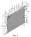
- the tensioner 50 is used in connection with a door assembly, generally referred to by the numeral 10, that includes a framework 11 made up of a header 12 and a pair of jambs 13, 14, having vertical guides 16, 17, which receive door D, mounted thereon.
- This framework 11 defines an opening in which the door D is selectively moved from a closed position depicted in Fig. 1 to an open position (not shown) where the door D is fully retracted and coiled about a plurality of drum wheels 15 located adjacent the header 12 of door D.
- the drum wheels 15 are attached to an axle 20 rotatably supported adjacent header 12 in a position above the opening.
- the door D may be constructed of a plurality of panels 21 including a top panel 22 and a bottom panel 23.
- a bottom bar 24 may be attached to the bottom panel 23 to protect the bottom panel 23 against impact with a floor or objects interposed between the door D and the floor.
- the bottom bar 24 may be formed with a ridge handle, or other member (not shown) that is easily grasped to raise and lower the door D.
- the door D is suitably attached to the drum wheels 15 such that upon opening the door D, the door panels 21 are sequentially coiled around the drum wheels 15 to store the door D in a compact fashion above the opening.
- one or more counterbalance assemblies may be employed to offset the weight of the door D.
- the counterbalance assembly 25 may include a spring 26 constructed of suitable resilient material such as steel, for applying a torsional force to the door D. As shown, spring 26 may be a coil spring located generally coaxially of and surrounding axle 20.
- Spring 26 is attached at its first end 32 to a retainer which may be in the form of an aperture 36 in spring holder 33 and at its second end 31 to one of the drum wheels 15 or axle 20, directly or by clips or fasteners.
- the ends 31, 32 of spring 26, spring holder 33 or drum wheel 15 may be rotatable about axle 20 such that one end of spring 26 is attached to the axle 20 and the other attached to the drum wheel 15 or spring holder 33 such that tension is applied to the spring 26 by rotating the one end relative to the end attached to the drum wheel 15 or spring holder 33, as by turning axle 20. In this way, relative rotation of the ends 31, 32 of spring 26 may be used to develop or release the torsional forces imposed by spring 26.
- spring holder 33 To allow spring holder 33 to rotate relative to the drum wheel 15, spring holder 33 is supported on a sleeve 34 having a bore sized to fit over the axle 20.
- the sleeve 34 may be of greater dimension than axle 20 to accommodate a bearing 38, such as an oil-impregnated collar, fitted within sleeve 33 to journal axle 20, thereby reducing wear or friction.
- Support bracket 40 includes a mounting flange 41 suitably attached to the framework 11, or other supporting structure as by cap screws, and an axle supporting portion 42 projecting rearwardly of the frame 11.
- Axle supporting portion 42 has an opening 43, receiving sleeve 34 and axle 20.
- the opening 43 is sized such that sleeve 34 is free to rotate therein.
- a portion of sleeve 34 may protrude axially outward of support bracket 40 to receive a tool used to rotate sleeve 34, as described below.
- axle 20 may extend beyond sleeve 34 and be axially fixed by a pin 39 that abuts the edge of sleeve 34.
- sleeve 34 may be provided with an annular plate or washer (Fig. 2) adjacent the pin.
- spacing assembly 45 may be placed between the spring holder 33 and bracket assembly 40.
- spacing assembly 45 may include a plurality of tabs 46 that extend axially inward from the axle supporting portion 42 of bracket assembly 40.
- tabs 46 may be placed in circumferentially spaced relation around opening 43.
- three tabs 46 may be arranged in a triangular pattern to act as a stop for axial movement of the spring holder 33.
- one or more members may be used to perform the same function, such as a single annular ridge, or multiple members that extend from support portion 42.
- the tabs 46 are preferably radially spaced away from opening 43 to provide radial clearance for the sleeve 34 to avoid interference of tabs 46 with the free rotation of sleeve 34.
- Tabs 46 may be punched from the axle supporting portion 42 of bracket assembly 40 and constructed to provide minimal contact with spring holder 33. As best shown in Figs. 5 and 6, tabs 46 may be provided with rounded ends 47 to reduce any frictional forces that might develop in the event of contact between the tabs 46 and spring holder 33.
- spring holder 33 may be rotated to adjust the counterbalancing force generated by spring 26.
- spring holder 33 may be rotated with a wrench or rods in a manner known to those of ordinary skill in the art.
- a hex plate 49 or other grippable surface may be attached to the sleeve 34.
- a tensioner assembly is provided or interrelates with the sleeve 34 and spring holder 33 to adjust and maintain the tension of spring 26.
- the tensioner assembly 50 includes a gear wheel 51 supported on sleeve 34 and rotatable therewith.
- a suitable spacer 52 such as a washer, may be located between gear wheel 51 and bracket assembly 40. Spacer 52 may aid in reducing friction between the bracket assembly 40 and gear wheel 51 and further reduce the likelihood of interference between these two members.
- Gear wheel 51 includes a plurality of radially projecting teeth 53 that define notches 54 therebetween. Teeth 53 interrelate with a pawl assembly, generally indicated by the numeral 55, to incrementally lock the position of spring holder 33 against the uncoiling force of spring 26. While the gear wheel 51 is shown with eight teeth 53, the number of teeth 53 may be increased or decreased depending on a desired tensioning increment. The tensioning increment, in terms of one revolution of gear 51, is essentially inversely proportional to the number of teeth 53. In the embodiment shown, the eight (8) teeth result in a tensioning increment of 1/8 of a revolution. Pawl assembly 55 interacts with the teeth 53 and notches 54 to selectively hold the gear wheel 51 against the uncoiling force of spring 26.
- Pawl assembly 55 includes a pawl 56 pivotally mounted to the axle supporting portion 42 of bracket assembly 40, as by a bolt 57 and nut 57'.
- Pawl 56 may be located on support bracket 40 such that its pivot is offset from a center line of axle 20 and the circumference traced by teeth 53. In this circumstance, pawl 56 may extend from pivot 57 at an acute angle from a horizontal line passing through the center of the pivot 57. If pawl 56 is curved, as shown, the angle of pawl 56 would vary with the increasing slope of the interior surface 72 of pawl 56.
- suitable spacers 58 such as washers may be used to insure proper axial alignment of the pawl 56 and teeth 53.
- the interaction of the pawl 56 with teeth 53 to lock the position of spring holder 33 causes the tensioning increment to act as a lower limit on the amount of adjustment the installer may make in tensioning spring 26.
- the pawl 56 may be biased into an engaged position with gear 51, as shown in solid lines in Fig.4.
- the pawl 56 may be biased by gravity or a biasing assembly, generally indicated by the numeral 60, which includes a biasing member, such as spring 61.
- spring 61 exerts an upward force on pawl 56 to drive it into an engaged position (solid lines) by means of opposed first and second legs 62, 63 extending from a wound vertex 64.
- the spring 61 may be axially located by bolt 57, which forms a pivot for pawl 56.
- the shank of bolt 57 is sized to fit through wound vertex 64 and into a bore formed in pawl 56.
- Bolt 57 may be secured to support bracket 40, as by the nut 57'. Once secured, the head of bolt 57 traps vertex 64 against pawl 56.
- the extending legs 62, 63 of spring 61 are compressed between a pair of projections 65, 66.
- Projections 65, 66 extend axially outward from pawl 56 and the axle supporting portion 42 of bracket assembly 40, respectively. Projections 65, 66 may be formed on their respective members, fastened thereto, or formed by fasteners, such as caps screws 67, 68.
- Projections 65, 66 in general, may be of any configuration shape, or size suitable for capturing the ends of biasing member 61. As shown, cap screws 67, 68, which form projections 65, 66, extend a sufficient distance such that they may provide fingerholds for manual or tool-assisted actuation of the pawl 56, as described below.
- the installer may squeeze first projection 65 toward second projection 66 to urge the pawl 56 toward a disengaged position, shown in broken lines in Fig. 4, where the pawl has cleared the adjacent tooth 53.
- the gear 51 is free to rotate.
- the installer may adjust the tension on spring 26 by rotating spring holder 33 in the appropriate direction.
- the pawl 56 may be released allowing bias assembly 60 to return the pawl 56 to the solid line engaged position.
- Each tooth 53 of gear 51 is provided with a stop face 70 that engages the pawl 56.
- the stop face 70 is disposed such that it interrelates with the pawl 56 in reaching a state of equilibrium, when the pawl 56 is engaged.
- rotation of gear 51 in a direction that moves the stop face 70 away from pawl 56 in this case a clockwise rotation, may be used to periodically displace pawl 56 out of engagement with the passage of each tooth 53.
- a run face 71 connects successive stop faces 70 providing a surface along which the pawl 56 rides during rotation of gear wheel 51.
- run face 71 and stop face 70 join each other at a vertex 73, and, from this point, run face 71 slopes radially outward and away from stop face 70. Run face 71 reaches a peak 74 corresponding to the radial height of stop face 70. In this way the interior surface 72 of pawl 56 rides along run surface 71 in a cam-follower fashion. The slope of run face 71 displaces pawl 56 radially outward of its contact position against stop face 70 to remove the pawl 56 from the engaged position and prepare the pawl for the successive locking motion, where the pawl 56, under the urging of biasing assembly 60, is driven into the next notch 54.
- This locking motion may be characterized by an audible "click", as the pawl 56 is snapped into place, informing the installer that the pawl 56 has attained the engaged position and that the gear wheel 51 has traveled one tensioning increment.
- the run face 71 of gear 51 and interior surface 72 of pawl 56 are made nonlinear or arcuate such that pawl 56 extends in an arcuate fashion toward teeth 53.
- the profile of interior surface 72 of pawl 56 may generally correspond to the run face 71 to provide smoother interrelation of the pawl 56 and gear wheel 51. As shown, these surfaces 71, 72 may be elongated to gradually move the pawl 56 out of engagement with the stop surface 70 of tooth 53 as the gear wheel 51 is rotated.
- run face 71 may initially extend in a non-linear fashion, which may be exponential, through a varying angle a toward the peak 74 of tooth 53.
- Stop face 70 may radially extend inward from peak 74 such that it is disposed generally perpendicular to the pawl 56 upon contact.
- the stop face 70 may extend inwardly from peak 74 toward a radial line R extending through the vertex 73 to create an acute angle between the adjacent run face 71.
- stop face 70 is "undercut", signifying that stop face 70 is disposed at an acute angle ⁇ relative to radial line R.
- the undercut stop face 70 helps to draw the pawl 56 radially inward as the gear wheel 51 rotates.
- gear wheel 51 may have a number of teeth 53 that provide separate points of adjustment for the counterbalance assembly 25.
- the embodiment depicted has eight teeth 53 allowing the gear wheel 51 or spring holder 33 to be rotated in one-eighth increments of a complete rotation. As will be appreciated, fewer teeth 53 may be used for coarser incrementation and additional teeth 53 may be added to provide finer adjustment of the counterbalancing force.
- a locking assembly may be used to prevent the spring holder 33 from rotating.
- either of the gear wheel 51 or pawl 56 may be locked in place by locking assembly 65, such that gear wheel 51 and connected spring holder 33 are not free to rotate.
- Locking assembly 65 may include a lock member that is not easily removed to guard against a user from pulling the member out by hand or having the member come free when jarred or under the influence of vibration within the structure.
- Suitable lock members might include a Zip-tie or similar device or a fastener, such as a cap screw 67 may be inserted through pawl 56 and into bracket assembly 40 to prevent the pawl 56 from moving out of the engaged position. In that way, the installer may secure the cap screw 67 into a threaded bore 68 in support bracket 40 or a nut, such that an average person would not be able to accidentally remove the cap screw 67 or otherwise release gear 51. This helps eliminate accidental release of the counterbalance assembly 25 and discourages tampering with the tensioning assembly 50. In operation, tensioner 50 automatically retains the position of spring holder 33 and accordingly tension on counterbalance assembly 25 by biasing pawl assembly 55 into locking engagement with gear wheel 51.
- a fastener such as a cap screw 67 may be inserted through pawl 56 and into bracket assembly 40 to prevent the pawl 56 from moving out of the engaged position. In that way, the installer may secure the cap screw 67 into a threaded bore 68 in support bracket 40
- the device 50 may be assembled as shown in Fig. 6 with the gear wheel 51 and spring holder 33 located on opposite sides of support bracket 40.
- the counterbalance spring 26 of door assembly 10 is attached to the spring holder 33, as by a nut and bolt.
- the user would apply a force to hex plate 49 or sleeve 34 using pliers, a pipe wrench, or rods, which may be inserted through sleeve 34 or other tools known in the art.
- the gear wheel 51 of tensioner assembly 50 would rotate past pawl assembly 55.
- Pawl 56 of pawl assembly 55 would follow the contour of gear wheel 51 in a cam follower-type fashion.
- the installer may lock tensioner 50 with a locking assembly, such as by driving cap screw 67 into support bracket 40 to lock the pawl 56 in place to prevent tampering with the tensioner 50.
Landscapes
- Engineering & Computer Science (AREA)
- Structural Engineering (AREA)
- Architecture (AREA)
- Civil Engineering (AREA)
- Closing And Opening Devices For Wings, And Checks For Wings (AREA)
- Power-Operated Mechanisms For Wings (AREA)
- Rolls And Other Rotary Bodies (AREA)
- Unwinding Webs (AREA)
Claims (16)
- Toranordnung für ein aus mehreren Segmenten bestehendes Tor (D), die so eingerichtet ist, dass sie relativ zu einer Achse selektiv nach oben und nach unten bewegt werden kann, wobei die Anordnung eine Achse (20), die von Endträgern getragen wird, eine Zugeinrichtung, die mit der Achse verbunden ist, eine Drehfeder (26) mit einem ersten Ende zur funktionalen Anbringung an dem aus mehreren Segmenten bestehenden Tor und einem zweiten Ende, das funktionell an der Zugeinrichtung angebracht ist, dadurch gekennzeichnet, dass die Zugeinrichtung ein Zahnrad (51) mit einer Vielzahl von Zähnen enthält, wobei die Zähne eine unterschnittene Anschlagfläche (70) und eine bogenförmige Lauffläche (71) aufweisen, die zwischen den Anschlagflächen benachbarter Zähne angeordnet ist, sowie eine schwenkbar angebrachte Klinke (56), die selektiv mit der Anschlagfläche (70) in Eingriff kommt, um eine ausgewählte Ausgleichskrafteinstellung aufrechtzuerhalten.
- Toranordnung nach Anspruch 1, wobei die Zähne eine Spitze an einem Ende der unterschnittenen Anschlagfläche und einen Scheitelpunkt an einem anderen Ende haben, so dass eine Einkerbung entsteht, wobei die bogenförmige Lauffläche die Klinke selektiv auf der Einkerbung verschiebt.
- Rolltoranordnung nach Anspruch 1 oder 2, wobei sich die Lauffläche von dem Scheitelpunkt nichtlinear zu der Spitze erstreckt.
- Toranordnung nach Anspruch 1, 2 oder 3, wobei die Klinke eine nichtlineare radiale Innenfläche hat, die im Wesentlichen der Lauffläche entspricht.
- Toranordnung nach einem der vorangehenden Ansprüche, die des Weiteren ein Spannelement enthält, das die Klinke (56) auf die Eingriffsposition zu drückt.
- Toranordnung nach einem der vorangehenden Ansprüche, wobei die Klinke (56) schwenkbar an einem Träger (40) angebracht ist.
- Toranordnung nach den Ansprüchen 5 oder 6, die des Weiteren einen ersten Vorsprung (65), der sich von der Klinke (56) aus erstreckt, und einen zweiten Vorsprung (66) umfasst, der sich von dem Träger aus erstreckt, wobei der zweite Vorzu der Klinke stationär ist und das Spannelement auf die Vorsprünge wirkt, um die Klinke in die Eingriffsposition zu drücken.
- Toranordnung nach Anspruch 7, wobei das Spannelement eine Feder ist.
- Toranordnung nach Anspruch 8, wobei die Klinke an dem Träger (40) an einer Drehachse angebracht ist, die Feder einen stationären Scheitelpunkt (64) sowie einen ersten Schenkel (62) und einen zweiten Schenkel (63) hat, die sich von dem Scheitelpunkt aus erstrecken, wobei der erste und der zweite Schenkel zwischen den Vorsprüngen zusammengedrückt werden, um die Klinke (56) auf die Eingriffsposition zuzudrücken.
- Toranordnung nach Anspruch 9, wobei der Scheitelpunkt (64) koaxial zu der Drehachse (57) angeordnet ist.
- Toranordnung nach Anspruch 10, die des Weiteren ein Arretierelement (67) umfasst, das die Klinke (56) selektiv an dem Träger (40) anbringt, um die Klinke in der Eingriffsposition zu arretieren.
- Toranordnung nach Anspruch 11, wobei das Arretierelement ein Befestigungselement (67) enthält, mit dem die Klinke an dem Träger angebracht ist.
- Toranordnung nach Anspruch 12, wobei das Befestigungselement (67) an der Klinke (56) getragen wird, so dass das Befestigungselement selektiv in den Träger hinein bewegt wird, um die Klinke daran zu arretieren.
- Toranordnung nach einem der vorangehenden Ansprüche, wobei das Zahnrad (51) an einer Hülse (34) angebracht ist, die auf der Achse montiert ist, und ein Haltelement (4) für die Drehfeder enthält, die sich an einem Federhalter befindet.
- Toranordnung nach Anspruch 14, wobei sich die Hülse (34) durch eine Bohrung (43) in einem der Endträger erstreckt und einer der Endträger zwischen dem Zahnrad und dem Federhalter angeordnet ist.
- Aus mehreren Segmenten bestehendes Tor mit einer Toranordnung nach einem der vorangehenden Ansprüche.
Applications Claiming Priority (3)
| Application Number | Priority Date | Filing Date | Title |
|---|---|---|---|
| US858787 | 2001-05-16 | ||
| US09/858,787 US6527037B2 (en) | 2001-05-16 | 2001-05-16 | Rolling door tensioner |
| PCT/US2002/014818 WO2002092950A1 (en) | 2001-05-16 | 2002-05-09 | Rolling door tensioner |
Publications (2)
| Publication Number | Publication Date |
|---|---|
| EP1387922A1 EP1387922A1 (de) | 2004-02-11 |
| EP1387922B1 true EP1387922B1 (de) | 2007-05-02 |
Family
ID=25329180
Family Applications (1)
| Application Number | Title | Priority Date | Filing Date |
|---|---|---|---|
| EP02734344A Expired - Lifetime EP1387922B1 (de) | 2001-05-16 | 2002-05-09 | Spannvorrichtung für ein rolltor |
Country Status (7)
| Country | Link |
|---|---|
| US (1) | US6527037B2 (de) |
| EP (1) | EP1387922B1 (de) |
| AT (1) | ATE361409T1 (de) |
| AU (1) | AU2002305518B2 (de) |
| CA (1) | CA2444799C (de) |
| DE (1) | DE60219908T2 (de) |
| WO (1) | WO2002092950A1 (de) |
Families Citing this family (45)
| Publication number | Priority date | Publication date | Assignee | Title |
|---|---|---|---|---|
| US6672691B1 (en) * | 2001-04-27 | 2004-01-06 | David A. Hoff | Control mechanism for tambour-style door closures |
| US7144051B2 (en) * | 2001-08-08 | 2006-12-05 | The Chamberlain Group, Inc. | Method and apparatus for providing for fail safe condition for an automatic security gate |
| CA2400541A1 (en) * | 2001-08-31 | 2003-02-28 | William English | Positional control device for sectional doors |
| US6644378B2 (en) | 2001-11-02 | 2003-11-11 | Wayne-Dalton Corp. | Tensioning device for a door system |
| US7156595B2 (en) * | 2001-11-16 | 2007-01-02 | Clarke Ronald C | Load indicating fastener insert |
| US7543625B2 (en) * | 2002-03-19 | 2009-06-09 | Canimex Inc. | Brake device for garage doors and the like, and door assembly including the same |
| WO2003078773A1 (en) * | 2002-03-19 | 2003-09-25 | Canimex Inc. | Safety braking device for counterbalancing system of garage doors and the like |
| US20040020609A1 (en) * | 2002-04-10 | 2004-02-05 | Canimex Inc. | Ratchet-like system for winding a rolling door assembly |
| US20070012410A1 (en) * | 2002-04-10 | 2007-01-18 | Canimex Inc. | Ratchet system for winding a rolling door assembly |
| US7686061B2 (en) * | 2002-04-24 | 2010-03-30 | Overhead Door Corporation | Winding assembly for door counterbalance system |
| US6896027B2 (en) * | 2003-07-15 | 2005-05-24 | Nci Building Systems, L.P. | Method and apparatus for suspending a door |
| US7207370B2 (en) * | 2004-03-25 | 2007-04-24 | Rite-Hite Holding Corporation | Retractable safety barrier |
| US8547234B2 (en) | 2004-12-14 | 2013-10-01 | Rite-Hite Holding Corporation | Alarm system for a loading dock |
| US8590087B2 (en) * | 2004-12-14 | 2013-11-26 | Rite-Hite Holding Corporation | Lighting and signaling systems for loading docks |
| US7380375B2 (en) * | 2004-12-14 | 2008-06-03 | Rite-Hite Holding Corporation | Alarm system for a loading dock |
| US7254868B2 (en) * | 2004-12-27 | 2007-08-14 | Wayne-Dalton Corp. | winding and anti-drop assembly for door counterbalance system |
| EP1764473B1 (de) * | 2005-09-15 | 2010-09-01 | Cardo Entrance Solutions AB | Federspannung |
| ES2341969T3 (es) * | 2005-09-15 | 2010-06-30 | Cardo Entrance Solutions Ab | Ajuste de la tension de un muelle. |
| US20070204515A1 (en) * | 2006-02-06 | 2007-09-06 | Canimex Inc. | Brake device for garage doors and the like, kit for assembling the same, and door assembly provided with the brake device |
| US8925617B2 (en) * | 2006-06-01 | 2015-01-06 | Qualitas Manaufacturing, Inc. | Shutter slat end retention system |
| US8616261B2 (en) * | 2006-06-01 | 2013-12-31 | Qualitas Manufacturing Inc. | Shutter slat end retention system |
| CA2659737A1 (en) * | 2006-08-01 | 2008-02-07 | Ad-Tech, Llc | Roll-up retractable sheet device |
| DE102006042637B4 (de) * | 2006-09-01 | 2008-09-25 | Getrag Getriebe- Und Zahnradfabrik Hermann Hagenmeyer Gmbh & Cie Kg | Parksperrenanordnung |
| US7637031B2 (en) * | 2007-06-26 | 2009-12-29 | Gm Global Technology Operations, Inc. | Evaporator core drying system |
| MX2009014082A (es) | 2007-07-06 | 2010-03-01 | Rite Hite Holding Corp | Barreras de seguridad retráctiles y sus métodos de operación. |
| CA2629679C (en) * | 2008-04-24 | 2015-07-14 | Mike Svenson | Roll-up closure |
| US8397787B1 (en) * | 2009-04-20 | 2013-03-19 | Overhead Door Corporation | Door release mechanism |
| US8375635B2 (en) * | 2009-08-26 | 2013-02-19 | Richard Hellinga | Apparatus for opening and closing overhead sectional doors |
| US8616093B1 (en) | 2009-09-01 | 2013-12-31 | David Maniak | Torsion spring torque assembly |
| US8608126B2 (en) * | 2011-03-07 | 2013-12-17 | Philip Ng | Vibration isolation brackets for roller blinds |
| CA2897206C (en) * | 2014-01-31 | 2017-06-13 | Yannick Funk | Winding ratchet system for counterbalancing system |
| US20170191293A1 (en) * | 2015-12-30 | 2017-07-06 | Sos Systems, Llc | Door security device |
| US11261661B2 (en) | 2018-10-16 | 2022-03-01 | Mechoshade Systems, Llc | Roller shade system |
| US12281520B2 (en) | 2018-10-16 | 2025-04-22 | Mechoshade Systems, Llc | Friction slip ring for a drive mechanism |
| CN117418493A (zh) | 2019-08-21 | 2024-01-19 | 瑞泰控股公司 | 抗冲击的可伸缩安全屏障 |
| USD1019986S1 (en) * | 2021-11-20 | 2024-03-26 | Dongguan Geshengmei Industrial Co., Ltd. | Rolling door |
| USD1019987S1 (en) * | 2022-01-10 | 2024-03-26 | Dongguan Geshengmei Industrial Co., Ltd. | Rolling door |
| TWI790954B (zh) * | 2022-03-29 | 2023-01-21 | 謝仲賢 | 分段式升降門系統 |
| USD1017073S1 (en) * | 2022-05-10 | 2024-03-05 | Honglin Wei | Shutter door |
| US20240200403A1 (en) * | 2022-12-20 | 2024-06-20 | Snl Steel Llc | Rollup door tension device |
| USD999935S1 (en) * | 2023-02-28 | 2023-09-26 | Honglin Wei | Shutter door |
| USD999936S1 (en) * | 2023-03-06 | 2023-09-26 | Honglin Wei | Shutter door |
| PL447765A1 (pl) * | 2024-02-14 | 2025-08-18 | Fakro Pp Spółka Z Ograniczoną Odpowiedzialnością | Zespół nakręcania sprężyny mechanizmu wspomagającego prowadzenie materiału zasłaniającego zasłony przegrody budowlanej oraz zasłona przegrody budowlanej z tym zespołem |
| US12560278B2 (en) * | 2024-05-24 | 2026-02-24 | Rob J Evans | Torsion spring bracing system and method for installation thereof |
| US12480345B1 (en) * | 2025-08-15 | 2025-11-25 | Cltc Llc | Integrated bracket assembly with head stop for overhead doors |
Family Cites Families (19)
| Publication number | Priority date | Publication date | Assignee | Title |
|---|---|---|---|---|
| US575572A (en) * | 1897-01-19 | George mulford parsons | ||
| US842936A (en) * | 1906-05-23 | 1907-02-05 | Charles B Case | Window-shade roller. |
| US1994142A (en) | 1930-04-24 | 1935-03-12 | Yoder Morris Company | Door operating mechanism |
| US2097242A (en) | 1934-04-30 | 1937-10-26 | Stanley Works | Articulated overhead door |
| US3734161A (en) | 1970-08-26 | 1973-05-22 | E Pierce | Door construction |
| US3672492A (en) * | 1971-02-09 | 1972-06-27 | North American Door Corp | Factory-assembled overhead door |
| US4356668A (en) | 1980-10-20 | 1982-11-02 | Wagner Richard P | Method and apparatus for door protection |
| US4583706A (en) * | 1981-07-10 | 1986-04-22 | Byrne & Davidson Doors (N.S.W.) Pty. Limited | Mounting and stowing arrangements for rolling doors |
| US4472910A (en) | 1982-09-29 | 1984-09-25 | Chamnberlain Manufacturing Corporation | Integral device for garage door opener |
| US4597224A (en) | 1984-02-02 | 1986-07-01 | Tucker Derry E | Automatic garage door opener |
| US4817927A (en) | 1986-08-21 | 1989-04-04 | Martin Door Manufacturing | Coil torsion spring mounting cones with groove break and method of mounting |
| US4981165A (en) | 1989-04-11 | 1991-01-01 | Millco Products, Inc. | Spring adjustment device for overhead doors |
| US4930182A (en) | 1989-04-14 | 1990-06-05 | Apco Power-Unit Corporation | Apparatus for counterbalancing an overhead door |
| US5222327A (en) | 1991-07-22 | 1993-06-29 | Fellows Donna M | Side mount garage door operator |
| US5239777A (en) | 1992-03-24 | 1993-08-31 | Atlas Roll-Lite Door Corporation | Overhead door pre-loaded and pre-assembled torsion spring counterbalance assembly |
| US5253693A (en) * | 1992-09-29 | 1993-10-19 | Atlas Roll-Lite Door Corp. | Hold and release mechanism for a fire door spring tension adjusting wheel |
| US5778490A (en) | 1996-01-24 | 1998-07-14 | Curtis; David B. | Tension device for live axle doors |
| US6155327A (en) | 1999-06-03 | 2000-12-05 | Overhead Door Corporation | Counterbalance system adjustment mechanism for rollup door |
| US6283193B1 (en) * | 1999-07-06 | 2001-09-04 | Harry E. Finch | Adjustable tensioning arrangement for modular security door system |
-
2001
- 2001-05-16 US US09/858,787 patent/US6527037B2/en not_active Expired - Lifetime
-
2002
- 2002-05-09 WO PCT/US2002/014818 patent/WO2002092950A1/en not_active Ceased
- 2002-05-09 CA CA002444799A patent/CA2444799C/en not_active Expired - Fee Related
- 2002-05-09 DE DE60219908T patent/DE60219908T2/de not_active Expired - Fee Related
- 2002-05-09 AT AT02734344T patent/ATE361409T1/de not_active IP Right Cessation
- 2002-05-09 EP EP02734344A patent/EP1387922B1/de not_active Expired - Lifetime
- 2002-05-09 AU AU2002305518A patent/AU2002305518B2/en not_active Ceased
Non-Patent Citations (1)
| Title |
|---|
| None * |
Also Published As
| Publication number | Publication date |
|---|---|
| CA2444799A1 (en) | 2002-11-21 |
| US20020170688A1 (en) | 2002-11-21 |
| WO2002092950A1 (en) | 2002-11-21 |
| US6527037B2 (en) | 2003-03-04 |
| ATE361409T1 (de) | 2007-05-15 |
| DE60219908D1 (de) | 2007-06-14 |
| AU2002305518B2 (en) | 2007-05-24 |
| DE60219908T2 (de) | 2008-01-17 |
| CA2444799C (en) | 2009-10-13 |
| EP1387922A1 (de) | 2004-02-11 |
Similar Documents
| Publication | Publication Date | Title |
|---|---|---|
| EP1387922B1 (de) | Spannvorrichtung für ein rolltor | |
| AU2002305518A1 (en) | Rolling door tensioner | |
| US7686061B2 (en) | Winding assembly for door counterbalance system | |
| US7254868B2 (en) | winding and anti-drop assembly for door counterbalance system | |
| US4583262A (en) | Spring hinge | |
| US6640496B2 (en) | Anti-drop device | |
| US5605079A (en) | Torsion spring tensioning tool | |
| US20030230389A1 (en) | Winding system, rolling door assembly including the same and kit for assembling the winding system | |
| US6644378B2 (en) | Tensioning device for a door system | |
| US20110240236A1 (en) | Ratchet system for winding a rolling door assembly | |
| EP2589742B1 (de) | Vorrichtung zur Sicherung von Rolläden und Rolltoren | |
| US6907964B2 (en) | Ratchet-like assembly for winding a counterbalancing mechanism of a door, door assembly including the same and kit for assembling the ratchet-like assembly | |
| DE602004001511T2 (de) | Kabelversagensvorrichtung für garagentore und dergleichen sowie diese enthaltende tür | |
| US20040020609A1 (en) | Ratchet-like system for winding a rolling door assembly | |
| US4603461A (en) | Garage door spring stretcher | |
| US20240026720A1 (en) | Winding device and methods | |
| CA2441040C (en) | Torsion spring tensioning apparatus | |
| CA2435362A1 (en) | Ratchet assembly for winding a counterbalancing mechanism of a door, door assembly including the same and kit for assembling the ratchet assembly | |
| CA2426068C (en) | Winding system, rolling door assembly including the same and kit for assembling the winding system | |
| AU2021373059A1 (en) | A winding device | |
| CA3023650A1 (en) | Shaft clamp | |
| CA2425108A1 (en) | Rachet system for winding a rolling door assembly |
Legal Events
| Date | Code | Title | Description |
|---|---|---|---|
| PUAI | Public reference made under article 153(3) epc to a published international application that has entered the european phase |
Free format text: ORIGINAL CODE: 0009012 |
|
| 17P | Request for examination filed |
Effective date: 20031021 |
|
| AK | Designated contracting states |
Kind code of ref document: A1 Designated state(s): AT BE CH CY DE DK ES FI FR GB GR IE IT LI LU MC NL PT SE TR |
|
| GRAP | Despatch of communication of intention to grant a patent |
Free format text: ORIGINAL CODE: EPIDOSNIGR1 |
|
| GRAS | Grant fee paid |
Free format text: ORIGINAL CODE: EPIDOSNIGR3 |
|
| GRAA | (expected) grant |
Free format text: ORIGINAL CODE: 0009210 |
|
| AK | Designated contracting states |
Kind code of ref document: B1 Designated state(s): AT BE CH CY DE DK ES FI FR GB GR IE IT LI LU MC NL PT SE TR |
|
| PG25 | Lapsed in a contracting state [announced via postgrant information from national office to epo] |
Ref country code: FI Free format text: LAPSE BECAUSE OF FAILURE TO SUBMIT A TRANSLATION OF THE DESCRIPTION OR TO PAY THE FEE WITHIN THE PRESCRIBED TIME-LIMIT Effective date: 20070502 Ref country code: LI Free format text: LAPSE BECAUSE OF FAILURE TO SUBMIT A TRANSLATION OF THE DESCRIPTION OR TO PAY THE FEE WITHIN THE PRESCRIBED TIME-LIMIT Effective date: 20070502 Ref country code: CH Free format text: LAPSE BECAUSE OF FAILURE TO SUBMIT A TRANSLATION OF THE DESCRIPTION OR TO PAY THE FEE WITHIN THE PRESCRIBED TIME-LIMIT Effective date: 20070502 |
|
| REG | Reference to a national code |
Ref country code: GB Ref legal event code: FG4D |
|
| REG | Reference to a national code |
Ref country code: CH Ref legal event code: EP |
|
| REG | Reference to a national code |
Ref country code: IE Ref legal event code: FG4D |
|
| REF | Corresponds to: |
Ref document number: 60219908 Country of ref document: DE Date of ref document: 20070614 Kind code of ref document: P |
|
| PG25 | Lapsed in a contracting state [announced via postgrant information from national office to epo] |
Ref country code: SE Free format text: LAPSE BECAUSE OF FAILURE TO SUBMIT A TRANSLATION OF THE DESCRIPTION OR TO PAY THE FEE WITHIN THE PRESCRIBED TIME-LIMIT Effective date: 20070802 |
|
| PG25 | Lapsed in a contracting state [announced via postgrant information from national office to epo] |
Ref country code: ES Free format text: LAPSE BECAUSE OF FAILURE TO SUBMIT A TRANSLATION OF THE DESCRIPTION OR TO PAY THE FEE WITHIN THE PRESCRIBED TIME-LIMIT Effective date: 20070813 |
|
| ET | Fr: translation filed | ||
| NLV1 | Nl: lapsed or annulled due to failure to fulfill the requirements of art. 29p and 29m of the patents act | ||
| REG | Reference to a national code |
Ref country code: CH Ref legal event code: PL |
|
| PG25 | Lapsed in a contracting state [announced via postgrant information from national office to epo] |
Ref country code: AT Free format text: LAPSE BECAUSE OF FAILURE TO SUBMIT A TRANSLATION OF THE DESCRIPTION OR TO PAY THE FEE WITHIN THE PRESCRIBED TIME-LIMIT Effective date: 20070502 |
|
| PG25 | Lapsed in a contracting state [announced via postgrant information from national office to epo] |
Ref country code: BE Free format text: LAPSE BECAUSE OF FAILURE TO SUBMIT A TRANSLATION OF THE DESCRIPTION OR TO PAY THE FEE WITHIN THE PRESCRIBED TIME-LIMIT Effective date: 20070502 |
|
| PG25 | Lapsed in a contracting state [announced via postgrant information from national office to epo] |
Ref country code: NL Free format text: LAPSE BECAUSE OF FAILURE TO SUBMIT A TRANSLATION OF THE DESCRIPTION OR TO PAY THE FEE WITHIN THE PRESCRIBED TIME-LIMIT Effective date: 20070502 Ref country code: DK Free format text: LAPSE BECAUSE OF FAILURE TO SUBMIT A TRANSLATION OF THE DESCRIPTION OR TO PAY THE FEE WITHIN THE PRESCRIBED TIME-LIMIT Effective date: 20070502 Ref country code: PT Free format text: LAPSE BECAUSE OF FAILURE TO SUBMIT A TRANSLATION OF THE DESCRIPTION OR TO PAY THE FEE WITHIN THE PRESCRIBED TIME-LIMIT Effective date: 20071002 Ref country code: MC Free format text: LAPSE BECAUSE OF NON-PAYMENT OF DUE FEES Effective date: 20070531 |
|
| PLBE | No opposition filed within time limit |
Free format text: ORIGINAL CODE: 0009261 |
|
| STAA | Information on the status of an ep patent application or granted ep patent |
Free format text: STATUS: NO OPPOSITION FILED WITHIN TIME LIMIT |
|
| 26N | No opposition filed |
Effective date: 20080205 |
|
| PG25 | Lapsed in a contracting state [announced via postgrant information from national office to epo] |
Ref country code: IT Free format text: LAPSE BECAUSE OF FAILURE TO SUBMIT A TRANSLATION OF THE DESCRIPTION OR TO PAY THE FEE WITHIN THE PRESCRIBED TIME-LIMIT Effective date: 20070502 Ref country code: GR Free format text: LAPSE BECAUSE OF FAILURE TO SUBMIT A TRANSLATION OF THE DESCRIPTION OR TO PAY THE FEE WITHIN THE PRESCRIBED TIME-LIMIT Effective date: 20070803 |
|
| PG25 | Lapsed in a contracting state [announced via postgrant information from national office to epo] |
Ref country code: IE Free format text: LAPSE BECAUSE OF NON-PAYMENT OF DUE FEES Effective date: 20070509 |
|
| PGFP | Annual fee paid to national office [announced via postgrant information from national office to epo] |
Ref country code: DE Payment date: 20080515 Year of fee payment: 7 |
|
| PGFP | Annual fee paid to national office [announced via postgrant information from national office to epo] |
Ref country code: GB Payment date: 20080514 Year of fee payment: 7 |
|
| PG25 | Lapsed in a contracting state [announced via postgrant information from national office to epo] |
Ref country code: CY Free format text: LAPSE BECAUSE OF FAILURE TO SUBMIT A TRANSLATION OF THE DESCRIPTION OR TO PAY THE FEE WITHIN THE PRESCRIBED TIME-LIMIT Effective date: 20070502 |
|
| PG25 | Lapsed in a contracting state [announced via postgrant information from national office to epo] |
Ref country code: LU Free format text: LAPSE BECAUSE OF NON-PAYMENT OF DUE FEES Effective date: 20070509 |
|
| PG25 | Lapsed in a contracting state [announced via postgrant information from national office to epo] |
Ref country code: TR Free format text: LAPSE BECAUSE OF FAILURE TO SUBMIT A TRANSLATION OF THE DESCRIPTION OR TO PAY THE FEE WITHIN THE PRESCRIBED TIME-LIMIT Effective date: 20070502 |
|
| GBPC | Gb: european patent ceased through non-payment of renewal fee |
Effective date: 20090509 |
|
| REG | Reference to a national code |
Ref country code: FR Ref legal event code: ST Effective date: 20100129 |
|
| PG25 | Lapsed in a contracting state [announced via postgrant information from national office to epo] |
Ref country code: FR Free format text: LAPSE BECAUSE OF NON-PAYMENT OF DUE FEES Effective date: 20090602 |
|
| PGFP | Annual fee paid to national office [announced via postgrant information from national office to epo] |
Ref country code: FR Payment date: 20080514 Year of fee payment: 7 |
|
| PG25 | Lapsed in a contracting state [announced via postgrant information from national office to epo] |
Ref country code: GB Free format text: LAPSE BECAUSE OF NON-PAYMENT OF DUE FEES Effective date: 20090509 |
|
| PG25 | Lapsed in a contracting state [announced via postgrant information from national office to epo] |
Ref country code: DE Free format text: LAPSE BECAUSE OF NON-PAYMENT OF DUE FEES Effective date: 20091201 |