EP1388450A2 - Dispositif de commande pour véhicule hybride - Google Patents
Dispositif de commande pour véhicule hybride Download PDFInfo
- Publication number
- EP1388450A2 EP1388450A2 EP03017462A EP03017462A EP1388450A2 EP 1388450 A2 EP1388450 A2 EP 1388450A2 EP 03017462 A EP03017462 A EP 03017462A EP 03017462 A EP03017462 A EP 03017462A EP 1388450 A2 EP1388450 A2 EP 1388450A2
- Authority
- EP
- European Patent Office
- Prior art keywords
- engine
- output
- motor
- cylinder deactivation
- torque
- Prior art date
- Legal status (The legal status is an assumption and is not a legal conclusion. Google has not performed a legal analysis and makes no representation as to the accuracy of the status listed.)
- Granted
Links
Images


Classifications
-
- B—PERFORMING OPERATIONS; TRANSPORTING
- B60—VEHICLES IN GENERAL
- B60W—CONJOINT CONTROL OF VEHICLE SUB-UNITS OF DIFFERENT TYPE OR DIFFERENT FUNCTION; CONTROL SYSTEMS SPECIALLY ADAPTED FOR HYBRID VEHICLES; ROAD VEHICLE DRIVE CONTROL SYSTEMS FOR PURPOSES NOT RELATED TO THE CONTROL OF A PARTICULAR SUB-UNIT
- B60W20/00—Control systems specially adapted for hybrid vehicles
-
- B—PERFORMING OPERATIONS; TRANSPORTING
- B60—VEHICLES IN GENERAL
- B60K—ARRANGEMENT OR MOUNTING OF PROPULSION UNITS OR OF TRANSMISSIONS IN VEHICLES; ARRANGEMENT OR MOUNTING OF PLURAL DIVERSE PRIME-MOVERS IN VEHICLES; AUXILIARY DRIVES FOR VEHICLES; INSTRUMENTATION OR DASHBOARDS FOR VEHICLES; ARRANGEMENTS IN CONNECTION WITH COOLING, AIR INTAKE, GAS EXHAUST OR FUEL SUPPLY OF PROPULSION UNITS IN VEHICLES
- B60K6/00—Arrangement or mounting of plural diverse prime-movers for mutual or common propulsion, e.g. hybrid propulsion systems comprising electric motors and internal combustion engines
- B60K6/20—Arrangement or mounting of plural diverse prime-movers for mutual or common propulsion, e.g. hybrid propulsion systems comprising electric motors and internal combustion engines the prime-movers consisting of electric motors and internal combustion engines, e.g. HEVs
- B60K6/42—Arrangement or mounting of plural diverse prime-movers for mutual or common propulsion, e.g. hybrid propulsion systems comprising electric motors and internal combustion engines the prime-movers consisting of electric motors and internal combustion engines, e.g. HEVs characterised by the architecture of the hybrid electric vehicle
- B60K6/48—Parallel type
- B60K6/485—Motor-assist type
-
- B—PERFORMING OPERATIONS; TRANSPORTING
- B60—VEHICLES IN GENERAL
- B60W—CONJOINT CONTROL OF VEHICLE SUB-UNITS OF DIFFERENT TYPE OR DIFFERENT FUNCTION; CONTROL SYSTEMS SPECIALLY ADAPTED FOR HYBRID VEHICLES; ROAD VEHICLE DRIVE CONTROL SYSTEMS FOR PURPOSES NOT RELATED TO THE CONTROL OF A PARTICULAR SUB-UNIT
- B60W10/00—Conjoint control of vehicle sub-units of different type or different function
- B60W10/04—Conjoint control of vehicle sub-units of different type or different function including control of propulsion units
- B60W10/06—Conjoint control of vehicle sub-units of different type or different function including control of propulsion units including control of combustion engines
-
- B—PERFORMING OPERATIONS; TRANSPORTING
- B60—VEHICLES IN GENERAL
- B60W—CONJOINT CONTROL OF VEHICLE SUB-UNITS OF DIFFERENT TYPE OR DIFFERENT FUNCTION; CONTROL SYSTEMS SPECIALLY ADAPTED FOR HYBRID VEHICLES; ROAD VEHICLE DRIVE CONTROL SYSTEMS FOR PURPOSES NOT RELATED TO THE CONTROL OF A PARTICULAR SUB-UNIT
- B60W10/00—Conjoint control of vehicle sub-units of different type or different function
- B60W10/04—Conjoint control of vehicle sub-units of different type or different function including control of propulsion units
- B60W10/08—Conjoint control of vehicle sub-units of different type or different function including control of propulsion units including control of electric propulsion units, e.g. motors or generators
-
- F—MECHANICAL ENGINEERING; LIGHTING; HEATING; WEAPONS; BLASTING
- F02—COMBUSTION ENGINES; HOT-GAS OR COMBUSTION-PRODUCT ENGINE PLANTS
- F02D—CONTROLLING COMBUSTION ENGINES
- F02D41/00—Electrical control of supply of combustible mixture or its constituents
- F02D41/008—Controlling each cylinder individually
- F02D41/0087—Selective cylinder activation, i.e. partial cylinder operation
-
- F—MECHANICAL ENGINEERING; LIGHTING; HEATING; WEAPONS; BLASTING
- F02—COMBUSTION ENGINES; HOT-GAS OR COMBUSTION-PRODUCT ENGINE PLANTS
- F02D—CONTROLLING COMBUSTION ENGINES
- F02D41/00—Electrical control of supply of combustible mixture or its constituents
- F02D41/02—Circuit arrangements for generating control signals
- F02D41/04—Introducing corrections for particular operating conditions
- F02D41/08—Introducing corrections for particular operating conditions for idling
- F02D41/083—Introducing corrections for particular operating conditions for idling taking into account engine load variation, e.g. air-conditionning
-
- B—PERFORMING OPERATIONS; TRANSPORTING
- B60—VEHICLES IN GENERAL
- B60L—PROPULSION OF ELECTRICALLY-PROPELLED VEHICLES; SUPPLYING ELECTRIC POWER FOR AUXILIARY EQUIPMENT OF ELECTRICALLY-PROPELLED VEHICLES; ELECTRODYNAMIC BRAKE SYSTEMS FOR VEHICLES IN GENERAL; MAGNETIC SUSPENSION OR LEVITATION FOR VEHICLES; MONITORING OPERATING VARIABLES OF ELECTRICALLY-PROPELLED VEHICLES; ELECTRIC SAFETY DEVICES FOR ELECTRICALLY-PROPELLED VEHICLES
- B60L2240/00—Control parameters of input or output; Target parameters
- B60L2240/40—Drive Train control parameters
- B60L2240/44—Drive Train control parameters related to combustion engines
- B60L2240/445—Temperature
-
- B—PERFORMING OPERATIONS; TRANSPORTING
- B60—VEHICLES IN GENERAL
- B60W—CONJOINT CONTROL OF VEHICLE SUB-UNITS OF DIFFERENT TYPE OR DIFFERENT FUNCTION; CONTROL SYSTEMS SPECIALLY ADAPTED FOR HYBRID VEHICLES; ROAD VEHICLE DRIVE CONTROL SYSTEMS FOR PURPOSES NOT RELATED TO THE CONTROL OF A PARTICULAR SUB-UNIT
- B60W2510/00—Input parameters relating to a particular sub-units
- B60W2510/06—Combustion engines, Gas turbines
- B60W2510/0671—Engine manifold pressure
-
- B—PERFORMING OPERATIONS; TRANSPORTING
- B60—VEHICLES IN GENERAL
- B60W—CONJOINT CONTROL OF VEHICLE SUB-UNITS OF DIFFERENT TYPE OR DIFFERENT FUNCTION; CONTROL SYSTEMS SPECIALLY ADAPTED FOR HYBRID VEHICLES; ROAD VEHICLE DRIVE CONTROL SYSTEMS FOR PURPOSES NOT RELATED TO THE CONTROL OF A PARTICULAR SUB-UNIT
- B60W2510/00—Input parameters relating to a particular sub-units
- B60W2510/06—Combustion engines, Gas turbines
- B60W2510/0676—Engine temperature
-
- B—PERFORMING OPERATIONS; TRANSPORTING
- B60—VEHICLES IN GENERAL
- B60W—CONJOINT CONTROL OF VEHICLE SUB-UNITS OF DIFFERENT TYPE OR DIFFERENT FUNCTION; CONTROL SYSTEMS SPECIALLY ADAPTED FOR HYBRID VEHICLES; ROAD VEHICLE DRIVE CONTROL SYSTEMS FOR PURPOSES NOT RELATED TO THE CONTROL OF A PARTICULAR SUB-UNIT
- B60W2510/00—Input parameters relating to a particular sub-units
- B60W2510/06—Combustion engines, Gas turbines
- B60W2510/068—Engine exhaust temperature
-
- B—PERFORMING OPERATIONS; TRANSPORTING
- B60—VEHICLES IN GENERAL
- B60W—CONJOINT CONTROL OF VEHICLE SUB-UNITS OF DIFFERENT TYPE OR DIFFERENT FUNCTION; CONTROL SYSTEMS SPECIALLY ADAPTED FOR HYBRID VEHICLES; ROAD VEHICLE DRIVE CONTROL SYSTEMS FOR PURPOSES NOT RELATED TO THE CONTROL OF A PARTICULAR SUB-UNIT
- B60W2510/00—Input parameters relating to a particular sub-units
- B60W2510/08—Electric propulsion units
- B60W2510/087—Temperature
-
- B—PERFORMING OPERATIONS; TRANSPORTING
- B60—VEHICLES IN GENERAL
- B60W—CONJOINT CONTROL OF VEHICLE SUB-UNITS OF DIFFERENT TYPE OR DIFFERENT FUNCTION; CONTROL SYSTEMS SPECIALLY ADAPTED FOR HYBRID VEHICLES; ROAD VEHICLE DRIVE CONTROL SYSTEMS FOR PURPOSES NOT RELATED TO THE CONTROL OF A PARTICULAR SUB-UNIT
- B60W2510/00—Input parameters relating to a particular sub-units
- B60W2510/24—Energy storage means
- B60W2510/242—Energy storage means for electrical energy
- B60W2510/244—Charge state
-
- B—PERFORMING OPERATIONS; TRANSPORTING
- B60—VEHICLES IN GENERAL
- B60W—CONJOINT CONTROL OF VEHICLE SUB-UNITS OF DIFFERENT TYPE OR DIFFERENT FUNCTION; CONTROL SYSTEMS SPECIALLY ADAPTED FOR HYBRID VEHICLES; ROAD VEHICLE DRIVE CONTROL SYSTEMS FOR PURPOSES NOT RELATED TO THE CONTROL OF A PARTICULAR SUB-UNIT
- B60W2510/00—Input parameters relating to a particular sub-units
- B60W2510/24—Energy storage means
- B60W2510/242—Energy storage means for electrical energy
- B60W2510/246—Temperature
-
- B—PERFORMING OPERATIONS; TRANSPORTING
- B60—VEHICLES IN GENERAL
- B60W—CONJOINT CONTROL OF VEHICLE SUB-UNITS OF DIFFERENT TYPE OR DIFFERENT FUNCTION; CONTROL SYSTEMS SPECIALLY ADAPTED FOR HYBRID VEHICLES; ROAD VEHICLE DRIVE CONTROL SYSTEMS FOR PURPOSES NOT RELATED TO THE CONTROL OF A PARTICULAR SUB-UNIT
- B60W2540/00—Input parameters relating to occupants
- B60W2540/10—Accelerator pedal position
-
- B—PERFORMING OPERATIONS; TRANSPORTING
- B60—VEHICLES IN GENERAL
- B60W—CONJOINT CONTROL OF VEHICLE SUB-UNITS OF DIFFERENT TYPE OR DIFFERENT FUNCTION; CONTROL SYSTEMS SPECIALLY ADAPTED FOR HYBRID VEHICLES; ROAD VEHICLE DRIVE CONTROL SYSTEMS FOR PURPOSES NOT RELATED TO THE CONTROL OF A PARTICULAR SUB-UNIT
- B60W2710/00—Output or target parameters relating to a particular sub-units
- B60W2710/06—Combustion engines, Gas turbines
- B60W2710/0605—Throttle position
-
- B—PERFORMING OPERATIONS; TRANSPORTING
- B60—VEHICLES IN GENERAL
- B60W—CONJOINT CONTROL OF VEHICLE SUB-UNITS OF DIFFERENT TYPE OR DIFFERENT FUNCTION; CONTROL SYSTEMS SPECIALLY ADAPTED FOR HYBRID VEHICLES; ROAD VEHICLE DRIVE CONTROL SYSTEMS FOR PURPOSES NOT RELATED TO THE CONTROL OF A PARTICULAR SUB-UNIT
- B60W2710/00—Output or target parameters relating to a particular sub-units
- B60W2710/06—Combustion engines, Gas turbines
- B60W2710/0616—Position of fuel or air injector
-
- B—PERFORMING OPERATIONS; TRANSPORTING
- B60—VEHICLES IN GENERAL
- B60W—CONJOINT CONTROL OF VEHICLE SUB-UNITS OF DIFFERENT TYPE OR DIFFERENT FUNCTION; CONTROL SYSTEMS SPECIALLY ADAPTED FOR HYBRID VEHICLES; ROAD VEHICLE DRIVE CONTROL SYSTEMS FOR PURPOSES NOT RELATED TO THE CONTROL OF A PARTICULAR SUB-UNIT
- B60W2710/00—Output or target parameters relating to a particular sub-units
- B60W2710/06—Combustion engines, Gas turbines
- B60W2710/0666—Engine torque
-
- Y—GENERAL TAGGING OF NEW TECHNOLOGICAL DEVELOPMENTS; GENERAL TAGGING OF CROSS-SECTIONAL TECHNOLOGIES SPANNING OVER SEVERAL SECTIONS OF THE IPC; TECHNICAL SUBJECTS COVERED BY FORMER USPC CROSS-REFERENCE ART COLLECTIONS [XRACs] AND DIGESTS
- Y02—TECHNOLOGIES OR APPLICATIONS FOR MITIGATION OR ADAPTATION AGAINST CLIMATE CHANGE
- Y02T—CLIMATE CHANGE MITIGATION TECHNOLOGIES RELATED TO TRANSPORTATION
- Y02T10/00—Road transport of goods or passengers
- Y02T10/10—Internal combustion engine [ICE] based vehicles
- Y02T10/40—Engine management systems
-
- Y—GENERAL TAGGING OF NEW TECHNOLOGICAL DEVELOPMENTS; GENERAL TAGGING OF CROSS-SECTIONAL TECHNOLOGIES SPANNING OVER SEVERAL SECTIONS OF THE IPC; TECHNICAL SUBJECTS COVERED BY FORMER USPC CROSS-REFERENCE ART COLLECTIONS [XRACs] AND DIGESTS
- Y02—TECHNOLOGIES OR APPLICATIONS FOR MITIGATION OR ADAPTATION AGAINST CLIMATE CHANGE
- Y02T—CLIMATE CHANGE MITIGATION TECHNOLOGIES RELATED TO TRANSPORTATION
- Y02T10/00—Road transport of goods or passengers
- Y02T10/60—Other road transportation technologies with climate change mitigation effect
- Y02T10/62—Hybrid vehicles
-
- Y—GENERAL TAGGING OF NEW TECHNOLOGICAL DEVELOPMENTS; GENERAL TAGGING OF CROSS-SECTIONAL TECHNOLOGIES SPANNING OVER SEVERAL SECTIONS OF THE IPC; TECHNICAL SUBJECTS COVERED BY FORMER USPC CROSS-REFERENCE ART COLLECTIONS [XRACs] AND DIGESTS
- Y10—TECHNICAL SUBJECTS COVERED BY FORMER USPC
- Y10S—TECHNICAL SUBJECTS COVERED BY FORMER USPC CROSS-REFERENCE ART COLLECTIONS [XRACs] AND DIGESTS
- Y10S903/00—Hybrid electric vehicles, HEVS
- Y10S903/902—Prime movers comprising electrical and internal combustion motors
- Y10S903/903—Prime movers comprising electrical and internal combustion motors having energy storing means, e.g. battery, capacitor
- Y10S903/904—Component specially adapted for hev
- Y10S903/915—Specific drive or transmission adapted for hev
- Y10S903/917—Specific drive or transmission adapted for hev with transmission for changing gear ratio
Definitions
- the present invention relates to a control apparatus for a hybrid vehicle which is able to drive by transmitting the driving force from at least one of an engine that can perform partial cylinder deactivation operation and a motor to the wheels.
- an engine of low fuel consumption there is known an engine which freely switches between all cylinders operation in which all the cylinders are operating, and partial cylinder deactivation operation (cylinder deactivation operation) in which one part of the cylinders are deactivated, and by performing cylinder deactivation operation in cases where cylinder deactivation operation is possible, such as when running at a low speed, and so on, an improvement in fuel consumption efficiency is obtained.
- the present invention takes the above situation into consideration, with the object of providing a control apparatus for a hybrid vehicle in which fuel consumption efficiency can be improved by widening the range in which cylinder deactivation operation is possible.
- a first aspect of the present invention is a control apparatus for a hybrid vehicle which comprises a motor (for example, the motor M in the embodiment) and an engine (for example, the engine E in the embodiment) capable of cylinder deactivation operation running with some cylinders deactivated, as a power source, and wherein the driving force of at least one of these is transmitted to the wheels (for example, the wheels Wf in the embodiment) to enable travelling, wherein in a case where the output or torque required by the power source is larger than the engine output or torque under cylinder deactivation operation, and is smaller than the engine output or torque combined with the output or torque able to be adjusted by the motor, the engine is operated under cylinder deactivation operation, and control is performed to adjust the difference between the engine output or torque under cylinder deactivation operation and the required output or torque, by means of the motor (for example, step S410 in the embodiment).
- a motor for example, the motor M in the embodiment
- an engine for example, the engine E in the embodiment
- the required output or torque is larger than the output or torque of the engine under cylinder deactivation operation, in the case where this is smaller than the engine output or torque combined with the output or torque able to be adjusted by the motor, by controlling the motor as described above, the required output or torque can be supplied by operating the engine under cylinder deactivation operation.
- the cylinder deactivation operation is possible based on at least one of the parameters of; the temperature of the motor, the state of charge (for example, the state of charge SOC in the embodiment) of a power storage unit (for example, the battery 3 in the embodiment) which is able to transfer energy from the motor or the temperature of the power storage unit, and the temperature of electrical equipment connected to the power storage unit.
- the state of charge for example, the state of charge SOC in the embodiment
- a power storage unit for example, the battery 3 in the embodiment
- the output or torque of the engine under partial cylinder deactivated operation is maintained at an output or torque (for example, the torque TRQ in the embodiment) to give the lowest net fuel consumption.
- the output or torque of the engine is maintained at the output or torque which gives the lowest net fuel consumption, and the difference with the output or torque required by the power source is adjusted by means of the motor.
- fuel supplied by the engine can be used extremely effectively, and it becomes possible to greatly contribute to an improvement in fuel consumption efficiency.
- the output or torque of the motor is controlled for adjusting the output of the power source based on at least one of the parameters of; the rating of the motor, the temperature of the motor, and the state of charge of the power storage unit or the temperature of the power storage unit.
- the output or torque of the motor is controlled for adjusting the power output by the motor using at least one of the ratings of the motor, the temperature of the motor, and the state of charge of the power storage unit or the temperature of the power storage unit, even more detailed control becomes possible.
- a difference between the output or torque generated under all cylinders operation and the output or torque generated by the engine under cylinder deactivation operation is adjusted by controlling the degree of opening of an electronic control throttle (for example, the electronic control throttle 16 in the embodiment).
- the combined output or torque of the output or torque generated by the engine and the output or torque generated by the motor is controlled so as to be equivalent if the operating conditions such as the required output are the same.
- the driving force of the vehicle is controlled so as to always be equivalent. Therefore, even in cases of operating in a plurality of travelling modes, the possibility of discomfort occurring can be reduced, without changing the driving force characteristics of the vehicle with respect to the operation of the accelerator pedal.
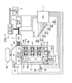
- FIG. 1 shows a parallel hybrid vehicle of an embodiment of the invention, comprising an engine E, a motor M, and a transmission T connected in series.
- the driving forces from both the engine E and the motor M are transmitted to front wheels Wf (rear wheels or front-rear wheels also acceptable) serving as drive wheels, via a transmission T such as an AT (automatic transmission) or the like (manual transmission MT also acceptable).
- a transmission T such as an AT (automatic transmission) or the like
- the motor M functions as a generator to produce so called regenerative braking, and the kinetic energy of the vehicle is recovered as electrical energy.
- the drive and regenerative braking of the motor M are performed by a power drive unit (PDU) 2, which receives control instructions from an ECU 1.
- a nickel-hydrogen battery (power storage unit) 3 of a high-tension system for transferring electrical energy to and from the motor M is connected to the power drive unit 2.
- Reference symbol 4 denotes a 12-volt auxiliary battery for operating various auxiliary equipment, and this auxiliary battery 4 is connected to the battery 3 via a down converter 5 which is a DC-DC converter.
- the down converter 5, which is controlled by the ECU 1, reduces the voltage of the battery 3 to charge the auxiliary battery 4.
- the ECU 1 protects the battery 3, and calculates the state of charge SOC.
- the ECU 1 in addition to controlling the down converter 5, also controls a fuel supply control device (not shown in figure) which controls the amount of fuel supplied to the engine E, and controls the ignition timing and the like. Therefore, inputs to the ECU 1 are: a signal from a speed sensor S1 for detecting the speed VP, a signal from an engine speed sensor S2 for detecting the engine speed NE, a signal from a gear shift position sensor S3 for detecting the shift position SH of the transmission T, a signal from a brake switch S4 for detecting the operation of a brake (Br) pedal, a signal from an accelerator pedal opening sensor S5 which shows accelerator pedal opening, a signal from a throttle opening sensor S6 for detecting throttle opening TH, a signal from an inlet pipe negative pressure sensor S7 for detecting inlet pipe negative pressure PB, and a signal from a battery temperature sensor S8 for detecting temperature TBAT of the battery 3.
- a speed sensor S1 for detecting the speed VP
- an engine speed sensor S2 for detecting the
- Reference symbol BS denotes a brake servo connected to a brake pedal.
- a master power internal negative pressure sensor S9 for detecting the brake master power internal negative pressure is installed in this brake servo BS.
- This master power internal negative pressure sensor S9 is also connected to the ECU 1.
- a POIL sensor S10, the solenoid of a spool valve 6, and a TOIL sensor S11, which are mentioned later, are connected to the ECU 1.
- the engine E is a so called SOHC V6 cylinder engine, and the three cylinders on one bank have a structure provided with a variable valve timing mechanism VT, with which it is possible to deactivate the cylinder operation, while the three cylinders on the other bank have a structure provided with a normal valve operating system (not shown in figure) which does not deactivate operation of the cylinder (cylinder deactivation operation).
- the three cylinders in which cylinder deactivation is possible have a structure in which each of the two inlet valves and the two exhaust valves are able to maintain their closed state by means of the variable valve timing mechanism VT, through the medium of the oil pressure pump 7, the spool valve 6, the cylinder deactivation side path 8, and the cylinder deactivation cancellation side path 9.
- the POIL sensor S10 is provided in the cylinder deactivation cancellation side path 9 and detects the oil pressure of the cylinder deactivation cancellation side path 9 when the cylinders are deactivated.
- the TOIL sensor S11 is provided in the lubrication system piping 14 of the oil pump 7 and detects the oil temperature.
- Reference symbol 15 denotes an electric oil pump, and reference symbol 16 denotes an electronic control throttle (DBW).
- the engine E can be switched between three-cylinder operation (cylinder deactivation operation) in which the three cylinders of one side bank are deactivated, and six cylinder operation (all cylinders operation) in which all six cylinders of both side banks are operating.
- the control modes of this hybrid vehicle are: 'idle mode', 'idle stop mode', 'deceleration mode', 'acceleration mode', and 'cruise mode'.
- the idle mode fuel supply is resumed after fuel supply cut, to maintain the engine E in an idle condition, and in the idle stop mode, for example at the time the engine is stopped, the engine is stopped in a defined condition.
- the motor M performs regenerative braking
- the acceleration mode the motor M drives the engine E
- the cruise mode the motor M is not driven to assist the engine E, so that the vehicle runs under the driving force of the engine E.
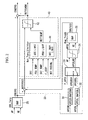
- FIG. 2 is a block diagram showing the ECU in FIG. 1 in more detail.
- the ECU 1 has; a crank shaft torque calculating section 20 which calculates the entire torque required by the crank shaft CRKTRQ, a motor assist amount calculating section 30 which calculates the torque amount of assist possible by the motor M, and a motor torque limiting management section 40 which restricts the amount of torque supplied by the motor M.
- An accelerator pedal depression amount (accelerator pedal opening) AP, and an engine speed NE are input to the crank shaft torque calculating section 20, and from these the crank shaft entire required torque (crank shaft torque) CRKTRQ is retrieved, based on a table CRK_Torq.
- the motor assist amount calculating section 30 obtains the torque able to be supplied by the engine E during cylinder deactivation operation ENGTQCS, for calculating the motor torque MOTTRQ during cylinder deactivation operation by subtracting this torque ENGTQCS from the crank shaft torque.
- the motor assist amount calculating section 30 has accelerator pedal opening threshold value calculating sections 31 and 32 for determining the switching between the cylinder deactivation operation and the all cylinders operation.
- the threshold value calculating section 31 is for calculating a threshold value APCSBSH, which switches from cylinder deactivation operation to all cylinders operation
- the threshold value calculating section 32 is for calculating a threshold value APCSBSL which switches from all cylinders operation to cylinder deactivation operation.
- the threshold value calculating sections 31 and 32 by subtracting predetermined values DAPCSH and DAPCSL from previous threshold values APCSH and APCSL which have been input respectively, the threshold values APCSBSH and APCSBSL having hysteresis can be calculated. In this way, because the threshold value is reciprocated each time, hunting, which switches incessantly between all cylinders operation and cylinder deactivation operation, can be prevented.
- the threshold values APCSBSH and APCSBSL are each input to a threshold value selecting section 33.
- the threshold value selecting section 33 either one of these input threshold values is selected and output to a filter section 34 as a limiting value APCSLMT. Selection of this threshold value is performed by a flag F_APCS which determines the operating condition of the engine E. In the case where the engine E is in cylinder deactivation operation, APCSBSH is selected as the limiting value, and in the case where all cylinders are operating, APCSBSL is selected as the limiting value.
- the limiting value APCSLMT and the actual accelerator pedal opening AP are input to the filter section 34.
- the filter section 34 compares the limiting value APCSLMT and the accelerator pedal opening AP, and selects whichever is smaller. Then, the selected value is transmitted to a cylinder deactivation engine torque calculating section 35, as a cylinder deactivation accelerator opening APCS for at the time of cylinder deactivation operation.
- the cylinder deactivation engine torque calculating section 35 receives inputs of the cylinder deactivation accelerator opening APCS and the engine speed NE, and based on these, retrieves the cylinder deactivation engine torque ENGTQCS able to be supplied at the time of cylinder deactivation operation, from a table Eng_TrqCS.
- This torque MOTTRQCS is transmitted to the motor output limiting management section 40.
- the motor output (torque) limiting management section 40 has a limiting torque calculating section 41, and a filter section 42.
- the limiting torque calculating section 41 calculates the motor torque which is limited by torque limiting factors such as; the state of charge SOC of the battery 3 being the power storage unit, the temperature of the PDU (power drive unit), the temperature of the battery 3, the value of the flag F_CSTP determining whether cylinder deactivation is in operation, and the motor M rating (rated power of the motor M), based on each of these limiting factors. Then, the smallest torque from among these calculated torques is transmitted to the filter section 42 as a limiting motor torque MOTTRQLMT.
- the limiting motor torque MOTTRQLMT and the cylinder deactivation motor torque MOTTRQCS are input to the filter section 42.
- the filter section 42 compares the limiting motor torque MOTTRQLMT and the cylinder deactivation motor torque MOTTRQCS, and whichever is smallest is selected to be the MOTTRQADM.
- This selected torque MOTTRQADM is supplied by the motor M.
- This torque MOTTRQADM is also subtracted from the crank shaft torque CRKTRQ to calculate the engine torque ENGTRQ, and this engine torque ENGTRQ is supplied by the engine E.
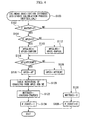
- FIG. 3 is a flow chart showing a cylinder deactivation extended assist calculation process.
- step S100 the cylinder deactivation extended assist calculation process is performed. This calculation process is performed by the motor assist amount calculating section 30. This calculation process is described using FIG. 4.
- step S 102 it is determined whether the value of a flag F_MASTAP, which determines whether cylinder deactivation is possible, is "1" or not. If this determination is "NO”, "0" is substituted for the cylinder deactivation motor torque MOTTRQCS value at step S106, and "0" is substituted for the cylinder deactivation assist flag F_CSAST at step S 108, thereby completing the cylinder deactivation extended assist calculation process.
- step S104 it is determined whether the value of a flag F_APCS is "1" or not.
- This flag F_APCS is a flag which determines the engine operating state, and if the engine E is operating as cylinder deactivation, the value is "1", and if all cylinders are operating, the value is "0".
- step S104 determines whether the determination in step S104 is "YES" or "YES"
- a threshold value APCSLMT is selected to move from cylinder deactivation operation to all cylinders operation (see the process by the threshold value calculating section 31 and the threshold value selecting section 33).
- This threshold value APCSLMT is the predetermined value DAPCSH subtracted from the previous threshold value APCSH. In this way, by changing the threshold value, hunting can be prevented.
- the flow proceeds to step S 114.
- a threshold value APCSLMT is selected to move from all cylinders operation to cylinder deactivation operation (see the process by the threshold value calculating section 32 and the threshold value selecting section 33).
- This threshold value APCSLMT is the predetermined value DAPCSL subtracted from the previous threshold value APCSL.
- the flow proceeds to step S 114.
- step S114 the limiting value APCSLMT and the actual accelerator pedal opening AP are compared, to determine whether the accelerator pedal opening AP is equal to or less than the limiting value APCSLMT. In the case where this determination is "YES”, at step S 116 the actual accelerator pedal opening AP is substituted for the cylinder deactivation accelerator pedal opening APCS, and the flow proceeds to step S 120. In the case where the determination at step S114 is "NO”, at step S118 the limiting value APCSLMT is substituted for the cylinder deactivation accelerator pedal opening APCS, and the flow proceeds to step S120.
- step S120 the cylinder deactivation engine torque ENGTRQCS is obtained from the cylinder deactivation accelerator pedal opening APCS and the engine speed NE by retrieval from a table.
- this cylinder deactivation engine torque ENGTRQCS is subtracted from the required crank shaft torque CRQTRQRQ, to calculate the cylinder deactivation motor torque MOTTRQ.
- "1" is substituted for a cylinder deactivation assist flag F_CSCAST, to complete the assist calculation process.
- step S200 a motor torque limiting process is performed.
- the motor torque limiting process is performed by the motor torque limiting management section 40.
- Motor torques, which are limited from the previously mentioned torque limiting factors, are respectively calculated based on each of these limiting factors, and the smallest from among these torques is calculated as the limiting motor torque MOTTRQLMT.
- step S300 a cylinder deactivation operation authorization determination process is performed.
- the cylinder deactivation motor torque MOTTQCS needed by the cylinder is equal to or less than the limiting motor torque MOTTRQLMT, whether the vehicle operating mode is a standard mode (not a special mode such as starting mode), whether the negative pressure of the inlet pipe is maintaining a reasonable range, whether the gear shift position is in a reasonable position (not neutral or reverse), whether the engine cooling water TW is equal to or above a predetermined value, whether the vehicle speed is equal to or greater than a minimum vehicle speed, whether the engine speed NE of the engine E is equal to or greater than a minimum engine speed, whether the condition of the engine E is normal, whether the range of the catalyser temperature is reasonable, whether the oil pressure of the engine E is reasonable, and so on. When all these conditions have been met, "1" is substituted for the value of the cylinder deactivation operation authorization flag F_CSMAOK.
- step S400 it is determined whether the limiting motor torque MOTTQLMT is larger than the motor cylinder deactivation torque MOTTRQCS. In the case where this determination is "YES”, in step S402 the cylinder deactivation motor torque MOTTRQCS is substituted for the required motor cylinder deactivation torque MOTTCSRQ, and the flow proceeds to step S406. In the case where the determination at step S400 is "NO”, in step S404 the limiting value MOTTRQLMT is substituted for the required motor cylinder deactivation torque MOTTCSRQ, and the flow proceeds to step S406.
- step S406 it is determined whether the value of a cylinder deactivation determination flag F_CSTP is "1". In the case where this determination is "YES”, this is the case where the engine E is in cylinder deactivation operation, and the flow proceeds to step S410, where the required cylinder deactivation motor torque MOTTCSRQ is substituted for a management motor torque MOTTQADM, to complete the process. In the case where the determination at step S406 is "NO", this is the case where the engine E is in all cylinders operation, and in this case the flow proceeds to step S408.
- step S408 it is determined whether the value of the cylinder deactivation motor assist authorization flag F_CSMAOK is "1" or not. In the case where this determination is "YES", because this is a case where it is possible to assist the engine E by supplying torque by the motor M, the flow proceeds to step S410, and the required cylinder deactivation motor torque MOTTCSRQ is substituted for the management motor torque MOTTQADM, to complete the process. In this case, assist is performed by the motor M, and in the case where all cylinders had been operating, the engine is switched to the cylinder deactivation operation.
- step S408 If the determination in step S408 is "NO”, the flow proceeds to step S412, and "0" is substituted for the management motor torque MOTTRQADM value. In this case, assist (supply of torque) by the motor M is not performed, and in the case where the partial cylinder deactivation is in operation, the engine is switched to the all cylinders operation.
- FIG. 5 is a graph showing the relationship between electronic control throttle opening, and the engine torque and accelerator pedal, when moving from cylinder deactivation operation to all cylinders operation.
- the horizontal axis of this graph represents the electronic control throttle opening
- the upper part of the vertical axis represents the engine torque
- the lower part of the vertical axis represents the accelerator pedal opening.
- the lines LP and LQ denote the engine torque depending on the electronic control throttle opening in the cases of all cylinders operation and cylinder deactivation operation, respectively.
- the lines LR and LS denote the accelerator pedal opening (AP) depending on the electronic control throttle opening in the cases of all cylinders operation and cylinder deactivation operation, respectively.
- the electronic control throttle opening depending on the accelerator pedal opening AP is set by the cylinder deactivation time line LS, and the engine torque depending on this set electronic control throttle opening by the line LQ. Consequently, as the accelerator pedal opening becomes greater, the electronic control throttle opening increases along the line LS, and the engine torque depending on this increase in electronic control throttle opening also increases along the line LQ. This control is continued as is until the required torque becomes greater than the torque able to be supplied under cylinder deactivation operation (exceeds engine torque TRQ1).
- the accelerator pedal opening exceeds the threshold value AP 1 (corresponding to APCSH)
- the torque required by the power source ends up exceeding the torque TRQ I able to be supplied under the cylinder deactivation operation.
- the part of the torque which has exceeded the torque TRQ1 is supplied by the motor M, and engine E assist control is performed.
- the electronic control throttle opening is maintained at the threshold value W1 at the time of AP, and as a result the torque supplied by the engine E is maintained at TRQ1.
- the torque supplied by the engine E can be maintained at a constant.
- the torque TRQ1 is set at such that a value of the specific fuel consumption becomes the lowest.
- fuel supplied to the engine E can be used extremely effectively, and it becomes possible to greatly contribute to an improvement in fuel consumption efficiency.
- This control is continued as is until the required torque becomes greater (exceeds torque TRQ2) than the sum of the torque able to be supplied by the engine E under cylinder deactivation operation and the torque able to be supplied by the motor M.
- the accelerator pedal opening AP exceeds the threshold value AP2
- the torque required by the power source ends up exceeding the sum of the torque TRQ1 able to be supplied by the engine E under cylinder deactivation operation and the torque able to be supplied by the motor M.
- the torque supplied from the motor M is switched to "0"
- the operating state of the engine E moves from cylinder deactivation to all cylinders operating.
- the electronic control throttle opening changes from the opening W1 corresponding to the engine torque TRQ1, to the opening W2 corresponding to the engine torque TRQ2, to perform control so that shock caused by changing the engine torque does not occur.
- the electronic control throttle opening is controlled along the line LR, and the engine E performs all cylinders operation along the line LP.
- the torque TRQ2 for switching from the cylinder deactivation operation to all cylinders operation changes depending on the torque able to be supplied by the motor M.
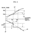
- FIG. 6 is a diagram explaining the case where the engine operating state moves from all cylinders operation to cylinder deactivation operation.
- the horizontal axis of this graph represents the electronic control throttle opening
- the upper part of the vertical axis represents the engine torque
- the lower part of the vertical axis represents the accelerator pedal opening.
- the lines LP, LQ, and LR, LS respectively denote the engine torque and the accelerator pedal opening depending on the electronic control throttle opening in the cases of all cylinders operation and cylinder deactivation operation.
- the required torque becomes smaller than the sum (engine torque TRQ4) of the torque TRQ3 able to be supplied by the engine E under the cylinder deactivation operation and the torque able to be supplied by the motor M.
- the torque supplied from the engine E is immediately changed from all cylinders operation torque TRQ4 to cylinder deactivation operation torque TRQ3, to move from all cylinders operation to cylinder deactivation operation.
- the part of the torque exceeding the torque TRQ3 of the supplied torque is supplied by the motor M.
- immediately switching the electronic control throttle opening from W4 to W3 adjusts the torque change according to the operating state change.
- the torque TRQ3 under cylinder deactivation operation is set to the lowest torque for yielding the lowest net fuel consumption, and contributes to an improvement in fuel consumption efficiency.
- the accelerator pedal opening AP becomes smaller than the threshold value AP3 (corresponding to APCSL)
- the torque required by the power source becomes smaller than the engine torque TRQ3, and due to the assist by the motor M becoming unnecessary, the torque supplied by the motor M switches to "0".
- the electronic control throttle opening is controlled along the line LS, and the engine E performs cylinder deactivation operation along the line LQ.
- the determination of the switching between cylinder deactivation operation and all cylinders operation was performed based on the torque of the engine and the motor.
- control instead of this, it is possible for control to be performed based on the output of the engine and the motor.
- fuel supplied by the engine can be used extremely effectively, and it becomes possible to greatly contribute to an improvement in fuel consumption efficiency.
- the possibility of discomfort occurring when switching operating states can be further reduced.
- the possibility of discomfort occurring can be reduced, without changing the driving force characteristics of the vehicle with respect to the operation of the accelerator pedal.
- a control apparatus 1 for a hybrid vehicle which comprises as a power source a motor M and an engine E capable of executing partial cylinder deactivation operation and the driving force of at least one of these is transmitted to wheels for running the vehicle.
- the control apparatus operates the engine under partial deactivation and adjusts the motor output so as to compensate the difference between the total output of the power source and the output of the partial cylinder deactivated engine.
Landscapes
- Engineering & Computer Science (AREA)
- Chemical & Material Sciences (AREA)
- Combustion & Propulsion (AREA)
- Mechanical Engineering (AREA)
- Transportation (AREA)
- General Engineering & Computer Science (AREA)
- Automation & Control Theory (AREA)
- Output Control And Ontrol Of Special Type Engine (AREA)
- Hybrid Electric Vehicles (AREA)
- Control Of Vehicle Engines Or Engines For Specific Uses (AREA)
- Arrangement Of Transmissions (AREA)
- Electrical Control Of Air Or Fuel Supplied To Internal-Combustion Engine (AREA)
- Electric Propulsion And Braking For Vehicles (AREA)
Applications Claiming Priority (2)
| Application Number | Priority Date | Filing Date | Title |
|---|---|---|---|
| JP2002231726 | 2002-08-08 | ||
| JP2002231726A JP3607269B2 (ja) | 2002-08-08 | 2002-08-08 | ハイブリッド車両の制御装置 |
Publications (3)
| Publication Number | Publication Date |
|---|---|
| EP1388450A2 true EP1388450A2 (fr) | 2004-02-11 |
| EP1388450A3 EP1388450A3 (fr) | 2004-06-09 |
| EP1388450B1 EP1388450B1 (fr) | 2006-06-21 |
Family
ID=30437776
Family Applications (1)
| Application Number | Title | Priority Date | Filing Date |
|---|---|---|---|
| EP03017462A Expired - Lifetime EP1388450B1 (fr) | 2002-08-08 | 2003-08-01 | Dispositif de commande pour véhicule hybride |
Country Status (5)
| Country | Link |
|---|---|
| US (1) | US6886524B2 (fr) |
| EP (1) | EP1388450B1 (fr) |
| JP (1) | JP3607269B2 (fr) |
| CA (1) | CA2436652C (fr) |
| DE (1) | DE60306273T2 (fr) |
Cited By (9)
| Publication number | Priority date | Publication date | Assignee | Title |
|---|---|---|---|---|
| US6943460B2 (en) * | 2002-07-16 | 2005-09-13 | Honda Giken Kogyo Kabushiki Kaisha | Control device for hybrid vehicle |
| EP1577510A3 (fr) * | 2004-03-19 | 2008-12-31 | Ford Global Technologies, LLC | Méthode de contrôle d'une soupape commandée électromécaniquement pour un moteur à combustion interne |
| EP2055596A2 (fr) | 2007-11-05 | 2009-05-06 | GM Global Technology Operations, Inc. | Procédé de fonctionnement d'un système de transmission pour contrôler la stabilisation du moteur thermique |
| US7650745B2 (en) | 2004-03-19 | 2010-01-26 | Ford Global Technologies, Llc | Method to reduce engine emissions for an engine capable of multi-stroke operation and having a catalyst |
| EP2055566A3 (fr) * | 2007-11-05 | 2012-02-22 | GM Global Technology Operations LLC | Procédé de sélection préférentielle de mode, engrenage et vitesse d'entrée en fonction de plusieurs coûts d'alimentation en carburant d'un état du moteur pour un système de propulsion hybride |
| EP2055587A3 (fr) * | 2007-11-04 | 2012-04-11 | GM Global Technology Operations LLC | Procédé de contrôle de la puissance de sortie d'un dispositif de stockage d'énergie dans un système de transmission |
| WO2012056135A1 (fr) * | 2010-10-28 | 2012-05-03 | Peugeot Citroën Automobiles SA | Procede de limitation du couple maximum que peut delivrer ou recevoir une machine electrique alimentee par une batterie et chaîne de traction pour vehicule hybride mettant en oeuvre le procede |
| EP3217004A1 (fr) * | 2016-03-07 | 2017-09-13 | Ford Global Technologies, LLC | Procédé de commande d'un moteur |
| EP4049875A1 (fr) * | 2021-02-24 | 2022-08-31 | Toyota Jidosha Kabushiki Kaisha | Organe de commande pour véhicule électrique hybride et procédé de commande pour véhicule électrique hybride |
Families Citing this family (49)
| Publication number | Priority date | Publication date | Assignee | Title |
|---|---|---|---|---|
| JP3701567B2 (ja) * | 2001-02-20 | 2005-09-28 | 本田技研工業株式会社 | ハイブリッド車両の制御装置 |
| US20020163198A1 (en) * | 2001-05-03 | 2002-11-07 | Gee Thomas Scott | Fail-safe engine cooling control algorithm for hybrid electric vehicle |
| JP3665060B2 (ja) * | 2003-07-04 | 2005-06-29 | 本田技研工業株式会社 | ハイブリッド車両の制御装置 |
| US7308959B2 (en) * | 2003-09-15 | 2007-12-18 | General Motors Corporation | Displacement on demand with regenerative braking |
| US7072758B2 (en) | 2004-03-19 | 2006-07-04 | Ford Global Technologies, Llc | Method of torque control for an engine with valves that may be deactivated |
| US7383820B2 (en) | 2004-03-19 | 2008-06-10 | Ford Global Technologies, Llc | Electromechanical valve timing during a start |
| US7021289B2 (en) | 2004-03-19 | 2006-04-04 | Ford Global Technology, Llc | Reducing engine emissions on an engine with electromechanical valves |
| US7128043B2 (en) | 2004-03-19 | 2006-10-31 | Ford Global Technologies, Llc | Electromechanically actuated valve control based on a vehicle electrical system |
| JP4153006B2 (ja) * | 2004-07-23 | 2008-09-17 | 本田技研工業株式会社 | ハイブリッド車両の制御装置 |
| US7085631B2 (en) * | 2004-07-29 | 2006-08-01 | Ford Global Technologies, Llc | Vehicle and method for operating an engine in a vehicle |
| US7225782B2 (en) * | 2005-03-03 | 2007-06-05 | Ford Global Technologies, Llc | System and method to control transitions in the number of cylinders in a hybrid vehicle |
| US7063064B1 (en) * | 2005-04-04 | 2006-06-20 | Marcos Ribeiro | Progressive combustion engine |
| JP4361509B2 (ja) * | 2005-04-13 | 2009-11-11 | 本田技研工業株式会社 | ハイブリッド車両の制御装置 |
| US7748353B2 (en) * | 2006-03-02 | 2010-07-06 | Ford Global Technologies, Llc | Hydraulic actuation system for improved engine control |
| US7546821B2 (en) * | 2006-03-02 | 2009-06-16 | Ford Global Technologies, Llc | Hydraulic actuation system for improved engine start |
| JPWO2008026480A1 (ja) * | 2006-08-30 | 2010-01-21 | アイシン精機株式会社 | 車両の駆動源制御装置 |
| DE102006055800A1 (de) * | 2006-11-27 | 2008-05-29 | Robert Bosch Gmbh | Hybridantrieb mit Ventilabschaltung |
| US8464690B2 (en) | 2008-07-11 | 2013-06-18 | Tula Technology, Inc. | Hybrid vehicle with cylinder deactivation |
| DE102008064538A1 (de) * | 2008-12-19 | 2010-06-24 | Dr. Ing. H.C. F. Porsche Aktiengesellschaft | Verfahren zum Betreiben eines Hybridfahrzeuges |
| FR2941551B1 (fr) * | 2009-01-28 | 2011-06-03 | Airbus France | Circuit electronique de determination d'une donnee representative d'un parametre de l'air et systeme comprenant un tel circuit |
| JP4726966B2 (ja) * | 2009-01-30 | 2011-07-20 | エンパイア テクノロジー ディベロップメント エルエルシー | ハイブリッド車両用駆動装置、ハイブリッド車両及び駆動方法 |
| CN102939214B (zh) * | 2010-06-15 | 2015-08-19 | 本田技研工业株式会社 | 混合动力车辆用驱动装置 |
| US8880258B2 (en) | 2011-10-17 | 2014-11-04 | Tula Technology, Inc. | Hybrid powertrain control |
| WO2013059365A1 (fr) * | 2011-10-17 | 2013-04-25 | Tula Technology, Inc. | Véhicule hybride à désactivation de cylindre |
| JP5803892B2 (ja) * | 2012-12-18 | 2015-11-04 | トヨタ自動車株式会社 | ハイブリッド車両の制御装置 |
| JP6036750B2 (ja) | 2014-06-04 | 2016-11-30 | トヨタ自動車株式会社 | 内燃機関の制御装置 |
| US10196995B2 (en) | 2015-01-12 | 2019-02-05 | Tula Technology, Inc. | Engine torque smoothing |
| CN110043378B (zh) | 2015-01-12 | 2021-10-29 | 图拉技术公司 | 动力传动系控制器及操作内燃发动机的方法 |
| US10060368B2 (en) | 2015-01-12 | 2018-08-28 | Tula Technology, Inc. | Engine torque smoothing |
| US10578037B2 (en) | 2015-01-12 | 2020-03-03 | Tula Technology, Inc. | Adaptive torque mitigation by micro-hybrid system |
| US10344692B2 (en) | 2015-01-12 | 2019-07-09 | Tula Technology, Inc. | Adaptive torque mitigation by micro-hybrid system |
| US10183672B2 (en) * | 2016-08-30 | 2019-01-22 | GM Global Technology Operations LLC | Method to optimize engine operation using active fuel management |
| DE102016117556B4 (de) * | 2016-09-19 | 2019-12-12 | Volkswagen Aktiengesellschaft | Verfahren zum Betreiben eines Antriebssystems und Antriebssystem |
| DE102016125607A1 (de) | 2016-12-23 | 2018-06-28 | Volkswagen Aktiengesellschaft | Verfahren zum Betreiben eines Antriebssystems, Antriebssystem und Kraftfahrzeug |
| US10954877B2 (en) | 2017-03-13 | 2021-03-23 | Tula Technology, Inc. | Adaptive torque mitigation by micro-hybrid system |
| US10780772B2 (en) * | 2018-10-23 | 2020-09-22 | Ge Global Sourcing Llc | Vehicle engine assist system |
| JP7331367B2 (ja) * | 2019-01-24 | 2023-08-23 | マツダ株式会社 | ハイブリッド車両の制御装置 |
| JP7225840B2 (ja) * | 2019-01-24 | 2023-02-21 | マツダ株式会社 | ハイブリッド車両の制御装置 |
| CN113661316B (zh) * | 2019-04-04 | 2024-03-08 | 卡明斯公司 | 具有气缸停用控制的内燃发动机的循环应用 |
| US11383696B2 (en) * | 2019-06-12 | 2022-07-12 | GM Global Technology Operations LLC | Method and apparatus for controlling a powertrain system |
| WO2021026128A1 (fr) * | 2019-08-05 | 2021-02-11 | Cummins Inc. | Retardement de la réactivation de cylindre |
| JP2021167587A (ja) * | 2020-04-10 | 2021-10-21 | トヨタ自動車株式会社 | エンジン装置およびこれを備えるハイブリッド自動車 |
| US11378022B2 (en) | 2020-08-03 | 2022-07-05 | Cummins Inc. | Systems and methods for controlling cylinder deactivation operation in electrified powertrains |
| JP7327342B2 (ja) * | 2020-10-08 | 2023-08-16 | トヨタ自動車株式会社 | ハイブリッド車両の制御装置 |
| US11555461B2 (en) | 2020-10-20 | 2023-01-17 | Tula Technology, Inc. | Noise, vibration and harshness reduction in a skip fire engine control system |
| JP7327356B2 (ja) * | 2020-11-06 | 2023-08-16 | トヨタ自動車株式会社 | 多気筒内燃機関の点火時期制御装置 |
| JP7528800B2 (ja) * | 2021-01-29 | 2024-08-06 | トヨタ自動車株式会社 | ハイブリッド車両の制御装置 |
| US11499490B1 (en) * | 2021-12-07 | 2022-11-15 | Cummins Inc. | Systems and methods to minimize emissions spikes when reactivating or deactivating a combustion cylinder |
| JP7700735B2 (ja) * | 2022-06-15 | 2025-07-01 | トヨタ自動車株式会社 | 車両の制御装置 |
Family Cites Families (11)
| Publication number | Priority date | Publication date | Assignee | Title |
|---|---|---|---|---|
| US6116363A (en) * | 1995-05-31 | 2000-09-12 | Frank Transportation Technology, Llc | Fuel consumption control for charge depletion hybrid electric vehicles |
| EP0755816A3 (fr) * | 1995-07-28 | 1998-09-02 | Isuzu Ceramics Research Institute Co., Ltd. | Véhicule électrique hybride |
| DE69621759T2 (de) | 1995-12-27 | 2003-02-06 | Denso Corp | Stromversorgungssteuervorrichtung für ein Hybrid-Fahrzeug |
| JP3575255B2 (ja) | 1997-12-15 | 2004-10-13 | 日産自動車株式会社 | ハイブリッド車の作動気筒数制御装置 |
| JPH11350995A (ja) | 1998-06-08 | 1999-12-21 | Honda Motor Co Ltd | ハイブリッド駆動装置 |
| JP3721787B2 (ja) | 1998-07-09 | 2005-11-30 | 日産自動車株式会社 | ハイブリッド車両の制御装置 |
| JP2001207886A (ja) | 2000-01-24 | 2001-08-03 | Daihatsu Motor Co Ltd | ハイブリッド自動車の制御装置 |
| DE10008287B4 (de) * | 2000-02-23 | 2009-09-10 | Temic Automotive Electric Motors Gmbh | Fahrzeug-Antriebssystem und Verfahren zum Betreiben eines Fahrzeug-Antriebssystems |
| US6691807B1 (en) * | 2000-04-11 | 2004-02-17 | Ford Global Technologies Llc | Hybrid electric vehicle with variable displacement engine |
| JP4135302B2 (ja) * | 2000-08-09 | 2008-08-20 | トヨタ自動車株式会社 | 燃料電池を搭載したハイブリッド車両 |
| JP3783536B2 (ja) * | 2000-08-28 | 2006-06-07 | トヨタ自動車株式会社 | 車両の制御装置 |
-
2002
- 2002-08-08 JP JP2002231726A patent/JP3607269B2/ja not_active Expired - Fee Related
-
2003
- 2003-08-01 DE DE60306273T patent/DE60306273T2/de not_active Expired - Lifetime
- 2003-08-01 EP EP03017462A patent/EP1388450B1/fr not_active Expired - Lifetime
- 2003-08-05 US US10/633,569 patent/US6886524B2/en not_active Expired - Lifetime
- 2003-08-05 CA CA002436652A patent/CA2436652C/fr not_active Expired - Fee Related
Cited By (16)
| Publication number | Priority date | Publication date | Assignee | Title |
|---|---|---|---|---|
| US6943460B2 (en) * | 2002-07-16 | 2005-09-13 | Honda Giken Kogyo Kabushiki Kaisha | Control device for hybrid vehicle |
| EP1577510A3 (fr) * | 2004-03-19 | 2008-12-31 | Ford Global Technologies, LLC | Méthode de contrôle d'une soupape commandée électromécaniquement pour un moteur à combustion interne |
| US7650745B2 (en) | 2004-03-19 | 2010-01-26 | Ford Global Technologies, Llc | Method to reduce engine emissions for an engine capable of multi-stroke operation and having a catalyst |
| US8191355B2 (en) | 2004-03-19 | 2012-06-05 | Ford Global Technologies, Llc | Method to reduce engine emissions for an engine capable of multi-stroke operation and having a catalyst |
| EP2055587A3 (fr) * | 2007-11-04 | 2012-04-11 | GM Global Technology Operations LLC | Procédé de contrôle de la puissance de sortie d'un dispositif de stockage d'énergie dans un système de transmission |
| US8229633B2 (en) | 2007-11-05 | 2012-07-24 | GM Global Technology Operations LLC | Method for operating a powertrain system to control engine stabilization |
| EP2055596A2 (fr) | 2007-11-05 | 2009-05-06 | GM Global Technology Operations, Inc. | Procédé de fonctionnement d'un système de transmission pour contrôler la stabilisation du moteur thermique |
| EP2055596A3 (fr) * | 2007-11-05 | 2011-01-26 | GM Global Technology Operations, Inc. | Procédé de fonctionnement d'un système de transmission pour contrôler la stabilisation du moteur thermique |
| EP2055566A3 (fr) * | 2007-11-05 | 2012-02-22 | GM Global Technology Operations LLC | Procédé de sélection préférentielle de mode, engrenage et vitesse d'entrée en fonction de plusieurs coûts d'alimentation en carburant d'un état du moteur pour un système de propulsion hybride |
| CN101508290B (zh) * | 2007-11-05 | 2013-07-24 | 通用汽车环球科技运作公司 | 用于操作动力系统来控制发动机稳定性的方法 |
| FR2966991A1 (fr) * | 2010-10-28 | 2012-05-04 | Peugeot Citroen Automobiles Sa | Procede de limitation du couple maximum que peut delivrer ou recevoir une machine electrique alimentee par une batterie et chaine de traction pour vehicule hybride mettant en oeuvre le procede |
| WO2012056135A1 (fr) * | 2010-10-28 | 2012-05-03 | Peugeot Citroën Automobiles SA | Procede de limitation du couple maximum que peut delivrer ou recevoir une machine electrique alimentee par une batterie et chaîne de traction pour vehicule hybride mettant en oeuvre le procede |
| EP3217004A1 (fr) * | 2016-03-07 | 2017-09-13 | Ford Global Technologies, LLC | Procédé de commande d'un moteur |
| US10337432B2 (en) | 2016-03-07 | 2019-07-02 | Ford Global Technologies, Llc | Vehicle and method of controlling a vehicle |
| EP4049875A1 (fr) * | 2021-02-24 | 2022-08-31 | Toyota Jidosha Kabushiki Kaisha | Organe de commande pour véhicule électrique hybride et procédé de commande pour véhicule électrique hybride |
| US11807216B2 (en) | 2021-02-24 | 2023-11-07 | Toyota Jidosha Kabushiki Kaisha | Controller for hybrid electric vehicle and control method for hybrid electric vehicle |
Also Published As
| Publication number | Publication date |
|---|---|
| DE60306273D1 (de) | 2006-08-03 |
| US6886524B2 (en) | 2005-05-03 |
| JP3607269B2 (ja) | 2005-01-05 |
| CA2436652C (fr) | 2006-07-04 |
| US20040035113A1 (en) | 2004-02-26 |
| CA2436652A1 (fr) | 2004-02-08 |
| JP2004068759A (ja) | 2004-03-04 |
| EP1388450B1 (fr) | 2006-06-21 |
| EP1388450A3 (fr) | 2004-06-09 |
| DE60306273T2 (de) | 2006-11-02 |
Similar Documents
| Publication | Publication Date | Title |
|---|---|---|
| EP1388450B1 (fr) | Dispositif de commande pour véhicule hybride | |
| JP3466600B1 (ja) | ハイブリッド車両の制御装置 | |
| US8417408B2 (en) | Drive control apparatus for hybrid vehicle | |
| US6687603B2 (en) | Assist control apparatus for hybrid vehicle | |
| JP3817516B2 (ja) | ハイブリッド車両の駆動制御装置 | |
| JP3665060B2 (ja) | ハイブリッド車両の制御装置 | |
| US6843337B2 (en) | Control system and method for hybrid vehicle | |
| US7059997B2 (en) | Engine system with cylinder number variable engine and method for controlling the engine system | |
| US7059435B2 (en) | Control apparatus for hybrid vehicle | |
| CA2460470C (fr) | Dispositif de controle du moteur pour vehicule dont la decelaration du moteur peut etre desactive | |
| EP1493604B1 (fr) | Dispositif de commande pour véhicule hybride | |
| EP1493608B1 (fr) | Appareil de commande pour véhicule hybride | |
| US20030102175A1 (en) | Control device for hybrid vehicle | |
| WO2011078189A1 (fr) | Dispositif de commande pour véhicule hybride | |
| JP4153006B2 (ja) | ハイブリッド車両の制御装置 | |
| JP3454172B2 (ja) | ハイブリッド車両の制御方法 | |
| US7146958B2 (en) | Control apparatus for hybrid vehicle | |
| JP4252542B2 (ja) | ハイブリッド車両の変速制御装置 | |
| JP2000245011A (ja) | ハイブリッド自動車の制御装置 |
Legal Events
| Date | Code | Title | Description |
|---|---|---|---|
| PUAI | Public reference made under article 153(3) epc to a published international application that has entered the european phase |
Free format text: ORIGINAL CODE: 0009012 |
|
| AK | Designated contracting states |
Kind code of ref document: A2 Designated state(s): AT BE BG CH CY CZ DE DK EE ES FI FR GB GR HU IE IT LI LU MC NL PT RO SE SI SK TR |
|
| AX | Request for extension of the european patent |
Extension state: AL LT LV MK |
|
| PUAL | Search report despatched |
Free format text: ORIGINAL CODE: 0009013 |
|
| AK | Designated contracting states |
Kind code of ref document: A3 Designated state(s): AT BE BG CH CY CZ DE DK EE ES FI FR GB GR HU IE IT LI LU MC NL PT RO SE SI SK TR |
|
| AX | Request for extension of the european patent |
Extension state: AL LT LV MK |
|
| 17P | Request for examination filed |
Effective date: 20040916 |
|
| 17Q | First examination report despatched |
Effective date: 20050105 |
|
| AKX | Designation fees paid |
Designated state(s): DE GB |
|
| GRAP | Despatch of communication of intention to grant a patent |
Free format text: ORIGINAL CODE: EPIDOSNIGR1 |
|
| GRAS | Grant fee paid |
Free format text: ORIGINAL CODE: EPIDOSNIGR3 |
|
| GRAA | (expected) grant |
Free format text: ORIGINAL CODE: 0009210 |
|
| AK | Designated contracting states |
Kind code of ref document: B1 Designated state(s): DE GB |
|
| REG | Reference to a national code |
Ref country code: GB Ref legal event code: FG4D |
|
| REF | Corresponds to: |
Ref document number: 60306273 Country of ref document: DE Date of ref document: 20060803 Kind code of ref document: P |
|
| PLBE | No opposition filed within time limit |
Free format text: ORIGINAL CODE: 0009261 |
|
| STAA | Information on the status of an ep patent application or granted ep patent |
Free format text: STATUS: NO OPPOSITION FILED WITHIN TIME LIMIT |
|
| 26N | No opposition filed |
Effective date: 20070322 |
|
| PGFP | Annual fee paid to national office [announced via postgrant information from national office to epo] |
Ref country code: GB Payment date: 20110727 Year of fee payment: 9 Ref country code: DE Payment date: 20110727 Year of fee payment: 9 |
|
| GBPC | Gb: european patent ceased through non-payment of renewal fee |
Effective date: 20120801 |
|
| PG25 | Lapsed in a contracting state [announced via postgrant information from national office to epo] |
Ref country code: DE Free format text: LAPSE BECAUSE OF NON-PAYMENT OF DUE FEES Effective date: 20130301 Ref country code: GB Free format text: LAPSE BECAUSE OF NON-PAYMENT OF DUE FEES Effective date: 20120801 |
|
| REG | Reference to a national code |
Ref country code: DE Ref legal event code: R119 Ref document number: 60306273 Country of ref document: DE Effective date: 20130301 |