EP1388525A2 - Procédé de fabrication d'une préforme pour fibres optiques et la préforme et la fibre optique capables d'être obtenues par le procédé - Google Patents
Procédé de fabrication d'une préforme pour fibres optiques et la préforme et la fibre optique capables d'être obtenues par le procédé Download PDFInfo
- Publication number
- EP1388525A2 EP1388525A2 EP03090239A EP03090239A EP1388525A2 EP 1388525 A2 EP1388525 A2 EP 1388525A2 EP 03090239 A EP03090239 A EP 03090239A EP 03090239 A EP03090239 A EP 03090239A EP 1388525 A2 EP1388525 A2 EP 1388525A2
- Authority
- EP
- European Patent Office
- Prior art keywords
- clad layer
- optical fiber
- preform
- viscosity
- rod
- Prior art date
- Legal status (The legal status is an assumption and is not a legal conclusion. Google has not performed a legal analysis and makes no representation as to the accuracy of the status listed.)
- Granted
Links
- 239000013307 optical fiber Substances 0.000 title claims abstract description 137
- 238000004519 manufacturing process Methods 0.000 title claims abstract description 18
- 238000000034 method Methods 0.000 title claims description 42
- VYPSYNLAJGMNEJ-UHFFFAOYSA-N Silicium dioxide Chemical compound O=[Si]=O VYPSYNLAJGMNEJ-UHFFFAOYSA-N 0.000 claims abstract description 48
- 239000001257 hydrogen Substances 0.000 claims abstract description 31
- 229910052739 hydrogen Inorganic materials 0.000 claims abstract description 31
- 238000000151 deposition Methods 0.000 claims abstract description 14
- 230000007062 hydrolysis Effects 0.000 claims abstract description 10
- 238000006460 hydrolysis reaction Methods 0.000 claims abstract description 10
- 229910052801 chlorine Inorganic materials 0.000 claims abstract description 6
- 229910052698 phosphorus Inorganic materials 0.000 claims abstract description 4
- 239000011521 glass Substances 0.000 claims description 43
- 230000005540 biological transmission Effects 0.000 claims description 28
- UFHFLCQGNIYNRP-UHFFFAOYSA-N Hydrogen Chemical compound [H][H] UFHFLCQGNIYNRP-UHFFFAOYSA-N 0.000 claims description 25
- 238000010438 heat treatment Methods 0.000 claims description 22
- 238000009826 distribution Methods 0.000 claims description 19
- 239000007789 gas Substances 0.000 claims description 16
- 239000002019 doping agent Substances 0.000 claims description 13
- 239000013058 crude material Substances 0.000 claims description 10
- 239000002245 particle Substances 0.000 claims description 9
- 229910052710 silicon Inorganic materials 0.000 claims description 9
- 239000010703 silicon Substances 0.000 claims description 9
- 239000010453 quartz Substances 0.000 claims description 7
- 230000018044 dehydration Effects 0.000 claims description 6
- 238000006297 dehydration reaction Methods 0.000 claims description 6
- ZAMOUSCENKQFHK-UHFFFAOYSA-N Chlorine atom Chemical compound [Cl] ZAMOUSCENKQFHK-UHFFFAOYSA-N 0.000 claims description 5
- 239000000460 chlorine Substances 0.000 claims description 5
- 229910052732 germanium Inorganic materials 0.000 claims description 5
- GNPVGFCGXDBREM-UHFFFAOYSA-N germanium atom Chemical compound [Ge] GNPVGFCGXDBREM-UHFFFAOYSA-N 0.000 claims description 5
- 238000002425 crystallisation Methods 0.000 claims description 4
- 230000008025 crystallization Effects 0.000 claims description 4
- KZBUYRJDOAKODT-UHFFFAOYSA-N Chlorine Chemical compound ClCl KZBUYRJDOAKODT-UHFFFAOYSA-N 0.000 claims description 3
- PXGOKWXKJXAPGV-UHFFFAOYSA-N Fluorine Chemical compound FF PXGOKWXKJXAPGV-UHFFFAOYSA-N 0.000 claims description 3
- OAICVXFJPJFONN-UHFFFAOYSA-N Phosphorus Chemical compound [P] OAICVXFJPJFONN-UHFFFAOYSA-N 0.000 claims description 3
- 239000013078 crystal Substances 0.000 claims description 3
- 229910052731 fluorine Inorganic materials 0.000 claims description 3
- 239000011737 fluorine Substances 0.000 claims description 3
- 239000011574 phosphorus Substances 0.000 claims description 3
- 239000000377 silicon dioxide Substances 0.000 claims description 3
- 239000000835 fiber Substances 0.000 abstract description 11
- 239000000463 material Substances 0.000 abstract description 8
- 238000005253 cladding Methods 0.000 abstract 3
- 229910002026 crystalline silica Inorganic materials 0.000 abstract 1
- 230000008021 deposition Effects 0.000 abstract 1
- 125000004435 hydrogen atom Chemical class [H]* 0.000 abstract 1
- 235000012239 silicon dioxide Nutrition 0.000 abstract 1
- 239000000203 mixture Substances 0.000 description 11
- 230000000052 comparative effect Effects 0.000 description 10
- 230000007547 defect Effects 0.000 description 7
- 125000002887 hydroxy group Chemical group [H]O* 0.000 description 7
- 238000005245 sintering Methods 0.000 description 6
- 150000002431 hydrogen Chemical class 0.000 description 5
- 238000004891 communication Methods 0.000 description 3
- 239000013081 microcrystal Substances 0.000 description 3
- 229910052906 cristobalite Inorganic materials 0.000 description 2
- VXEGSRKPIUDPQT-UHFFFAOYSA-N 4-[4-(4-methoxyphenyl)piperazin-1-yl]aniline Chemical compound C1=CC(OC)=CC=C1N1CCN(C=2C=CC(N)=CC=2)CC1 VXEGSRKPIUDPQT-UHFFFAOYSA-N 0.000 description 1
- 238000010521 absorption reaction Methods 0.000 description 1
- 230000003247 decreasing effect Effects 0.000 description 1
- 230000001419 dependent effect Effects 0.000 description 1
- 230000000694 effects Effects 0.000 description 1
- 238000005516 engineering process Methods 0.000 description 1
- 239000001307 helium Substances 0.000 description 1
- 229910052734 helium Inorganic materials 0.000 description 1
- SWQJXJOGLNCZEY-UHFFFAOYSA-N helium atom Chemical compound [He] SWQJXJOGLNCZEY-UHFFFAOYSA-N 0.000 description 1
- 230000003301 hydrolyzing effect Effects 0.000 description 1
- 239000011261 inert gas Substances 0.000 description 1
- 230000002427 irreversible effect Effects 0.000 description 1
- 230000001590 oxidative effect Effects 0.000 description 1
- 239000012495 reaction gas Substances 0.000 description 1
- 230000001172 regenerating effect Effects 0.000 description 1
- 239000004065 semiconductor Substances 0.000 description 1
- 230000035945 sensitivity Effects 0.000 description 1
- 239000005049 silicon tetrachloride Substances 0.000 description 1
- 238000001228 spectrum Methods 0.000 description 1
- 238000006467 substitution reaction Methods 0.000 description 1
- 238000004804 winding Methods 0.000 description 1
Images




Classifications
-
- G—PHYSICS
- G02—OPTICS
- G02B—OPTICAL ELEMENTS, SYSTEMS OR APPARATUS
- G02B6/00—Light guides; Structural details of arrangements comprising light guides and other optical elements, e.g. couplings
-
- C—CHEMISTRY; METALLURGY
- C03—GLASS; MINERAL OR SLAG WOOL
- C03C—CHEMICAL COMPOSITION OF GLASSES, GLAZES OR VITREOUS ENAMELS; SURFACE TREATMENT OF GLASS; SURFACE TREATMENT OF FIBRES OR FILAMENTS MADE FROM GLASS, MINERALS OR SLAGS; JOINING GLASS TO GLASS OR OTHER MATERIALS
- C03C13/00—Fibre or filament compositions
- C03C13/04—Fibre optics, e.g. core and clad fibre compositions
- C03C13/045—Silica-containing oxide glass compositions
-
- C—CHEMISTRY; METALLURGY
- C03—GLASS; MINERAL OR SLAG WOOL
- C03B—MANUFACTURE, SHAPING, OR SUPPLEMENTARY PROCESSES
- C03B37/00—Manufacture or treatment of flakes, fibres, or filaments from softened glass, minerals, or slags
- C03B37/01—Manufacture of glass fibres or filaments
- C03B37/012—Manufacture of preforms for drawing fibres or filaments
- C03B37/01205—Manufacture of preforms for drawing fibres or filaments starting from tubes, rods, fibres or filaments
- C03B37/01211—Manufacture of preforms for drawing fibres or filaments starting from tubes, rods, fibres or filaments by inserting one or more rods or tubes into a tube
-
- C—CHEMISTRY; METALLURGY
- C03—GLASS; MINERAL OR SLAG WOOL
- C03B—MANUFACTURE, SHAPING, OR SUPPLEMENTARY PROCESSES
- C03B37/00—Manufacture or treatment of flakes, fibres, or filaments from softened glass, minerals, or slags
- C03B37/01—Manufacture of glass fibres or filaments
- C03B37/012—Manufacture of preforms for drawing fibres or filaments
- C03B37/0128—Manufacture of preforms for drawing fibres or filaments starting from pulverulent glass
- C03B37/01291—Manufacture of preforms for drawing fibres or filaments starting from pulverulent glass by progressive melting, e.g. melting glass powder during delivery to and adhering the so-formed melt to a target or preform, e.g. the Plasma Oxidation Deposition [POD] process
-
- C—CHEMISTRY; METALLURGY
- C03—GLASS; MINERAL OR SLAG WOOL
- C03B—MANUFACTURE, SHAPING, OR SUPPLEMENTARY PROCESSES
- C03B37/00—Manufacture or treatment of flakes, fibres, or filaments from softened glass, minerals, or slags
- C03B37/01—Manufacture of glass fibres or filaments
- C03B37/012—Manufacture of preforms for drawing fibres or filaments
- C03B37/014—Manufacture of preforms for drawing fibres or filaments made entirely or partially by chemical means, e.g. vapour phase deposition of bulk porous glass either by outside vapour deposition [OVD], or by outside vapour phase oxidation [OVPO] or by vapour axial deposition [VAD]
- C03B37/01446—Thermal after-treatment of preforms, e.g. dehydrating, consolidating, sintering
-
- G—PHYSICS
- G02—OPTICS
- G02B—OPTICAL ELEMENTS, SYSTEMS OR APPARATUS
- G02B6/00—Light guides; Structural details of arrangements comprising light guides and other optical elements, e.g. couplings
- G02B6/02—Optical fibres with cladding with or without a coating
- G02B6/036—Optical fibres with cladding with or without a coating core or cladding comprising multiple layers
- G02B6/03694—Multiple layers differing in properties other than the refractive index, e.g. attenuation, diffusion, stress properties
-
- C—CHEMISTRY; METALLURGY
- C03—GLASS; MINERAL OR SLAG WOOL
- C03B—MANUFACTURE, SHAPING, OR SUPPLEMENTARY PROCESSES
- C03B2201/00—Type of glass produced
- C03B2201/06—Doped silica-based glasses
- C03B2201/08—Doped silica-based glasses doped with boron or fluorine or other refractive index decreasing dopant
- C03B2201/12—Doped silica-based glasses doped with boron or fluorine or other refractive index decreasing dopant doped with fluorine
-
- C—CHEMISTRY; METALLURGY
- C03—GLASS; MINERAL OR SLAG WOOL
- C03B—MANUFACTURE, SHAPING, OR SUPPLEMENTARY PROCESSES
- C03B2201/00—Type of glass produced
- C03B2201/06—Doped silica-based glasses
- C03B2201/20—Doped silica-based glasses doped with non-metals other than boron or fluorine
-
- C—CHEMISTRY; METALLURGY
- C03—GLASS; MINERAL OR SLAG WOOL
- C03B—MANUFACTURE, SHAPING, OR SUPPLEMENTARY PROCESSES
- C03B2201/00—Type of glass produced
- C03B2201/06—Doped silica-based glasses
- C03B2201/20—Doped silica-based glasses doped with non-metals other than boron or fluorine
- C03B2201/28—Doped silica-based glasses doped with non-metals other than boron or fluorine doped with phosphorus
-
- C—CHEMISTRY; METALLURGY
- C03—GLASS; MINERAL OR SLAG WOOL
- C03B—MANUFACTURE, SHAPING, OR SUPPLEMENTARY PROCESSES
- C03B2201/00—Type of glass produced
- C03B2201/06—Doped silica-based glasses
- C03B2201/30—Doped silica-based glasses doped with metals, e.g. Ga, Sn, Sb, Pb or Bi
- C03B2201/31—Doped silica-based glasses doped with metals, e.g. Ga, Sn, Sb, Pb or Bi doped with germanium
-
- C—CHEMISTRY; METALLURGY
- C03—GLASS; MINERAL OR SLAG WOOL
- C03B—MANUFACTURE, SHAPING, OR SUPPLEMENTARY PROCESSES
- C03B2203/00—Fibre product details, e.g. structure, shape
- C03B2203/10—Internal structure or shape details
- C03B2203/22—Radial profile of refractive index, composition or softening point
-
- C—CHEMISTRY; METALLURGY
- C03—GLASS; MINERAL OR SLAG WOOL
- C03B—MANUFACTURE, SHAPING, OR SUPPLEMENTARY PROCESSES
- C03B2203/00—Fibre product details, e.g. structure, shape
- C03B2203/10—Internal structure or shape details
- C03B2203/22—Radial profile of refractive index, composition or softening point
- C03B2203/23—Double or multiple optical cladding profiles
-
- Y—GENERAL TAGGING OF NEW TECHNOLOGICAL DEVELOPMENTS; GENERAL TAGGING OF CROSS-SECTIONAL TECHNOLOGIES SPANNING OVER SEVERAL SECTIONS OF THE IPC; TECHNICAL SUBJECTS COVERED BY FORMER USPC CROSS-REFERENCE ART COLLECTIONS [XRACs] AND DIGESTS
- Y02—TECHNOLOGIES OR APPLICATIONS FOR MITIGATION OR ADAPTATION AGAINST CLIMATE CHANGE
- Y02P—CLIMATE CHANGE MITIGATION TECHNOLOGIES IN THE PRODUCTION OR PROCESSING OF GOODS
- Y02P40/00—Technologies relating to the processing of minerals
- Y02P40/50—Glass production, e.g. reusing waste heat during processing or shaping
- Y02P40/57—Improving the yield, e-g- reduction of reject rates
Definitions
- the present invention relates to an optical fiber preform with a small transmission loss of light at wavelength of 1385nm and small rise of the transmission loss caused by a hydroxy (OH) group in case of being exposed to hydrogen atmosphere, a method for manufacturing the optical fiber preform, and an optical fiber obtained by drawing the optical fiber preform.
- Fig. 1 shows an example of the configuration of a conventional optical fiber preform sintering apparatus 100.
- the sintering apparatus 100 has a container 14, a heater 22, a gas introduction pipe 24, and a drive source 16.
- the container 14 is made from silica glass.
- a heater 22 is arranged around the container 14 to heat the container 14.
- the gas introduction pipe 24 is connected to the bottom part of the container 14, and the mixed gas, which contains inert gas such as helium (He) gas and dehydration-reaction-gas such as chlorine (Cl 2 ) gas, is introduced into the container 14 through the gas introduction pipe 24.
- the mixed gas which contains inert gas such as helium (He) gas and dehydration-reaction-gas such as chlorine (Cl 2 ) gas.
- An exhaust pipe 20 is connected to the top part of the container 14, and the mixed gas which travels through the container 14 from the bottom part of the container 14 is discharged from the exhaust pipe 20.
- the drive source 16 is provided in the upper part of the sintering apparatus 100.
- the drive source 16 is connected to a core rod 10.
- the optical fiber preform 12 is formed around the circumference of the core rod 10 by such as VAD method before the dehydration process.
- the drive source 16 inserts the preform 12 into the container 14 by descending the core rod 10 into the container 14.
- the container 14 is filled with the atmosphere of the mixed gas, which flowed from the gas introduction pipe 24, and the circumference of the container 14 is heated by the heater 22. Therefore, the preform 12 inserted into the container 14 is heated under a mixed gas atmosphere to be dehydrated and sintered.
- Fig. 2 shows relationship between a transmission loss and wavelength in a conventional general single mode optical fiber.
- Wavelength of light used in communication is mainly about 1300 nm or about 1550 nm because an inexpensive semiconductor laser can be used.
- WDM Widelength Division Multiplexing
- the transmission loss in a general optical fiber rises sharply in wavelength of about 1385nm.
- the regenerator for amplifying and regenerating light needs to be added for a long distance transmission, which results in that cost of the whole transmission or communication system rises.
- a difference between a peak value of the transmission loss at wavelength of about 1385nm and a value of the transmission loss in a case of decreasing gradually as shown by a broken line is defined as an OH peak hereinafter.
- the OH peak shown in Fig.2 is about 0.06dB/km.
- the sharp rise or abrupt increase of the transmission loss at wavelength of about 1385nm, i.e. the OH peak is caused by vibration of the OH group contained in the optical fiber and absorbing light of that wavelength.
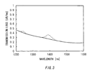
- a dotted line shows a spectrum of the transmission loss in case that the optical fiber, the OH peak of which is sufficiently small as shown by a solidline, is exposed to atmosphere of 1% hydrogen for four days.
- Fig.3 shows a rise of 0.1dB/km of the OH peak at wavelength of about 1385nm.
- the OH peak at wavelength of about 1240nm is caused by hydrogen diffusing in the optical fiber.
- the OH peak disappears if the optical fiber is exposed to atmospheric air for a while and hydrogen is removed from the optical fiber.
- the rise of the OH peak at wavelength of about 1385nm is irreversible and does not decrease. Therefore, the defect that causes the rise of the OH peak in the optical fiber needs to be reduced sufficiently.
- the preform of the present invention is that the maximum value V 0 [log (poise)] of radial viscosity distribution of the optical fiber is greater than 7.60[log(poise)] at the T s .
- the maximum value V 0 [log(poise)] of viscosity distribution may be greater than 7.90[log(poise)].
- the prefrom comprises a multi layer structure of which an outside area of the clad has more than two layers and has a high viscosity clad layer of which at least at one temperature viscosity is greater than viscosity of the inner clad layer of the most inside area in the outside area at the temperature T s , among the clad layers outside the inner clad layer.
- an outside low viscosity clad layer of which viscosity is smaller than V 0 at the temperature T s is the most outside of the clad.
- viscosity of surface of the preform at the temperature T s is preferably lower than V 0 .
- the clad of the outside area may be comprised of two layers, that is, an inner clad layer and a high viscosity clad layer.
- a synthetic quartz glass may be used as the inner clad layer, and a quartz glass, for example such as a native quartz or a crystallization synthetic quartz glass, containing crystal type silica may be used as the high viscosity clad layer.
- the preform may be manufactured by using the synthetic quartz glass having the lower viscosity than a pure synthetic quartz glass by doping at least with one dopant among chlorine, germanium, fluorine, and phosphorus as the inner clad layer and using the synthetic quartz glass having higher viscosity than the inner clad layer by not doping or doping with small amount of dopant as the high viscosity clad layer.
- a portion containing at least the core and the inner clad layer may be formed by VAD method, OVD method, MCVD method, and PCVD method, or by appropriate combination of them.
- a method for manufacturing the preform includes steps of covering circumference of the rod at least the core and the inner clad layer with a tube containing at least the high viscosity clad layer, and unifying the rod and the tube by heating and contracting the tube or by heating glass grain while depositing the glass grain which forms the high viscosity clad layer.
- plasma flame is preferably used at this heating.
- the preform may be manufactured by forming a porous preform by depositing glass particles generated by a flame hydrolysis of a glass crude material containing silicon on the circumference of the rod comprising at least the core and the inner clad layer, and forming the high viscosity clad layer by vitrifying the porous preform at temperature between 1400 and 1600 °C after dehydrating the porous preform in atmosphere containing dehydration gas at temperature range between 900 and 1200 °C.
- dehydration gas is used as the dehydration gas.
- the method for manufacturing preform comprises covering circumference of the rod comprising at least the core, the inner clad layer, and the high viscosity clad layer with the tube containing at least the outside low viscosity clad layer, and unifying the rod and the tube by heating and contracting the tube.
- the preform may be manufactured by forming the outside low viscosity clad layer by depositing glass particles generated by flame hydrolysis of glass crude material containing silicon on the circumference of the rod.
- the method for manufacturing the preform may comprise covering circumference of the rod comprising at least the core and the inner clad layer with the tube containing the high viscosity clad layer, and unifying the rod and the tube by heating and contracting the tube, while forming the outside low viscosity clad layer by depositing glass particles generated by flame hydrolysis of glass crude material containing silicon.
- the method may comprise covering circumference of the rod comprising at least the core and the inner clad layer with the tube containing at least the high viscosity clad layer and the outside low viscosity clad layer, and unifying the rod and the tube by heating and contracting the tube.
- the optical fiber of which the transmission loss at wavelength of 1385nm is equal to or less than 0.35dB/km, preferably equal to or less than 0.30dB/km, is obtained by heating and drawing the above-mentioned preform.
- the transmission loss of the optical fiber at wavelength of 1385nm is equal to or less than 0. 35dB/km in case that the fiber is exposed to atmosphere containing 1% hydrogen for four days, and does not substantially change compared with the transmission loss at wavelength of 1385nm before exposed to the atmosphere.
- FIG. 4 shows an example of a preform 200 manufactured by the sintering apparatus 100 shown in Fig. 1.
- a preform 200 has a cylindrical core 10, made from quartz doped with germanium, and a first, inner clad 32, made from quartz, formed around the outside surface of the core 10.
- a second, outer clad 34 may be formed around the outside surface of the preform 200 to increase the thickness of the clad 32.
- the content of the OH group in the preform 200 is substantially 0.8 ppb or less.
- the amount of projection of the OH peak in the curve that shows the transmission loss of the light of the optical fiber, which is obtained by drawing the preform 200 is substantially 0.05 dB/km or less. Therefore, the optical fiber obtained from the preform 200 can be used for light transmission in the wavelength band from 1300 nm to 1600 nm.
- the rise of the transmission loss (OH peak) at wavelength of 1385nm is suppressed by controlling radial viscosity distribution around softening temperature of the preform.
- the preform of the present invention is that the maximum value V 0 [log(poise)] of radial viscosity distribution of the optical fiber is greater than 7.60 [log (poise) ] at the temperature T s , defined as temperature at which the maximum value V 0 [log(poise)] of radial viscosity distribution of the optical fiber in an inside area is 7.60[log(poise)] in an inside and an outside area equivalent to two times of mode field diameter, in which light at wavelength of 1385nm propagates in the optical fiber obtained by drawing the preform.
- the optical fiber obtained by drawing the preform of the present invention has a superior characteristic that rise of the OH peak is suppressed remarkably without depending on the condition of the drawing process.
- This temperature T s is about 1600 °C in the case of a normal single mode fiber in which quartz glass doped with germanium (Ge), is used as a core.
- the clad is doped with a dopant to adjust a viscosity
- the viscosity of the clad becomes greater than a viscosity of the core and generally composition is substantially constant in a radial direction, the above mentioned viscosity distribution is not obtainable.
- the above-mentioned viscosity distribution is achieved by having more than two layers as the clad in the outside area, lowering viscosity of the inner clad layer of the most inside layer in the outside area, and forming a high viscosity layer by heightening viscosity of at least one of the other clad layers.
- the fiber normally has two layers including an inner clad layer of low viscosity and a high viscosity clad layer, it may have three layers as mentioned below according to viscosity and thickness of the high viscosity clad layer.
- maximum value V 0 [log(poise)] of radial viscosity distribution outside the inside area is preferably equal to or more than 7.90[log(poise)] at the temperature T s at which the maximum value of radial viscosity distribution is 7.60[log (poise)], so that the desired effect of the invention can be realized.
- outer diameter of the inner clad is preferably small to suppress rise of the OH peak due to hydrogen
- a glass used for the high viscosity clad layer is material of which the possibility of increasing the transmission loss remarkably is high like a native quartz glass
- the outer diameter is sufficiently large (about six times of the mode field diameter)
- the initial loss may be large.
- an upper limit of V 0 is about 9.0.
- an upper limit of V 0 can be larger than 9.0, and influences such as the transmission loss caused by doping, can not be defined sweepingly because the influence largely depends on the composition.
- a problem that strength of the optical fiber becomes lower may occur by residual stress of the surface of the optical fiber changing to tensile stress.
- rise of the OH peak and the initial loss are advantageously suppressed, but residual tensile stress of the surface of the optical fiber becomes large and snapping of the fiber can be caused during the drawing, winging back, or proof test.
- Viscosity can be distributed in radial direction of the preform by changing quality of glass material composing the inner clad layer and the high viscosity clad layer.
- the synthetic quartz glass used for the preform for the conventional optical fiber includes amorphous structure manufactured by oxidizing or hydrolyzing by flame glass crude material gas such as silicon tetrachloride.
- amorphous structure manufactured by oxidizing or hydrolyzing by flame glass crude material gas such as silicon tetrachloride.
- the native quartz glass manufactured by heating and fusing the native quartz there are many microcrystals of cristobalite type helix originating from the nature of quartz and quartz type helix that cristobalite type is dislocated in the amorphous structure. Because these microcrystals suppress flow of glass, the native quartz glass has higher viscosity than the synthetic quartz glass.
- a crystallization quartz glass manufactured by depositing microcrystal in the synthetic quartz glass has higher viscosity than a conventional synthetic quartz glass.
- viscosity of the crystallization quartz glass can be lower easily by doping the synthetic quartz glass with many kind of dopant.
- the dopant such as chlorine, germanium, fluorine, phosphorus, and the like does not cause so large rise of the loss at wavelength range between 1300 to 1600nm which is normally used for the optical fiber communication, so these dopant are preferably used.
- the synthetic quartz glass or the synthetic quartz glass doped with a dopant to lower viscosity is preferably used for the inner clad layer, and the inner clad layer can be formed as an extension of clad portion of the inside area.
- the first method covering outside of a rod containing the core portion and the inner clad layer with the high viscosity clad layer having high viscosity comprises unifying the rod and a tube by placing the rod in the tube containing the high viscosity clad layer and contracting the rod by heating form outside.
- oxyhydrogen flame, electric furnace, plasma torch, or the like can be used as a heating source.
- the second method comprises unifying the rod and glass grain by heating while depositing on the circumference of the above-mentioned rod by scattering the glass grain composing the high viscosity clad layer.
- plasma torch is preferably used as the heating source.
- the third method covering the rod with the high viscosity clad layer is OVD method that includes forming the porous preform by depositing glass particles manufactured by flame hydrolysis of the glass crude material containing silicon on the circumference of the above-mentioned rod, and a dehydrating porous preform at the temperature range between 900 and 1200 °C in the atmosphere containing dehydration gas such as chlorine or the like, and then forming the high viscosity clad layer by vitrifying in the atmosphere at the temperature between 1400 and 1600 °C.
- the inner clad layer needs to be doped with dopant to lower its viscosity.
- the first method covering outside of the high viscosity clad layer with the outside low viscosity clad layer includes covering the circumference of the rod with the tube containing at least the outside low viscosity clad layer, and unifying the rod and the tube by heating and contracting the tube.
- the second method covering outside of the high viscosity clad layer with the outside low viscosity clad layer includes depositing glass particles manufactured by flame hydrolysis of glass crude material containing silicon on the circumference of the rod containing the high viscosity clad layer.
- the first method covering outside of the inner clad layer with the high viscosity clad layer and the outside low viscosity clad layer comprises covering the circumference of the rod comprising at least the core and the inner clad layer with the tube containing the high viscosity clad layer, and then covering the tube with the outside low viscosity clad layer by depositing glass particles manufactured by flame hydrolysis of glass crude material containing silicon, while unifying the rod and the tube by heating and contracting the tube.
- the first method covering outside of the inner clad layer with the high viscosity clad layer and the outside low viscosity clad layer comprises covering the circumference of the rod comprising at least the core and the inner clad layer with the tube containing at least the high viscosity clad layer and the outside low viscosity clad layer, and unifying the rod and the tube by heating and contracting the tube.
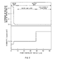
- An step index type single mode optical fiber as shown in Fig.5, of which outer diameter is 125 ⁇ m, difference of relative index of refraction is 0.34%, mode field diameter at wavelength of 1385nm is 10 ⁇ m, is manufactured by forming clad of periphery of the core in inside area with glass which has the same composition as the inner clad layer in outside area, and drawing the preform having two layers of the inner clad layer and the high viscosity clad layer in outside area at drawing speed of 800m/min and drawing tension of 1.4N.
- an outer diameter of the inner clad layer is 100 ⁇ m in terms of optical fiber diameter
- thickness of the high viscosity clad layer is 12.5 ⁇ m in terms of optical fiber
- viscosity V 0 of the high viscosity clad layer at the temperature T s is 7.9 [log(poise)] .
- Rise of the OH peak of 0.03dB/km is measured, after this optical fiber is exposed to atmosphere containing 1% hydrogen for four days.
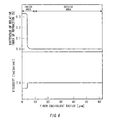
- Figs. 5 to 7 are graphs showing relationships of differences of relative index of refraction and radial viscosity distribution at the temperature T s of the preform, of which upper row is relationship of difference of relative index of refraction and structure, and the lower is relationship of viscosity and optical fiber equivalent radius.
- the step index type single mode optical fiber as shown in Fig.5, of which outer diameter is 125 ⁇ m, difference of relative index of refraction is 0.34%, mode field diameter at wavelength of 1385nm is 10 ⁇ m, is manufactured by forming clad of periphery of the core in the inside area with glass which has the same composition as the inner clad layer in outside area, and drawing the preform having two layers of the inner clad layer and the high viscosity clad layer in outside area at drawing speed of 800m/min and drawing tension of 1.4N.
- an outer diameter of the inner clad layer is 90 ⁇ m in terms of optical fiber diameter
- thickness of the high viscosity clad layer is 17.5 ⁇ m in terms of optical fiber
- viscosity V 0 of the high viscosity clad layer at the temperature T s is 7.9[log(poise)].
- Rise of the OH peak of 0.014dB/km is measured, after this optical fiber is exposed to atmosphere containing 1% hydrogen for four days.
- the step index type single mode optical fiber as shown in Fig.5, of which outer diameter is 125 ⁇ m, difference of relative index of refraction is 0.34%, mode field diameter at wavelength of 1385nm is 10 ⁇ m, is manufactured by forming clad of periphery of the core in inside area with glass which has the same composition as the inner clad layer in outside area, and drawing the preform having two layers of the inner clad layer and the high viscosity clad layer in outside area at drawing speed of 800m/min and drawing tension of 1.4N.
- an outer diameter of the inner clad layer is 80 ⁇ m in terms of optical fiber diameter
- thickness of the high viscosity clad layer is 22.5 ⁇ m in terms of optical fiber
- viscosity V 0 of the high viscosity clad layer at the temperature T s is 7.9[log(poise)].
- the step index type single mode optical fiber as shown in Fig.5, of which outer diameter is 125 ⁇ m, difference of relative index of refraction is 0.34%, mode field diameter at wavelength of 1385nm is 10 ⁇ m, is manufactured by forming clad of periphery of the core in inside area with glass which has the same composition as the inner clad layer in outside area, and drawing the preform having two layers of the inner clad layer and the high viscosity clad layer in outside area at drawing speed of 800m/min and drawing tension of 1.4N.
- an outer diameter of the inner clad layer is 35 ⁇ m in terms of optical fiber diameter
- thickness of the high viscosity clad layer is 45 ⁇ m in terms of optical fiber
- viscosity V 0 of the high viscosity clad layer at the temperature T s is 7.9[log(poise)].
- the step index type single mode optical fiber as shown in Fig.5, of which outer diameter is 125 ⁇ m, difference of relative index of refraction is 0.34%, mode field diameter at wavelength of 1385nm is 10 ⁇ m, is manufactured by forming clad of periphery of core in inside area with glass which has the same composition as the inner clad layer in outside area, and drawing the pre-form having two layers of the inner clad layer and the high viscosity clad layer in outside area at drawing speed of 800m/min and drawing tension of 1.4N.
- an outer diameter of the inner clad layer is 80 ⁇ m in terms of optical fiber diameter
- thickness of the high viscosity clad layer is 22.5 ⁇ m in terms of optical fiber
- viscosity V 0 of the high viscosity clad layer at the temperature T s is 8.5[log(poise)].
- the step index type single mode optical fiber as shown in Fig.6, of which outer diameter is 125 ⁇ m, difference of relative index of refraction is 0.34%, mode field diameter at wavelength of 1385nm is 10 ⁇ m, is manufactured by drawing a normal pre-form that the whole of clad is formed with the same material as clad of periphery of the core at drawing speed of 800m/min and drawing tension of 1.4N.
- the step index type single mode optical fiber as shown in Fig.5, of which outer diameter is 125 ⁇ m, difference of relative index of refraction is 0.34%, mode field diameter at wavelength of 1385nm is 10 ⁇ m, is manufactured by forming clad of periphery of core in inside area with glass which has the same composition as the inner clad layer in outside area, and drawing the pre-form having two layers of the inner clad layer and the high viscosity clad layer in outside area at drawing speed of 500m/min and drawing tension of 1.4N.
- an outer diameter of the inner clad layer is 100 ⁇ m in terms of optical fiber diameter
- thickness of the high viscosity clad layer is 12.5 ⁇ m in terms of optical fiber
- viscosity V 0 of the high viscosity clad layer at the temperature T s is 7.9[log(poise)].
- Rise of the OH peak of 0.011dB/km is measured, after this optical fiber is exposed to atmosphere containing 1% hydrogen for four days.
- the step index type single mode optical fiber as shown in Fig.6, of which outer diameter is 125 ⁇ m, difference of relative index of refraction is 0.34%, mode field diameter at wavelength of 1385nm is 10 ⁇ m, is manufactured by drawing the normal optical fiber pre-form that the whole of clad is formed with the same material as clad of periphery of the core at drawing speed of 500m/min and drawing tension of 1.4N.
- the step index type single mode optical fiber as shown in Fig.5, of which outer diameter is 125 ⁇ m, difference of relative index of refraction is 0.34%, mode field diameter at wavelength of 1385nm is 10 ⁇ m, is manufactured by forming clad of periphery of core in inside area with glass which has the same composition as the inner clad layer in outside area, and drawing the pre-form having two layers of the inner clad layer and the high viscosity clad layer in outside area at drawing speed of 150m/min and drawing tension of 1.4N.
- an outer diameter of the inner clad layer is 100 ⁇ m in terms of optical fiber diameter
- thickness of the high viscosity clad layer is 12.5 ⁇ m in terms of optical fiber
- viscosity V 0 of the high viscosity clad layer at the temperature T s is 7.9[log(poise)].
- the step index type single mode optical fiber as shown in Fig.6, of which outer diameter is 125 ⁇ m, difference of relative index of refraction is 0.34%, mode field diameter) at wavelength of 1385nm is 10 ⁇ m, is manufactured by drawing the normal optical fiber pre-form that the whole of clad is formed with the same material as clad of periphery of the core at drawing speed of 150m/min and drawing tension of 1.4N.
- the step index type single mode optical fiber as shown in Fig.7 of which outer diameter is 125 ⁇ m, difference of relative index of refraction is 0.34%, mode field diameter at wavelength of 1385nm is 10 ⁇ m, is manufactured by forming clad of periphery of core in inside area with glass which has the same composition as the inner clad layer in outside area, and drawing the pre-form having three layers of the inner clad layer, the high viscosity clad layer, and the outside low viscosity clad layer in outside area at drawing speed of 800m/min and drawing tension of 1.4N.
- an outer diameter of the inner clad layer is 105 ⁇ m in terms of optical fiber diameter
- thickness of the high viscosity clad layer is 7 ⁇ m in terms of optical fiber
- thickness of the outside low viscosity clad layer is 3 ⁇ m in terms of optical fiber
- viscosity V 0 of the high viscosity clad layer at the temperature T s is 8.5 [log (poise)]
- viscosity V t of the outside low viscosity clad layer at the temperature T s is 7 . 6 [log (poise) ] .
- 1% proof test on the optical fiber is conducted, but no disconnection of fiber is found. Furthermore after this optical fiber is exposed to atmosphere containing 1% hydrogen for four days, rise of the OH peak is measured, but no rise is recognized at all.
- the reason why there are no disconnection of the fiber regardless of thickness of the high viscosity clad layer of 7 ⁇ m is because the outside low viscosity clad layer is formed the most outside of the clad.
- the step index type single mode optical fiber as shown in Fig.5, of which outer diameter is 125 ⁇ m, difference of relative index of refraction is 0.34%, mode field diameter at wavelength of 1385nm is 10 ⁇ m, is manufactured by forming clad of periphery of core in inside area with glass which has the same composition as the inner clad layer in outside area, and drawing the pre-form having two layers of the inner clad layer and the high viscosity clad layer in outside area at drawing speed of 800m/min and drawing tension of 1.4N.
- an outer diameter of the inner clad layer is 111 ⁇ m in terms of optical fiber diameter
- thickness of the high viscosity clad layer is 7 ⁇ m in terms of optical fiber
- viscosity V0 of the high viscosity clad layer at the temperature Ts is 8.5 [log (poise) ] .
- the optical fiber breaks, and many breakage inside of remaining optical fiber are also recognized. Because the outside low viscosity clad layer is not formed on the most outside of the clad, the optical fiber is broken.
- the OH peak in the fiber at wavelength about 1385nm hardly rises regardless of condition of drawing.
Landscapes
- Chemical & Material Sciences (AREA)
- Engineering & Computer Science (AREA)
- Physics & Mathematics (AREA)
- Organic Chemistry (AREA)
- Geochemistry & Mineralogy (AREA)
- Life Sciences & Earth Sciences (AREA)
- Materials Engineering (AREA)
- Manufacturing & Machinery (AREA)
- General Life Sciences & Earth Sciences (AREA)
- Optics & Photonics (AREA)
- Chemical Kinetics & Catalysis (AREA)
- General Chemical & Material Sciences (AREA)
- General Physics & Mathematics (AREA)
- Thermal Sciences (AREA)
- Manufacture, Treatment Of Glass Fibers (AREA)
- Glass Compositions (AREA)
- Surface Treatment Of Glass Fibres Or Filaments (AREA)
Applications Claiming Priority (2)
| Application Number | Priority Date | Filing Date | Title |
|---|---|---|---|
| JP2002230380A JP4093553B2 (ja) | 2002-08-07 | 2002-08-07 | 光ファイバプリフォームとその製造方法、及びこれを線引きして得られる光ファイバ |
| JP2002230380 | 2002-08-07 |
Publications (3)
| Publication Number | Publication Date |
|---|---|
| EP1388525A2 true EP1388525A2 (fr) | 2004-02-11 |
| EP1388525A3 EP1388525A3 (fr) | 2006-03-29 |
| EP1388525B1 EP1388525B1 (fr) | 2012-12-05 |
Family
ID=30437755
Family Applications (1)
| Application Number | Title | Priority Date | Filing Date |
|---|---|---|---|
| EP03090239A Expired - Lifetime EP1388525B1 (fr) | 2002-08-07 | 2003-07-30 | Procédé de fabrication d'une préforme pour fibres optiques et la préforme et la fibre optique capables d'être obtenues par le procédé |
Country Status (7)
| Country | Link |
|---|---|
| US (2) | US20040028362A1 (fr) |
| EP (1) | EP1388525B1 (fr) |
| JP (1) | JP4093553B2 (fr) |
| KR (1) | KR100982765B1 (fr) |
| CN (1) | CN1495135B (fr) |
| CA (1) | CA2436178A1 (fr) |
| TW (1) | TW200402401A (fr) |
Cited By (5)
| Publication number | Priority date | Publication date | Assignee | Title |
|---|---|---|---|---|
| FR2863606A1 (fr) * | 2003-12-15 | 2005-06-17 | Cit Alcatel | Procede de realisation d'une preforme a fibre optique, preforme a fibre optique et fibre optique associees |
| EP1466873A3 (fr) * | 2003-04-08 | 2011-01-05 | Shin-Etsu Chemical Co., Ltd. | Préforme en verre pour fibres optiques et procédé de sa fabrication |
| WO2012163644A1 (fr) * | 2011-05-27 | 2012-12-06 | J-Plasma Gmbh | Procédé de fabrication d'un demi-produit destiné à la fabrication d'une fibre optique optimisée en flexion |
| US20220267192A1 (en) * | 2019-07-17 | 2022-08-25 | Heraeus Quarzglas Gmbh & Co. Kg | Methods for producing a hollow-core fiber and for producing a preform for a hollow-core fiber |
| DE102011110247B4 (de) * | 2011-05-27 | 2026-02-12 | J-Fiber Gmbh | Verfahren zur Herstellung eines Halbzeugs zur Fertigung einer biegeoptimierten Lichtleitfaser |
Families Citing this family (13)
| Publication number | Priority date | Publication date | Assignee | Title |
|---|---|---|---|---|
| US7911943B2 (en) * | 2006-01-13 | 2011-03-22 | Nokia Corporation | Optimization of PDP context usage |
| EP2008977B1 (fr) * | 2006-06-26 | 2013-09-25 | Sumitomo Electric Industries, Ltd. | Procede de fabrication d'une fibre optique et sa preforme |
| DE102007003889B3 (de) * | 2007-01-19 | 2008-09-11 | Heraeus Quarzglas Gmbh & Co. Kg | Quarzglasrohr als Halbzeug für die Vorform- und Faserherstellung, dessen Verwendung sowie Verfahren zur Herstellung des Quarzglasrohres |
| JP4926164B2 (ja) * | 2008-12-26 | 2012-05-09 | 信越化学工業株式会社 | 高周波誘導熱プラズマトーチを用いた光ファイバプリフォームの製造方法及び装置 |
| US8065893B2 (en) | 2009-07-10 | 2011-11-29 | Dau Wu | Process, apparatus, and material for making silicon germanium core fiber |
| US8488932B2 (en) * | 2010-02-26 | 2013-07-16 | Corning Incorporated | Optical fiber with increased mechanical strength |
| US9108876B2 (en) * | 2011-11-30 | 2015-08-18 | Corning Incorporated | Pressed, multilayered silica soot preforms for the manufacture of single sinter step, complex refractive index profile optical fiber |
| US9290405B2 (en) | 2013-09-06 | 2016-03-22 | Corning Incorporated | Method of making updoped cladding by using silicon tertrachloride as the dopant |
| US9658395B2 (en) * | 2014-10-21 | 2017-05-23 | Ofs Fitel, Llc | Low loss optical fiber and method of making the same |
| US9772445B2 (en) * | 2015-04-07 | 2017-09-26 | Corning Incorporated | Low attenuation fiber with stress relieving layer and a method of making such |
| PL3601175T3 (pl) | 2017-03-29 | 2024-04-29 | Prysmian S.P.A. | Sposób i urządzenie do suszenia i konsolidacji preformy dla światłowodów |
| WO2020157766A1 (fr) * | 2019-01-29 | 2020-08-06 | Sterlite Technologies Limited | Particules de cœur optimisées de préforme de fibre optique et préforme de fibre optique associée |
| EP3766850B1 (fr) * | 2019-07-17 | 2026-02-11 | Heraeus Quarzglas GmbH & Co. KG | Procédé de fabrication d'une fibre à coeur creux et de fabrication d'une préforme pour fibre à coeur creux |
Family Cites Families (33)
| Publication number | Priority date | Publication date | Assignee | Title |
|---|---|---|---|---|
| US30883A (en) * | 1860-12-11 | Improvement in corn-planters | ||
| CH620181A5 (en) * | 1975-08-16 | 1980-11-14 | Heraeus Schott Quarzschmelze | Process for the preparation of synthetic quartz glass, apparatus to carry out the process, and the use of the synthetic quartz glass |
| JPS55100233A (en) * | 1979-01-23 | 1980-07-31 | Nippon Telegr & Teleph Corp <Ntt> | Production of optical fiber base material |
| JPS59202401A (ja) * | 1983-05-02 | 1984-11-16 | Sumitomo Electric Ind Ltd | 光フアイバおよびその製造方法 |
| JPS60141634A (ja) * | 1983-12-28 | 1985-07-26 | Shin Etsu Chem Co Ltd | 光フアイバ−用母材およびその製造方法 |
| JPS62191432A (ja) | 1986-02-18 | 1987-08-21 | Sumitomo Electric Ind Ltd | 低欠陥光フアイバ用プリフオ−ム |
| JPH01160840A (ja) | 1987-12-16 | 1989-06-23 | Sumitomo Electric Ind Ltd | 分散シフト光フアイバ用母材及びその製造方法 |
| DE3820217A1 (de) * | 1988-06-14 | 1989-12-21 | Rheydt Kabelwerk Ag | Lichtwellenleiter, insbesondere einmodenfaser |
| JP2988524B2 (ja) * | 1988-09-19 | 1999-12-13 | 株式会社フジクラ | 光ファイバおよびその製造方法 |
| EP0413387A1 (fr) * | 1989-08-16 | 1991-02-20 | Koninklijke Philips Electronics N.V. | Fibre optique en mode simple maintenant la polarisation |
| GB9010943D0 (en) * | 1990-05-16 | 1990-07-04 | British Telecomm | Wave-guiding structure with lasing properties |
| FR2679548B1 (fr) * | 1991-07-25 | 1994-10-21 | Alsthom Cge Alcatel | Procede de fabrication de fibres optiques actives. |
| US6205268B1 (en) * | 1993-05-28 | 2001-03-20 | Lucent Technologies Inc. | Arrangement of optical fiber segments for minimizing effect of nonlinearities |
| EP0656325B1 (fr) * | 1993-11-29 | 1999-09-22 | AT&T Corp. | Procédé de fabrication de préformes pour fibres optiques |
| KR0162604B1 (ko) * | 1994-10-07 | 1999-04-15 | 김광호 | 광 섬유 모재 제조 방법 |
| JP3596080B2 (ja) * | 1995-04-17 | 2004-12-02 | 住友電気工業株式会社 | 光ファイバ型回折格子作製用光ファイバ母材の製造方法 |
| CN1087432C (zh) * | 1995-08-31 | 2002-07-10 | 住友电气工业株式会社 | 色散补偿光纤及其制造方法 |
| JP3845906B2 (ja) * | 1996-08-09 | 2006-11-15 | 住友電気工業株式会社 | 合成シリカガラスの製造方法 |
| FR2760449B1 (fr) * | 1997-03-06 | 1999-04-16 | Alcatel Fibres Optiques | Procede pour purifier de la silice naturelle ou synthetique et application au depot de silice naturelle ou synthetique purifiee sur une preforme de fibre optique |
| US6131415A (en) * | 1997-06-20 | 2000-10-17 | Lucent Technologies Inc. | Method of making a fiber having low loss at 1385 nm by cladding a VAD preform with a D/d<7.5 |
| FR2774678B1 (fr) * | 1998-02-12 | 2000-03-03 | Alsthom Cge Alcatel | Procede de recharge d'une preforme de fibre optique a l'aide de grains de silice dopes en aluminium |
| DE19850736C2 (de) * | 1998-11-04 | 2003-04-17 | Heraeus Tenevo Ag | Kernglas für eine Vorform für eine optische Faser, unter Verwendung des Kernglases hergestellte Vorform, sowie Verfahren zur Herstellung des Kernglases einer Vorform für eine optische Faser |
| JP4079204B2 (ja) * | 1998-11-09 | 2008-04-23 | 信越石英株式会社 | 光ファイバ母材用石英ガラス管及びその製造方法 |
| DE19852704A1 (de) * | 1998-11-16 | 2000-05-18 | Heraeus Quarzglas | Verfahren zur Herstellung einer Vorform für eine optische Faser und für die Durchführung des Verfahrens geeignetes Substratrohr |
| KR100334820B1 (ko) | 1999-07-22 | 2002-05-02 | 윤종용 | 분산제어 광섬유 및 그 대구경 모재의 제조 방법 |
| JP4237357B2 (ja) | 1999-10-08 | 2009-03-11 | 信越化学工業株式会社 | 変形第1クラッドを有する光ファイバ母材の製造方法及び光ファイバ母材並びに光ファイバ |
| JP4345180B2 (ja) * | 2000-03-10 | 2009-10-14 | 住友電気工業株式会社 | 光ファイバ母材製造方法、光ファイバ母材および光ファイバ製造方法 |
| JP4024461B2 (ja) * | 2000-07-14 | 2007-12-19 | 富士通株式会社 | 分散補償光ファイバ |
| TWI226464B (en) * | 2000-11-13 | 2005-01-11 | Sumitomo Electric Industries | Optical fiber, non-linear optical fiber, optical amplifier using the same optical fiber, wavelength converter and optical fiber manufacture method |
| FR2823198B1 (fr) * | 2001-04-09 | 2003-07-04 | Cit Alcatel | Procede de fabrication de preformes a grande capacite par mcvd |
| US20030024276A1 (en) * | 2001-05-30 | 2003-02-06 | 3M Innovative Properties Company | Method of manufacture of an optical waveguide article including a fluorine-containing zone |
| US6776012B2 (en) * | 2001-06-26 | 2004-08-17 | Fitel Usa Corp. | Method of making an optical fiber using preform dehydration in an environment of chlorine-containing gas, fluorine-containing gases and carbon monoxide |
| US20030077055A1 (en) * | 2001-10-19 | 2003-04-24 | Jds Uniphase Corporation | Method of fabricating optical fiber preforms with high dopant concentration and good geometry |
-
2002
- 2002-08-07 JP JP2002230380A patent/JP4093553B2/ja not_active Expired - Fee Related
-
2003
- 2003-07-29 CA CA002436178A patent/CA2436178A1/fr not_active Abandoned
- 2003-07-29 TW TW092120615A patent/TW200402401A/zh unknown
- 2003-07-30 EP EP03090239A patent/EP1388525B1/fr not_active Expired - Lifetime
- 2003-08-01 KR KR1020030053381A patent/KR100982765B1/ko not_active Expired - Fee Related
- 2003-08-05 CN CN031496687A patent/CN1495135B/zh not_active Expired - Fee Related
- 2003-08-06 US US10/634,779 patent/US20040028362A1/en not_active Abandoned
-
2005
- 2005-05-20 US US11/133,193 patent/US7752869B2/en not_active Expired - Fee Related
Non-Patent Citations (1)
| Title |
|---|
| None |
Cited By (7)
| Publication number | Priority date | Publication date | Assignee | Title |
|---|---|---|---|---|
| EP1466873A3 (fr) * | 2003-04-08 | 2011-01-05 | Shin-Etsu Chemical Co., Ltd. | Préforme en verre pour fibres optiques et procédé de sa fabrication |
| FR2863606A1 (fr) * | 2003-12-15 | 2005-06-17 | Cit Alcatel | Procede de realisation d'une preforme a fibre optique, preforme a fibre optique et fibre optique associees |
| EP1544174A1 (fr) * | 2003-12-15 | 2005-06-22 | Draka Comteq B.V. | Fibre optique et sa préform et procédé de fabrication de la préfrome |
| WO2012163644A1 (fr) * | 2011-05-27 | 2012-12-06 | J-Plasma Gmbh | Procédé de fabrication d'un demi-produit destiné à la fabrication d'une fibre optique optimisée en flexion |
| US9382149B2 (en) | 2011-05-27 | 2016-07-05 | J-Plasma Gmbh | Methods for producing a semifinished part for the manufacture of an optical fiber which is optimized in terms of bending |
| DE102011110247B4 (de) * | 2011-05-27 | 2026-02-12 | J-Fiber Gmbh | Verfahren zur Herstellung eines Halbzeugs zur Fertigung einer biegeoptimierten Lichtleitfaser |
| US20220267192A1 (en) * | 2019-07-17 | 2022-08-25 | Heraeus Quarzglas Gmbh & Co. Kg | Methods for producing a hollow-core fiber and for producing a preform for a hollow-core fiber |
Also Published As
| Publication number | Publication date |
|---|---|
| KR100982765B1 (ko) | 2010-09-16 |
| TW200402401A (en) | 2004-02-16 |
| EP1388525A3 (fr) | 2006-03-29 |
| CN1495135A (zh) | 2004-05-12 |
| EP1388525B1 (fr) | 2012-12-05 |
| KR20040014239A (ko) | 2004-02-14 |
| CN1495135B (zh) | 2011-08-31 |
| JP4093553B2 (ja) | 2008-06-04 |
| US20050229639A1 (en) | 2005-10-20 |
| CA2436178A1 (fr) | 2004-02-07 |
| JP2004067459A (ja) | 2004-03-04 |
| US7752869B2 (en) | 2010-07-13 |
| US20040028362A1 (en) | 2004-02-12 |
Similar Documents
| Publication | Publication Date | Title |
|---|---|---|
| EP1388525A2 (fr) | Procédé de fabrication d'une préforme pour fibres optiques et la préforme et la fibre optique capables d'être obtenues par le procédé | |
| US6917740B2 (en) | Optical fiber having reduced viscosity mismatch | |
| US8295668B2 (en) | Low loss optical fiber designs and methods for their manufacture | |
| EP2145218A1 (fr) | Fibre optique contenant un oxyde de metal alcalin | |
| EP0198510A1 (fr) | Procédé de fabrication d'une préforme en verre pour fibre optique | |
| US6530244B1 (en) | Optical fiber preform having OH barrier and fabrication method thereof | |
| JPH08254601A (ja) | 光を伝送するための光学的構成要素 | |
| EP1287392B1 (fr) | Fibre optique monomode et procede de fabrication correspondant | |
| US6988379B2 (en) | Method of manufacturing large capacity preforms by MCVD | |
| WO2019172197A1 (fr) | Fibre optique | |
| US6904213B2 (en) | Step index optical fiber with doped cladding and core, a preform, and a method of fabricating such a fiber | |
| KR102944739B1 (ko) | 광 파이버 | |
| US20040110007A1 (en) | Optical fiber preform having barrier layers for hydroxyl (OH) radicals | |
| US20230167002A1 (en) | Optical fibers and method of making the same | |
| CA2549319A1 (fr) | Preforme a fibre optique, methode de fabrication de cette preforme et fibre optique obtenue par etirage a partir de cette preforme | |
| JPH085856A (ja) | 石英系光ファイバとその製造方法 |
Legal Events
| Date | Code | Title | Description |
|---|---|---|---|
| PUAI | Public reference made under article 153(3) epc to a published international application that has entered the european phase |
Free format text: ORIGINAL CODE: 0009012 |
|
| AK | Designated contracting states |
Kind code of ref document: A2 Designated state(s): AT BE BG CH CY CZ DE DK EE ES FI FR GB GR HU IE IT LI LU MC NL PT RO SE SI SK TR |
|
| AX | Request for extension of the european patent |
Extension state: AL LT LV MK |
|
| PUAL | Search report despatched |
Free format text: ORIGINAL CODE: 0009013 |
|
| AK | Designated contracting states |
Kind code of ref document: A3 Designated state(s): AT BE BG CH CY CZ DE DK EE ES FI FR GB GR HU IE IT LI LU MC NL PT RO SE SI SK TR |
|
| AX | Request for extension of the european patent |
Extension state: AL LT LV MK |
|
| 17P | Request for examination filed |
Effective date: 20060515 |
|
| AKX | Designation fees paid |
Designated state(s): DE FR GB |
|
| RBV | Designated contracting states (corrected) |
Designated state(s): DE FR GB IT |
|
| 17Q | First examination report despatched |
Effective date: 20090221 |
|
| R17C | First examination report despatched (corrected) |
Effective date: 20091221 |
|
| REG | Reference to a national code |
Ref country code: DE Ref legal event code: R079 Ref document number: 60342740 Country of ref document: DE Free format text: PREVIOUS MAIN CLASS: C03B0037012000 Ipc: C03B0037014000 |
|
| GRAP | Despatch of communication of intention to grant a patent |
Free format text: ORIGINAL CODE: EPIDOSNIGR1 |
|
| RIC1 | Information provided on ipc code assigned before grant |
Ipc: G02B 6/02 20060101ALI20120521BHEP Ipc: C03C 13/04 20060101ALI20120521BHEP Ipc: G02B 6/036 20060101ALI20120521BHEP Ipc: C03B 37/014 20060101AFI20120521BHEP Ipc: C03B 37/012 20060101ALI20120521BHEP |
|
| GRAS | Grant fee paid |
Free format text: ORIGINAL CODE: EPIDOSNIGR3 |
|
| GRAA | (expected) grant |
Free format text: ORIGINAL CODE: 0009210 |
|
| AK | Designated contracting states |
Kind code of ref document: B1 Designated state(s): DE FR GB IT |
|
| REG | Reference to a national code |
Ref country code: GB Ref legal event code: FG4D |
|
| REG | Reference to a national code |
Ref country code: DE Ref legal event code: R096 Ref document number: 60342740 Country of ref document: DE Effective date: 20130131 |
|
| PLBE | No opposition filed within time limit |
Free format text: ORIGINAL CODE: 0009261 |
|
| STAA | Information on the status of an ep patent application or granted ep patent |
Free format text: STATUS: NO OPPOSITION FILED WITHIN TIME LIMIT |
|
| 26N | No opposition filed |
Effective date: 20130906 |
|
| REG | Reference to a national code |
Ref country code: DE Ref legal event code: R097 Ref document number: 60342740 Country of ref document: DE Effective date: 20130906 |
|
| PGFP | Annual fee paid to national office [announced via postgrant information from national office to epo] |
Ref country code: GB Payment date: 20140730 Year of fee payment: 12 |
|
| GBPC | Gb: european patent ceased through non-payment of renewal fee |
Effective date: 20150730 |
|
| PG25 | Lapsed in a contracting state [announced via postgrant information from national office to epo] |
Ref country code: GB Free format text: LAPSE BECAUSE OF NON-PAYMENT OF DUE FEES Effective date: 20150730 |
|
| REG | Reference to a national code |
Ref country code: FR Ref legal event code: PLFP Year of fee payment: 14 |
|
| REG | Reference to a national code |
Ref country code: FR Ref legal event code: PLFP Year of fee payment: 15 |
|
| REG | Reference to a national code |
Ref country code: FR Ref legal event code: PLFP Year of fee payment: 16 |
|
| PGFP | Annual fee paid to national office [announced via postgrant information from national office to epo] |
Ref country code: FR Payment date: 20210611 Year of fee payment: 19 Ref country code: IT Payment date: 20210610 Year of fee payment: 19 |
|
| PGFP | Annual fee paid to national office [announced via postgrant information from national office to epo] |
Ref country code: DE Payment date: 20210630 Year of fee payment: 19 |
|
| REG | Reference to a national code |
Ref country code: DE Ref legal event code: R119 Ref document number: 60342740 Country of ref document: DE |
|
| PG25 | Lapsed in a contracting state [announced via postgrant information from national office to epo] |
Ref country code: FR Free format text: LAPSE BECAUSE OF NON-PAYMENT OF DUE FEES Effective date: 20220731 |
|
| PG25 | Lapsed in a contracting state [announced via postgrant information from national office to epo] |
Ref country code: DE Free format text: LAPSE BECAUSE OF NON-PAYMENT OF DUE FEES Effective date: 20230201 |
|
| PG25 | Lapsed in a contracting state [announced via postgrant information from national office to epo] |
Ref country code: IT Free format text: LAPSE BECAUSE OF NON-PAYMENT OF DUE FEES Effective date: 20220730 |