EP1388607A2 - Procédé de teinture de lentilles en plastique et appareil de teinture - Google Patents
Procédé de teinture de lentilles en plastique et appareil de teinture Download PDFInfo
- Publication number
- EP1388607A2 EP1388607A2 EP03017384A EP03017384A EP1388607A2 EP 1388607 A2 EP1388607 A2 EP 1388607A2 EP 03017384 A EP03017384 A EP 03017384A EP 03017384 A EP03017384 A EP 03017384A EP 1388607 A2 EP1388607 A2 EP 1388607A2
- Authority
- EP
- European Patent Office
- Prior art keywords
- lens
- dyeing
- dye
- temperature
- base body
- Prior art date
- Legal status (The legal status is an assumption and is not a legal conclusion. Google has not performed a legal analysis and makes no representation as to the accuracy of the status listed.)
- Granted
Links
Images


Classifications
-
- D—TEXTILES; PAPER
- D06—TREATMENT OF TEXTILES OR THE LIKE; LAUNDERING; FLEXIBLE MATERIALS NOT OTHERWISE PROVIDED FOR
- D06P—DYEING OR PRINTING TEXTILES; DYEING LEATHER, FURS OR SOLID MACROMOLECULAR SUBSTANCES IN ANY FORM
- D06P5/00—Other features in dyeing or printing textiles, or dyeing leather, furs, or solid macromolecular substances in any form
- D06P5/003—Transfer printing
- D06P5/004—Transfer printing using subliming dyes
-
- D—TEXTILES; PAPER
- D06—TREATMENT OF TEXTILES OR THE LIKE; LAUNDERING; FLEXIBLE MATERIALS NOT OTHERWISE PROVIDED FOR
- D06P—DYEING OR PRINTING TEXTILES; DYEING LEATHER, FURS OR SOLID MACROMOLECULAR SUBSTANCES IN ANY FORM
- D06P1/00—General processes of dyeing or printing textiles, or general processes of dyeing leather, furs, or solid macromolecular substances in any form, classified according to the dyes, pigments, or auxiliary substances employed
- D06P1/0004—General aspects of dyeing
-
- D—TEXTILES; PAPER
- D06—TREATMENT OF TEXTILES OR THE LIKE; LAUNDERING; FLEXIBLE MATERIALS NOT OTHERWISE PROVIDED FOR
- D06P—DYEING OR PRINTING TEXTILES; DYEING LEATHER, FURS OR SOLID MACROMOLECULAR SUBSTANCES IN ANY FORM
- D06P1/00—General processes of dyeing or printing textiles, or general processes of dyeing leather, furs, or solid macromolecular substances in any form, classified according to the dyes, pigments, or auxiliary substances employed
- D06P1/0004—General aspects of dyeing
- D06P1/0016—Dye baths containing a dyeing agent in a special form such as for instance in melted or solid form, as a floating film or gel, spray or aerosol, or atomised dyes
-
- D—TEXTILES; PAPER
- D06—TREATMENT OF TEXTILES OR THE LIKE; LAUNDERING; FLEXIBLE MATERIALS NOT OTHERWISE PROVIDED FOR
- D06P—DYEING OR PRINTING TEXTILES; DYEING LEATHER, FURS OR SOLID MACROMOLECULAR SUBSTANCES IN ANY FORM
- D06P5/00—Other features in dyeing or printing textiles, or dyeing leather, furs, or solid macromolecular substances in any form
- D06P5/20—Physical treatments affecting dyeing, e.g. ultrasonic or electric
-
- D—TEXTILES; PAPER
- D06—TREATMENT OF TEXTILES OR THE LIKE; LAUNDERING; FLEXIBLE MATERIALS NOT OTHERWISE PROVIDED FOR
- D06P—DYEING OR PRINTING TEXTILES; DYEING LEATHER, FURS OR SOLID MACROMOLECULAR SUBSTANCES IN ANY FORM
- D06P5/00—Other features in dyeing or printing textiles, or dyeing leather, furs, or solid macromolecular substances in any form
- D06P5/20—Physical treatments affecting dyeing, e.g. ultrasonic or electric
- D06P5/2022—Textile treatments at reduced pression, i.e. lower than 1 atm
-
- D—TEXTILES; PAPER
- D06—TREATMENT OF TEXTILES OR THE LIKE; LAUNDERING; FLEXIBLE MATERIALS NOT OTHERWISE PROVIDED FOR
- D06P—DYEING OR PRINTING TEXTILES; DYEING LEATHER, FURS OR SOLID MACROMOLECULAR SUBSTANCES IN ANY FORM
- D06P5/00—Other features in dyeing or printing textiles, or dyeing leather, furs, or solid macromolecular substances in any form
- D06P5/20—Physical treatments affecting dyeing, e.g. ultrasonic or electric
- D06P5/2022—Textile treatments at reduced pression, i.e. lower than 1 atm
- D06P5/2033—Textile treatments at reduced pression, i.e. lower than 1 atm during dyeing
Definitions
- the present invention relates to a dyeing method of dyeing a plastic lens and a dyeing device.
- This dip dyeing method includes the steps of: preparing a dyeing solution by mixing disperse dyes of primary colors of red, blue, and yellow at a predetermined ratio and dispersing the mixture in water; heating the dyeing solution to about 90°C; and dipping a plastic lens into the heated solution, thereby dyeing the lens.
- a vapor deposition dyeing method which is for example disclosed in U.S. Patent No. 6,520,999 (Japanese patent unexamined publication No. 2001-59950).
- This method includes heating a sublimatable dye under vacuum to sublimate and vapor deposit the sublimed dye onto a lens which is heated simultaneously under vacuum, thereby dyeing the lens.
- a lens made of a material hard to dye by the conventional dip dyeing method can also be dyed and additionally working conditions can extremely be improved.
- a hard-coating treatment is well known to enhance the surface strength (hardness) of a lens.
- Such hard-coated lens is desired to be dyed by the vapor deposition dyeing method.
- the present invention has been made in view of the above circumstances and has an object to overcome the above problems and to provide a method of dyeing a plastic lens with stable reproducibility in color density even where dyeing operations are repeated, and a dyeing device.
- Another object of the present invention is providing a method of dyeing a hard-coated plastic lens.
- a dyeing method of a plastic lens including the steps of: placing the lens in a vacuum vapor deposition device; placing a base body for dyeing in the vapor deposition device, the base body having a dye application area in which a sublimatable dye is applied, so that the dye application area faces a surface of the lens to be dyed; and heating the base body in the vapor deposition device under almost a vacuum, while restraining a rise in temperature of the lens, to sublimate the dye, depositing the sublimed dye on the lens.
- a dyeing device for dyeing a plastic lens including a lens placing unit for placing the lens in the dyeing device; a base body placing unit for placing a base body for dyeing in the device, the base body having a dye application area in which a sublimatable dye is applied, so that the dye application area faces a surface of the lens to be dyed; a pump for producing almost a vacuum in the device; a heating unit for heating the base body placed in the device to sublimate the dye, depositing the sublimed dye on the lens; and a cooling unit for cooling the device to restrain the temperature rise of the lens.
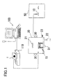
- Fig. 1 is a schematic structural view of a plastic lens dyeing system in the present embodiment.
- Fig. 2 is a flowchart showing the flow of dyeing
- a print base body 1 to be used for dyeing a plastic lens 10 (hereinafter, simply referred to as a lens) is produced.
- a sublimatable dye (a dyeing solution) is printed or applied.
- sublimatable dye which contains a dissolved or fine-grained dispersed sublimatable dye
- four dispersion dye inks of red, blue, yellow, and black if needed. These inks are separately filled in ink cartridges for an ink jet printer. The cartridges are set in an ink jet printer 110.
- the print base body 1 is made by use of a personal computer (PC) 100 and the printer 110.
- the PC 100 is used to regulate the hue and density (which are hereinafter referred all together to as "color") to be printed.
- the color is regulated by use of a drawing software, a CCM (computer color matching), or the like, on the PC 100. Accordingly, data on the desired color can be stored in the PC 100 so that the base body 1 with the same color can be repeatedly produced as needed.
- PC personal computer
- CCM computer color matching
- a print sheet 3 which forms the base body 1 is set in the printer 110.
- the PC 100 is then operated to carry out printing based on the preset data on the desired color.
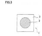
- a circular colored layer 2 which is an area applied with the dye is printed as shown in Fig. 3.
- the diameter of the colored layer 2 is preferably determined to be larger than the diameter of a surface of the lens 10 to be dyed. If the diameter of the colored layer 2 is shorter than the surface of the lens 10 to be dyed, there is a possibility that the entire surface of the lens 10 could not be sufficiently dyed.
- the print sheet 3 used for the production of the base body 1 is a sheet having an entirely black-colored back face (on which no colored layer is printed) for the purpose of enhancing the efficiency of heat absorption.
- Fig. 4 shows a schematic structural view of a vacuum vapor deposition transfer device (hereinafter, referred to as a vapor deposition device) 20 .
- a casing of the vapor deposition device 20 is made of a material with good thermal conductivity, for example, aluminum.
- the device 20 is provided at its front with a door not shown which is opened/closed for allowing insertion/removal of the plastic lens 10, the base body 1, and others.
- a heating lamp 21 serving as a heating source to heat the base body 1 to thereby sublimate the dye is disposed in an upper place.
- the lamp 21 in the present embodiment is a halogen lamp, but not limited thereto. Any lamps capable of heating the base body 1 in noncontact relation therewith may be used.
- Numeral 22 is a rotary pump which is used tc produce almost a vacuum in the vapor deposition device 20.
- Numeral 23 is a leak valve which is opened to admit outside air into the device 20, thereby returning almost the vacuum in the device 20 to atmospheric pressure.
- Numeral 30 is a cooler mounted circumferentially on the external wall of the vapor deposition device 20 in contact relation therewith. In this cooler 30, cooling water maintained at a predetermined temperature is circulated.
- Numeral 31 is a temperature sensor disposed on the bottom of the external wall of the vapor deposition device 20.
- Numeral 32 is a controller. The temperature sensor 31 detects the temperature of the external wall of the device 20 and the controller 32 sequentially monitors changes in the temperature. When the detected temperature reaches a predetermined temperature (30°C in the present embodiment), the controller 32 drives the cooler 30 to restrain a rise in the temperature of the vapor deposition device 20 by heat exchange so as not to allow the temperature rise to more than the predetermined temperature. The controller 32 further controls a display not shown to display the temperature of the external wall.
- the temperature of the vapor deposition device 20 would become gradually higher when the device 20 is continuously used to dye lenses in succession.
- the lens 10 When the lens 10 is put in the device 20 in such state the lens 10 would be influenced by the ambient temperature and therefore the temperature of the lens 10 itself would rise before a dyeing operation (herein, before turn-on of the lamp 21).
- an increase in temperature of the vapor deposition device 20 is restrained to prevent the temperature of the lens 10 from rising before the dyeing operation, thereby achieving stable dyeing reproducibility.
- the temperature of the lens 10 is preferably controlled to a temperature at which color density can be produced within a predetermined color difference with respect to the desired color density.
- the temperature of the lens 10 is preferably brought to 70°C or less, more preferably, 50"C or less. If the temperature of the lens 10 exceeds 70"C, it becomes difficult to produce the color density within a predetermined color difference with respect to the desired color density. It is to be noted that the upper limit of such temperature somewhat varies with the property of a sublimatable dye to be used.
- the temperature of the lens 10 is controlled to bring the upper limit to 70°C or less, but not limited thereto.
- the temperature of the lens 10 may be controlled to be kept at a constant temperature. The higher the temperature of the lens 10 before the dyeing operation, the more likely a difference in color density occurs due to a difference in temperatures of the lens 10 before and in the dyeing operation. Therefore, it is preferable to control the temperature of the lens 10 so as to be as low as possible and fall within a predetermined temperature difference.
- the cooler 30 is mounted on the external wall of the vapor deposition device 20, but not limited thereto. Any structure capable of preventing a rise in the temperature of the lens 10 placed inside the vapor deposition device 20 may be adapted.
- the cooler 30 may be installed on the internal wall of the vapor deposition device 20.
- Numeral 15 is a dyeing jig for placing the lens 10 and the base body 1 in the vapor deposition device 20 so that the lens surface to be dyed and the colored layer 2 are held facing each other in noncontact relation.
- Numeral 13 is a cylindrical support for supporting the base body 1. This support 13 is placed in the vapor deposition device 20 so that a lens support 11 is positioned inside the support 13.
- Numeral 12 is a lens holder for holding the lens 10 on the lens support 11
- Numeral 14 is a retainer which presses the base body 1 against the base body support 13. Thus, the base body 1 put on the support 13 is securely held between the support 13 and the retainer 14.
- the distance between the geometric center of the target surface of the lens 10 to be dyed and the base body 1 is set at preferably about 1 mm to 30 mm, more preferably about 5 mm to 20 mm.
- the base body 1 and the lens 10 are set in the jig 15 previously placed in the vapor deposition device 20 (alternatively, the jig 15 in which the base body 1 and the lens 10 are set in advance may be put in the device 20).
- the pump 22 is then operated to produce almost a vacuum in the vapor deposition device 20.
- This vacuum is produced by reducing the pressure in the device 20 to about 0.1 to 10 kPa.
- the vacuum may be below 0.1 kPa, but it will require a high-powered exhauster.
- the lamp 21 When the pressure in the vapor deposition device 20 is reduced to a predetermined pressure, the lamp 21 is turned on to heat the base body 1 from above, thereby sublimating the dye. If the heating temperature on the base body 1 is below 100°C, the dye will be hard to sublimate. If the heating temperature exceeds 300°C, the dye will be more apt to change in quality. Accordingly, the heating temperature is preferably determined in a range of 100 to 300°C.
- the heating time is preferably as short as possible. This is because the temperature of the lens 10 is more increased as the heating time is longer, so that the color reproducibility becomes unstable. Consequently, the heating time is preferably within 5 min., more preferably, within 2 min.
- the lens 10 is put in an oven 50 and heated under normal pressures to fix or set the deposited dye on the lens 10.
- This fixation process is carried out in the following steps of, heating the lens 10 in the oven 50 at a temperature set as high as possible below a resistible temperature of the lens 10; and taken the lens 10 out of the oven 50 after a lapse of the previously determined time needed to obtain a desired color.
- the heating temperature of the oven 50 is preferably about 50°C to 150°C and the heating time is preferably about 30 min. to 2 hours.
- the material of the lens 10 is selected from a polycarbonate resin (e.g., diethylene glycol bisallyl carbonate polymer (CR-39)), a polyurethane resin, an allyl resin (e.g., allyl diglycol carbonate and its copolymer, and diallyl phthalate and its copolymer), a fumaric acid resin (e.g., benzyl fumarate copolymer), a styrene resin, a polymethyl acrylate resin, a fiber resin (e.g., cellulose propionate), etc.
- a polycarbonate resin e.g., diethylene glycol bisallyl carbonate polymer (CR-39)
- a polyurethane resin e.g., diethylene glycol bisallyl carbonate polymer (CR-39)
- an allyl resin e.g., allyl diglycol carbonate and its copolymer, and diallyl phthalate and its copolymer
- a material with a high refractive index such as a thiourethane type, a thioepoxy type, and the like, and other materials with a high refractive index which have conventionally been regarded as having low (inferior) dyeability may be used.
- a lens CR-39 was used as the lens 10.
- the sublimatable inks (dyes) were Red (Kayaron Light Red BS, Nippon Kayaku Co., Ltd.), Yellow (Kayaron Yellow AQ-LE, Nippon Kayaku Co., Ltd.), and Blue (Dianix Blue AC-E, DyStar Japan Co., Ltd.).
- the dispersant was Demol MS (Kao Corporation).
- the ink prescription was as shown in Table 1.
- Each ink (red, yellow, and blue) was agitated for 10 min. or more and then treated by an ultrasonic homogenizer.
- Each ink was sliction-filtered by use of a filter having a 1 ⁇ m particle holding ability to remove particles of a large diameter, foreign substances, etc. Pure water was added to each ink to adjust the ink density to a specified density level. Thus, each ink was finished.
- Each ink prepared as above was filled in the printer 110 (RJ-1300V2, Mutoh Industries Ltd.).
- the PC 100 and the printer 110 were used to print a circle (colored layer 2) of 95 mm in diameter on a sheet 3 (a gloss paper, Mitsubishi Paper Mills Ltd.), which is used as the base body 1.
- the print data was output at a discharge amount of 50% through each head (each color).
- a heating plate was placed under the jig 15 (the lens support 11).
- the cooler 30 was driven to control the temperature of the lens 10.
- the temperature of the lens 10 was measured by a bimetal surface thermometer.
- the dyeing operation was carried out in the following steps. After the base body 1 and the lens 10 were put in the above manner in the vapor deposition device 20, the pump 22 was operated to produce a vacuum of 1 kPa in the device 20. When a stable vacuum was produced, the lamp 21 was turned on to heat the base body 1 to sublimate the dye, thus depositing the sublimed dye on the lens 10. This heati.ng time of the base body 1 was set at 40 seconds so that the temperature on the base body 1 finally reached 250°C in 40 seconds. In the experiment 1, the temperature of the undyed lens 10 was 18.8°C before the dyeing operation. After the dyeing operation, the lens 10 was taken out and then heated in the oven 50 to fix (develop) the dye. The heating temperature of the oven 50 was set at 135°C and the heating time was 1 hour.
- the dyed lens 10 was measured by a color meter (DOT-3 (a D65-10 light source), Murakami Color Research Laboratory). The measured result is shown in Table 2, wherein L* indicates luminance (brightness), a* is a constituent element representing a hue in a range of red-green, b* is a constituent element representing a hue in a range of blue yellow, and ⁇ E * is a difference in color density (i.e., a color difference) with reference to the color density obtained in the experiment 1.
- DOT-3 a D65-10 light source
- ⁇ E * is a difference in color density (i.e., a color difference) with reference to the color density obtained in the experiment 1.
- Experiment 1 18.8 73.25 -0.15 -4.75 - Experiment 2 30.2 73.22 -0.03 -4.82 0.14 Experiment 3 49.2 73.29 -0.12 -4.76 0.05 Experiment 4 57.3 73.68 -0.01 -4.51 0.51 Experiment 5 72.1 74.10 0.02 -4.33 0.96 Experiment 6 86.0 76.73 0.09 -4.10 3.55
- the results in Table 2 show that the color density was apt to become paler (lighter) as the temperature of the lens 10 was higher during dyeing, even when the same dyeing ink was used.
- the temperature of the lens 10 is high, it is preferable to control the temperature so as not to change during dyeing so that the temperature of the lens 10 is within a predetermined temperature difference.
- a composition of a hard coating liquid to be used in the present invention includes tetrafunctional silane as a main component and, in addition, an organic silicon compound (silicide) appropriately selected from among bifunctional silane, trifunctional silane, etc. and a metal oxide sol used for increasing an index.
- an organic silicon compound silane
- the tetrafunctional silane acts to improve the hardness of the produced hard coat layer.
- the tetrafunctional silane has no free radical chain and therefore the three-dimensional crosslinking density of the hard coat layer is increased as a compounding ratio of the tetrafunctional silane in the hard coating liquid is higher. Consequently, the plastic lens with the hard coat having highly efficient abrasion-resistance would be hard to dye by the dip dyeing method.
- the lens with the hard coat can be dyed even where the hard coating liquid contains the tetrafunctional silane of an amount that the lens is hard to dye by the dip dyeing method.
- An applicable compounding ratio of the tetrafunctional silane in the present invention is 30% or less by weight with respect to a total solids content in the hard coating liquid including the metal oxide sol used for increasing the index of the hard coat.
- the dyeing method of the present invention it is possible to naturally dye a hard-coated lens which can be dyed by the dip dyeing method and also to dye even another hard-coated lens which is hard to dye by the dip dyeing method, for example, a lens having a physical property value that the hard-coated lens surface is abraded by about 6 to 19 scratches by twenty strokes of a steel wool #0000 under a load of 1.5 kg.
- the tetrafunctional silane used in the present invention is selected from among, for example, tetramethoxysilane, tetraethoxysilane, tetrapropoxysilane, tetrabutoxysilane, or the like.
- the trifunctional silane is selected from among, for example, the trifunctional silane having a glycidyl group such as glycidoxy methyl trimethoxysilane, glycidoxy methyl triethoxysilane, glycidoxy methyl tripropoxysilane, ⁇ -glycidoxy ethyl trimethoxysilane, ⁇ -glycidoxy ethyl triethoxysilane, ⁇ -glycidoxy ethyl trimethoxysilane, ⁇ -glycidoxy ethyl triethoxysilane, ⁇ -glycidoxy ethyl tripropoxysilane, ⁇ -glycidoxy propyl trimethoxysilane, ⁇ -glycidoxy propyl triethoxysilane, ⁇ -glycidoxy propyl tripropoxysilane, ⁇ -glycidoxy propyl trimethoxysilane, ⁇ -glycidoxy propyl
- the bifunctional silane is selected from among, for example, glycidoxy methyl methyl dimethoxysilane, glycidoxy methyl methyl diethoxysilane, glycidoxy methyl methyl dipropoxysilane, glycidoxy methyl ethyl dimethoxysilane, glycidoxy methyl ethyl diethoxysilane, glycidoxy methyl ethyl dipropoxysilane, ⁇ -glycidoxy ethyl methyl dimethoxysilane, ⁇ -glycidoxy ethyl methyl dimethoxysilane, ⁇ -glycidoxy ethyl methyl diethoxysilane, ⁇ -glycidoxy ethyl methyl diethoxysilane, ⁇ -glycidoxy ethyl methyl diethoxysilane, ⁇ -glycidoxy ethyl methyl dipropoxysilane, ⁇ -glycid
- a single kind or two or more kinds can be selected to be used for the composition of the hard coating liquid which is used in the present invention.
- the composition of the hard coat of the present invention contains a metal-oxide sol in order to increase an index of the hard coat.
- This metal oxide sol is made by dispersing, in a colloidal state, one or more kinds of metal oxide selected from among SiO 2 , Al 2 O 3 , SnO 2 , TiO 2 , ZrO 2 , Fe 2 O 3 , ZnO, In 2 O 3 , etc. into solvent such as water, alcohol, etc.
- composition of the hard coat in the present invention may additionally contains as needed, in addition to the above components, a curing catalyst, a surface active agent, an anti-oxidizing agent, an ultraviolet absorbing agent, a light stabilizer, a pigment, a dye, and the like in slight amounts to improve an application property, liquid quality, coating quality, and others of the hard coating compositions.
- the base material (plastic lens) to which the hard coating composition of the present invention is applied may be a plastic base material generally used for spectacle lenses, for example, polymethyl methacrylate (PMMA), polycarbonate, polythiourethane, etc.
- the method of forming the hard coat on the plastic lens may be a well known method, for example, brush coating, dipping, spray painting, and spin coating.
- the temperature during .the preparation of the hard coating composition is preferably controlled to be low (30"C or less). It is further preferable to agitate the materials in a vessel slowly, without increasing the agitating speed, so as to cause the materials to react slowly.
- a hard coating liquid was prepared as below to form a hard coat layer on a plastic lens. 118 parts by weight of tetraethoxysilane and 118 parts by weight of ⁇ -glycidoxy propyl trimethoxysilane were put in a reaction vessel, and 118 parts by weight of methanol was added as solvent. This mixture was agitated at room temperatures for 2 hours.
- a TiO 2 sol (Optlake 1120F, Catalysts & Chemicals Ind. Co., Ltd.) was added as the metal oxide sol and agitated at room temperatures for 2 hours.
- the hard coating composition was produced.
- the produced hard coating composition was applied to a thiourethane plastic lens (MR-8) of a 1.60 refractive index by the dipping method.
- MR-8 thiourethane plastic lens
- the lens has previously been subjected to surface treatment by alkali cleaning or plasma treatment.
- the lens was dipped into the hard coating composition to form a coat at a pull-up speed of 600 mm/min.
- the lens with the coat was preliminarily dried at 80°C for 5 m.in. and finally dried at 120°C for 1 hour, thus completing a hard coated lens.
- the hard coated lens 10 obtained in the above manner was set in the jig 15 in the vapor deposition device 20 and dyed according to the vapor deposition method as follows.
- the inks used in the printer 110 (RJ-1300V2, Mutoh Industries Ltd.) were red (Sumikaron Red E-FBL, Sumitomo Chemical Co., Ltd.), yellow (kayaron Yellow AQ-LE, Nippon Kayaku Co., Ltd.), and blue (Dianix Blue AC-E, DyStar Japan Co., Ltd.).
- the dispersant was Demol MS (Kao Corporation).
- the ink prescription of each color was 10.0 wt% of the disperse dye, 5.0 wt% of the dispersant, and 85.0 wt% of pure water. Each ink was completely prepared according to the above mentioned ink preparing manner. Then, the PC 100 and the printer 110 were used to produce the base body 1.
- the base body 1 and the lens 10 were put in the vapor deposition device 20.
- the dyeing operation was carried out under conditions that the degree of vacuum was 1 kPa and the temperature on the base body 1 was 250°C. After a lapse of time sufficient to sublimate almost all the dye on the base body (about 3 min.), the dyed lens 10 was taken out of the vapor deposition device 20. The lens 10 was put in the oven 50 and heated at the heating temperature of 135°C for 1 hour. The dyeing operation on the lens 10 was completed.
- the dyed lens 10 was measured by the color meter.
- the measured color data is shown in Table 3, wherein Y indicates luminous transmittance, L* indicates luminance (brightness), a* is a constituent element representing a hue in a range of red-green, b* is a constituent element representing a hue in a range of blue-yellow.
- the lens 10 was dyed in brown of the color density of about 50%.
- the dyeing solution was prepared by putting 0.6g of Kayaron Light Red BL-Se (Nippon Kayaku Co., Ltd.), 5.0g of Sumikaron Yellow E-RPD (E) (Sumitomo Chemical Co., Ltd.), 2.0g of Sumikaron Blue SE-RPD (Sumitomo Chemical Co., Ltd.), 5.0g of sodium dodecylbenzenesulfonate, and 1.0g of FC-170C (Sumitomo 3M Ltd.) into a stainless vessel. Pure water was further added to provide the dyeing solution in a total amount of 1L.
- the mixture (dyeing solution) was fully agitated and kept at a water temperature of 92°C.
- the hard coated lens was dipped into the dyeing solution for 20 rein. Then, the lens was taken out therefrom, sufficiently rinsed in pure water, and destained with acetone. The dyed lens was thus obtained.
- the lens could only be dyed slightly.
- the dyeing solution was prepared by putting 20 parts by weight of Sumikaron Red E-FBL (Sumitomo Chemical Co., Ltd.), 20 parts by weight of Kayaron Yellow AQ-LE (Nippon Kayaku Co., Ltd.), 20 parts by weight of Dianix Blue AC-E (DyStar Japan Co., Ltd.), and 50 parts by weight of sodium dodecylbenzenesulfonate, and 10 parts by weight of FC-170C (Sumitomo 3M Ltd.) into a stainless vessel. Pure water was further added to provide the dyeing solution in a total amount of 1L.
- the mixture (dyeing solution) was fully agitated and kept at a water temperature of 92°C.
- the hard coated lens was dipped into the dyeing solution for 1 hour. Then, the lens was taken out therefrom, sufficiently rinsed in pure water, and wiped out with acetone. The dyed lens was thus obtained.
- the lens dyed by the dip dyeing method was measured by the color meter and the measured color data are shown in Table 5.
- the lens could only be dyed slightly.
- An abrasion test was conducted under the condition that a coated lens surface was rubbed with a steel wool #0000 under a load of 1.5 kg. After 5 strokes and 20 strokes of the steel wool, respectively, the states of the coat were observed by the naked eye and the level of each state was determined from among A: very few scratches (0-5 scratches), B: some scratches (6-19 scratches), and C: many scratches (20 or more scratches).
- An adhesion test was carried out under the condition that a lens surface was formed with 100 grids at intervals of 1 mm by use of a cutter and a peel test (a crosscut tape test) using an adhesive cellophane tape was performed three times to check the number of remaining grids.
- the hard coated lens was checked by the naked eye in relation to transparency, a colored state, and a surface state.
- This hard coating composition prepared as above was used to form a hard coat on each lens (MR-8), which was made of the same material as that in the example 1, in the same steps as in the example 1.
- the hard coated lenses produced as above were dyed by the vapor deposition method used in the present embodiment in the same manner as the example 1 and by the conventional dip dyeing method, respectively. Some of the lenses could be dyed by the vapor deposition method, but other lenses could only slightly be dyed by the dip dyeing method.
- This hard coating composition prepared as above was used to form a hard coat on each plastic lens (MR-7) in the same steps as in the example 1, thus producing hard coated lenses.
- the hard coated lenses produced as above were dyed by the vapor deposition method used in the present embodiment in the same manner as the example 1 and by the conventional dip dyeing method (using the same kind of dyeing solution as in the example 1), respectively. Some of the lenses could be dyed by the vapor deposition method, but other lenses could only slightly be dyed by the dip dyeing method.
- a hard coating liquid of the type allowing a lens to be dyed by the conventional dip dyeing method is mentioned below. The same evaluation as above was also made on this liquid.
- This hard coating composition prepared as above was used to form a hard coat on each lenses (MR-8), which was made of the same material as that in the example 1, in the same steps as in the example 1, thus producing hard coated lenses.
- the hard coated lenses produced as above were dyed by the vapor deposition method used in the present embodiment in the same manner as the example 1 and by the conventional dip dyeing method (using the same kind of dyeing solution as in the example 1), respectively.
- the lenses could sufficiently be dyed by both the vapor deposition method and the dip dyeing method.
- the hard coated lens which could hardly be dyed by the conventional dip dyeing method could also be dyed by the vapor deposition method in the present embodiment. It was also confirmed that the physical properties of the hard coat of the hard coated lens dyed by the vapor deposition method was higher in abrasion resistance as compared with the conventional dyeable hard coat.
- a plastic lens can be dyed by the vapor deposition method with stable reproducibility even when the dyeing operation is repeatedly performed.
- a hard coated plastic lens can be dyed.
Landscapes
- Engineering & Computer Science (AREA)
- Textile Engineering (AREA)
- Chemical & Material Sciences (AREA)
- Dispersion Chemistry (AREA)
- Surface Treatment Of Optical Elements (AREA)
- Coloring (AREA)
- Eyeglasses (AREA)
Applications Claiming Priority (4)
| Application Number | Priority Date | Filing Date | Title |
|---|---|---|---|
| JP2002227291 | 2002-08-05 | ||
| JP2002227291A JP4421176B2 (ja) | 2002-08-05 | 2002-08-05 | プラスチックレンズの染色方法、染色装置及び染色レンズ |
| JP2002253947A JP4255665B2 (ja) | 2002-08-30 | 2002-08-30 | ハードコート付プラスチックレンズの染色方法及び該染色方法にて得られる染色済プラスチックレンズ |
| JP2002253947 | 2002-08-30 |
Publications (3)
| Publication Number | Publication Date |
|---|---|
| EP1388607A2 true EP1388607A2 (fr) | 2004-02-11 |
| EP1388607A3 EP1388607A3 (fr) | 2005-12-14 |
| EP1388607B1 EP1388607B1 (fr) | 2007-12-12 |
Family
ID=30447669
Family Applications (1)
| Application Number | Title | Priority Date | Filing Date |
|---|---|---|---|
| EP03017384A Expired - Lifetime EP1388607B1 (fr) | 2002-08-05 | 2003-07-31 | Procédé de teinture de lentilles en plastique et appareil de teinture |
Country Status (5)
| Country | Link |
|---|---|
| US (2) | US7014664B2 (fr) |
| EP (1) | EP1388607B1 (fr) |
| AT (1) | ATE380898T1 (fr) |
| DE (1) | DE60317980T2 (fr) |
| ES (1) | ES2297079T3 (fr) |
Cited By (5)
| Publication number | Priority date | Publication date | Assignee | Title |
|---|---|---|---|---|
| EP2284312A1 (fr) * | 2009-07-31 | 2011-02-16 | Hoya Corporation | Procédé pour la fabrication d'une lentille teinte en plastique |
| EP3505232A1 (fr) | 2017-12-28 | 2019-07-03 | Satisloh Photonics AG | Dispositif de mélange et/ou de dosage de matériaux de revêtement liquides, installation de revêtement dotée d'un tel dispositif et procédé de coloration de lunettes optiques |
| EP3629079A1 (fr) | 2018-09-27 | 2020-04-01 | Essilor International | Lentille ophtalmique permettant d'améliorer la vision de conduite nocturne et son procédé d'obtention |
| WO2020064963A1 (fr) | 2018-09-27 | 2020-04-02 | Essilor International | Lentille ophtalmique pour améliorer la vision |
| EP3702414A1 (fr) * | 2019-03-01 | 2020-09-02 | Nidek Co., Ltd. | Procédé de production d'un corps de résine à revêtement dur |
Families Citing this family (6)
| Publication number | Priority date | Publication date | Assignee | Title |
|---|---|---|---|---|
| WO2010090235A1 (fr) * | 2009-02-09 | 2010-08-12 | Hoya株式会社 | Procédé de fabrication de lentille en matière plastique colorée |
| US10808319B1 (en) | 2010-02-26 | 2020-10-20 | Quantum Innovations, Inc. | System and method for vapor deposition of substrates with circular substrate frame that rotates in a planetary motion and curved lens support arms |
| US10550474B1 (en) | 2010-02-26 | 2020-02-04 | Quantum Innovations, Inc. | Vapor deposition system |
| US11536875B2 (en) * | 2019-04-02 | 2022-12-27 | Kh9100 Llc | Method for sublimation coating on optical lens |
| KR102931571B1 (ko) * | 2019-07-30 | 2026-02-27 | 가부시키가이샤 니데크 | 염색 시스템 |
| CN112327512B (zh) * | 2020-08-19 | 2022-08-05 | 湖北立天生物工程有限公司 | 一种可防有害光的防护类眼镜用镜片及镜片的生产工艺 |
Family Cites Families (6)
| Publication number | Priority date | Publication date | Assignee | Title |
|---|---|---|---|---|
| JPS53111336A (en) * | 1977-03-11 | 1978-09-28 | Toray Ind Inc | Coating composition |
| JPH0822997B2 (ja) * | 1989-01-18 | 1996-03-06 | 信越化学工業株式会社 | ハードコーティング剤 |
| US5914193A (en) * | 1996-04-12 | 1999-06-22 | Nikon Corporation | Photochromic plastic lens and its method of manufacture |
| JP3819178B2 (ja) * | 1998-08-27 | 2006-09-06 | 株式会社ニデック | プラスチックレンズの染色方法 |
| JP4063466B2 (ja) * | 2000-02-04 | 2008-03-19 | 株式会社ニデック | プラスチックレンズの染色方法 |
| JP3966662B2 (ja) * | 2000-02-04 | 2007-08-29 | 株式会社ニデック | プラスチックレンズの染色方法及び染色装置 |
-
2003
- 2003-07-29 US US10/628,377 patent/US7014664B2/en not_active Expired - Fee Related
- 2003-07-31 ES ES03017384T patent/ES2297079T3/es not_active Expired - Lifetime
- 2003-07-31 DE DE60317980T patent/DE60317980T2/de not_active Expired - Lifetime
- 2003-07-31 EP EP03017384A patent/EP1388607B1/fr not_active Expired - Lifetime
- 2003-07-31 AT AT03017384T patent/ATE380898T1/de not_active IP Right Cessation
-
2005
- 2005-11-17 US US11/280,285 patent/US7393368B2/en not_active Expired - Lifetime
Cited By (11)
| Publication number | Priority date | Publication date | Assignee | Title |
|---|---|---|---|---|
| EP2284312A1 (fr) * | 2009-07-31 | 2011-02-16 | Hoya Corporation | Procédé pour la fabrication d'une lentille teinte en plastique |
| US8349027B2 (en) | 2009-07-31 | 2013-01-08 | Hoya Corporation | Process for producing dyed plastic lens |
| EP3505232A1 (fr) | 2017-12-28 | 2019-07-03 | Satisloh Photonics AG | Dispositif de mélange et/ou de dosage de matériaux de revêtement liquides, installation de revêtement dotée d'un tel dispositif et procédé de coloration de lunettes optiques |
| WO2019129377A1 (fr) | 2017-12-28 | 2019-07-04 | Satisloh Photonics Ag | Dispositif pour le mélange et/ou le dosage de matériaux liquides de revêtement, installation de revêtement comprenant un tel dispositif et procédé pour la teinture de verres optiques |
| EP3629079A1 (fr) | 2018-09-27 | 2020-04-01 | Essilor International | Lentille ophtalmique permettant d'améliorer la vision de conduite nocturne et son procédé d'obtention |
| WO2020064640A1 (fr) | 2018-09-27 | 2020-04-02 | Essilor International | Lentille ophtalmique pour améliorer la vision de conduite de nuit et son procédé d'obtention |
| WO2020064963A1 (fr) | 2018-09-27 | 2020-04-02 | Essilor International | Lentille ophtalmique pour améliorer la vision |
| US12372813B2 (en) | 2018-09-27 | 2025-07-29 | Essilor International | Ophthalmic lens for improving night driving vision and a method for obtaining the same |
| EP3702414A1 (fr) * | 2019-03-01 | 2020-09-02 | Nidek Co., Ltd. | Procédé de production d'un corps de résine à revêtement dur |
| CN111634033A (zh) * | 2019-03-01 | 2020-09-08 | 尼德克株式会社 | 经硬涂的树脂体的制造方法 |
| CN111634033B (zh) * | 2019-03-01 | 2023-12-29 | 尼德克株式会社 | 经硬涂的树脂体的制造方法 |
Also Published As
| Publication number | Publication date |
|---|---|
| DE60317980T2 (de) | 2008-04-30 |
| EP1388607A3 (fr) | 2005-12-14 |
| ES2297079T3 (es) | 2008-05-01 |
| US7393368B2 (en) | 2008-07-01 |
| US20050071934A1 (en) | 2005-04-07 |
| EP1388607B1 (fr) | 2007-12-12 |
| US20060075583A1 (en) | 2006-04-13 |
| US7014664B2 (en) | 2006-03-21 |
| ATE380898T1 (de) | 2007-12-15 |
| DE60317980D1 (de) | 2008-01-24 |
Similar Documents
| Publication | Publication Date | Title |
|---|---|---|
| US7393368B2 (en) | Dyeing method of dyeing plastic lens and dyeing device | |
| EP1122355B1 (fr) | Procédé de teinture de lentilles plastiques, appareil de teinture et gabarit de teinture | |
| US6534443B2 (en) | Dyeing method of dyeing plastic lens and base body to be used for dyeing plastic lens | |
| EP1992734B1 (fr) | Procédé de teinture de lentille. | |
| US20090047424A1 (en) | Ink receptive material, tinted optical lenses and method for manufacturing the same | |
| CN102308245A (zh) | 染色塑料透镜的制造方法 | |
| JP2000314088A (ja) | 着色光学用プラスチックレンズの製造方法および着色光学用プラスチックレンズ | |
| EP1237035A1 (fr) | Procédé de teinture de lentilles plastiques, lentille plastique obtenue par ce procédé, appareil de teinture et gabarit de teinture pour une lentille plastique | |
| JP4421176B2 (ja) | プラスチックレンズの染色方法、染色装置及び染色レンズ | |
| EP1367412B1 (fr) | Encre de coloration de lentille plastique et procede de coloration de lentille plastique utilisant cette encre | |
| US6656231B2 (en) | Dyeing method of dyeing plastic lens | |
| JP4365060B2 (ja) | プラスチックレンズ染色方法及び該方法に用いるプラスチックレンズ染色用インク | |
| JP7306396B2 (ja) | 機能樹脂体の製造方法 | |
| JP4255665B2 (ja) | ハードコート付プラスチックレンズの染色方法及び該染色方法にて得られる染色済プラスチックレンズ | |
| JPH0999494A (ja) | 着色眼鏡レンズの製造方法 | |
| JP2004038107A (ja) | プラスチックレンズの染色方法 | |
| JP3022555B1 (ja) | 着色光学用プラスチックレンズの製造方法および着色光学用プラスチックレンズ | |
| JP2005156629A (ja) | プラスチックレンズの染色方法 | |
| JP2002187967A (ja) | 有機ガラスの着色方法 | |
| JP4068310B2 (ja) | 紫外線吸収効果を有するプラスチックレンズの製造方法及び該方法に使用する紫外線吸収用インク | |
| JPH11305003A (ja) | 光学用プラスチックレンズの染色方法 | |
| JP3095074B2 (ja) | 着色光学用プラスチックレンズの製造方法 |
Legal Events
| Date | Code | Title | Description |
|---|---|---|---|
| PUAI | Public reference made under article 153(3) epc to a published international application that has entered the european phase |
Free format text: ORIGINAL CODE: 0009012 |
|
| AK | Designated contracting states |
Kind code of ref document: A2 Designated state(s): AT BE BG CH CY CZ DE DK EE ES FI FR GB GR HU IE IT LI LU MC NL PT RO SE SI SK TR |
|
| AX | Request for extension of the european patent |
Extension state: AL LT LV MK |
|
| PUAL | Search report despatched |
Free format text: ORIGINAL CODE: 0009013 |
|
| AK | Designated contracting states |
Kind code of ref document: A3 Designated state(s): AT BE BG CH CY CZ DE DK EE ES FI FR GB GR HU IE IT LI LU MC NL PT RO SE SI SK TR |
|
| AX | Request for extension of the european patent |
Extension state: AL LT LV MK |
|
| 17P | Request for examination filed |
Effective date: 20060519 |
|
| AKX | Designation fees paid |
Designated state(s): AT BE BG CH CY CZ DE DK EE ES FI FR GB GR HU IE IT LI LU MC NL PT RO SE SI SK TR |
|
| 17Q | First examination report despatched |
Effective date: 20061219 |
|
| GRAP | Despatch of communication of intention to grant a patent |
Free format text: ORIGINAL CODE: EPIDOSNIGR1 |
|
| GRAS | Grant fee paid |
Free format text: ORIGINAL CODE: EPIDOSNIGR3 |
|
| GRAA | (expected) grant |
Free format text: ORIGINAL CODE: 0009210 |
|
| AK | Designated contracting states |
Kind code of ref document: B1 Designated state(s): AT BE BG CH CY CZ DE DK EE ES FI FR GB GR HU IE IT LI LU MC NL PT RO SE SI SK TR |
|
| REG | Reference to a national code |
Ref country code: GB Ref legal event code: FG4D |
|
| REG | Reference to a national code |
Ref country code: CH Ref legal event code: EP |
|
| REG | Reference to a national code |
Ref country code: IE Ref legal event code: FG4D |
|
| REF | Corresponds to: |
Ref document number: 60317980 Country of ref document: DE Date of ref document: 20080124 Kind code of ref document: P |
|
| PG25 | Lapsed in a contracting state [announced via postgrant information from national office to epo] |
Ref country code: SE Free format text: LAPSE BECAUSE OF FAILURE TO SUBMIT A TRANSLATION OF THE DESCRIPTION OR TO PAY THE FEE WITHIN THE PRESCRIBED TIME-LIMIT Effective date: 20080312 Ref country code: CH Free format text: LAPSE BECAUSE OF FAILURE TO SUBMIT A TRANSLATION OF THE DESCRIPTION OR TO PAY THE FEE WITHIN THE PRESCRIBED TIME-LIMIT Effective date: 20071212 Ref country code: LI Free format text: LAPSE BECAUSE OF FAILURE TO SUBMIT A TRANSLATION OF THE DESCRIPTION OR TO PAY THE FEE WITHIN THE PRESCRIBED TIME-LIMIT Effective date: 20071212 |
|
| REG | Reference to a national code |
Ref country code: ES Ref legal event code: FG2A Ref document number: 2297079 Country of ref document: ES Kind code of ref document: T3 |
|
| PG25 | Lapsed in a contracting state [announced via postgrant information from national office to epo] |
Ref country code: SI Free format text: LAPSE BECAUSE OF FAILURE TO SUBMIT A TRANSLATION OF THE DESCRIPTION OR TO PAY THE FEE WITHIN THE PRESCRIBED TIME-LIMIT Effective date: 20071212 Ref country code: FI Free format text: LAPSE BECAUSE OF FAILURE TO SUBMIT A TRANSLATION OF THE DESCRIPTION OR TO PAY THE FEE WITHIN THE PRESCRIBED TIME-LIMIT Effective date: 20071212 Ref country code: NL Free format text: LAPSE BECAUSE OF FAILURE TO SUBMIT A TRANSLATION OF THE DESCRIPTION OR TO PAY THE FEE WITHIN THE PRESCRIBED TIME-LIMIT Effective date: 20071212 |
|
| NLV1 | Nl: lapsed or annulled due to failure to fulfill the requirements of art. 29p and 29m of the patents act | ||
| REG | Reference to a national code |
Ref country code: CH Ref legal event code: PL |
|
| PG25 | Lapsed in a contracting state [announced via postgrant information from national office to epo] |
Ref country code: AT Free format text: LAPSE BECAUSE OF FAILURE TO SUBMIT A TRANSLATION OF THE DESCRIPTION OR TO PAY THE FEE WITHIN THE PRESCRIBED TIME-LIMIT Effective date: 20071212 |
|
| ET | Fr: translation filed | ||
| PG25 | Lapsed in a contracting state [announced via postgrant information from national office to epo] |
Ref country code: CZ Free format text: LAPSE BECAUSE OF FAILURE TO SUBMIT A TRANSLATION OF THE DESCRIPTION OR TO PAY THE FEE WITHIN THE PRESCRIBED TIME-LIMIT Effective date: 20071212 |
|
| PG25 | Lapsed in a contracting state [announced via postgrant information from national office to epo] |
Ref country code: RO Free format text: LAPSE BECAUSE OF FAILURE TO SUBMIT A TRANSLATION OF THE DESCRIPTION OR TO PAY THE FEE WITHIN THE PRESCRIBED TIME-LIMIT Effective date: 20071212 Ref country code: BE Free format text: LAPSE BECAUSE OF FAILURE TO SUBMIT A TRANSLATION OF THE DESCRIPTION OR TO PAY THE FEE WITHIN THE PRESCRIBED TIME-LIMIT Effective date: 20071212 Ref country code: SK Free format text: LAPSE BECAUSE OF FAILURE TO SUBMIT A TRANSLATION OF THE DESCRIPTION OR TO PAY THE FEE WITHIN THE PRESCRIBED TIME-LIMIT Effective date: 20071212 |
|
| PG25 | Lapsed in a contracting state [announced via postgrant information from national office to epo] |
Ref country code: PT Free format text: LAPSE BECAUSE OF FAILURE TO SUBMIT A TRANSLATION OF THE DESCRIPTION OR TO PAY THE FEE WITHIN THE PRESCRIBED TIME-LIMIT Effective date: 20080512 |
|
| PLBE | No opposition filed within time limit |
Free format text: ORIGINAL CODE: 0009261 |
|
| STAA | Information on the status of an ep patent application or granted ep patent |
Free format text: STATUS: NO OPPOSITION FILED WITHIN TIME LIMIT |
|
| PG25 | Lapsed in a contracting state [announced via postgrant information from national office to epo] |
Ref country code: DK Free format text: LAPSE BECAUSE OF FAILURE TO SUBMIT A TRANSLATION OF THE DESCRIPTION OR TO PAY THE FEE WITHIN THE PRESCRIBED TIME-LIMIT Effective date: 20071212 |
|
| 26N | No opposition filed |
Effective date: 20080915 |
|
| PG25 | Lapsed in a contracting state [announced via postgrant information from national office to epo] |
Ref country code: GR Free format text: LAPSE BECAUSE OF FAILURE TO SUBMIT A TRANSLATION OF THE DESCRIPTION OR TO PAY THE FEE WITHIN THE PRESCRIBED TIME-LIMIT Effective date: 20080313 |
|
| PG25 | Lapsed in a contracting state [announced via postgrant information from national office to epo] |
Ref country code: MC Free format text: LAPSE BECAUSE OF NON-PAYMENT OF DUE FEES Effective date: 20080731 |
|
| PG25 | Lapsed in a contracting state [announced via postgrant information from national office to epo] |
Ref country code: EE Free format text: LAPSE BECAUSE OF FAILURE TO SUBMIT A TRANSLATION OF THE DESCRIPTION OR TO PAY THE FEE WITHIN THE PRESCRIBED TIME-LIMIT Effective date: 20071212 Ref country code: BG Free format text: LAPSE BECAUSE OF FAILURE TO SUBMIT A TRANSLATION OF THE DESCRIPTION OR TO PAY THE FEE WITHIN THE PRESCRIBED TIME-LIMIT Effective date: 20080312 |
|
| PG25 | Lapsed in a contracting state [announced via postgrant information from national office to epo] |
Ref country code: IE Free format text: LAPSE BECAUSE OF NON-PAYMENT OF DUE FEES Effective date: 20080731 Ref country code: CY Free format text: LAPSE BECAUSE OF FAILURE TO SUBMIT A TRANSLATION OF THE DESCRIPTION OR TO PAY THE FEE WITHIN THE PRESCRIBED TIME-LIMIT Effective date: 20071212 |
|
| PG25 | Lapsed in a contracting state [announced via postgrant information from national office to epo] |
Ref country code: LU Free format text: LAPSE BECAUSE OF NON-PAYMENT OF DUE FEES Effective date: 20080731 Ref country code: HU Free format text: LAPSE BECAUSE OF FAILURE TO SUBMIT A TRANSLATION OF THE DESCRIPTION OR TO PAY THE FEE WITHIN THE PRESCRIBED TIME-LIMIT Effective date: 20080613 |
|
| PG25 | Lapsed in a contracting state [announced via postgrant information from national office to epo] |
Ref country code: TR Free format text: LAPSE BECAUSE OF FAILURE TO SUBMIT A TRANSLATION OF THE DESCRIPTION OR TO PAY THE FEE WITHIN THE PRESCRIBED TIME-LIMIT Effective date: 20071212 |
|
| REG | Reference to a national code |
Ref country code: FR Ref legal event code: PLFP Year of fee payment: 14 |
|
| REG | Reference to a national code |
Ref country code: FR Ref legal event code: PLFP Year of fee payment: 15 |
|
| REG | Reference to a national code |
Ref country code: FR Ref legal event code: PLFP Year of fee payment: 16 |
|
| PGFP | Annual fee paid to national office [announced via postgrant information from national office to epo] |
Ref country code: IT Payment date: 20220613 Year of fee payment: 20 Ref country code: GB Payment date: 20220609 Year of fee payment: 20 |
|
| PGFP | Annual fee paid to national office [announced via postgrant information from national office to epo] |
Ref country code: FR Payment date: 20220609 Year of fee payment: 20 |
|
| PGFP | Annual fee paid to national office [announced via postgrant information from national office to epo] |
Ref country code: ES Payment date: 20220801 Year of fee payment: 20 Ref country code: DE Payment date: 20220608 Year of fee payment: 20 |
|
| P01 | Opt-out of the competence of the unified patent court (upc) registered |
Effective date: 20230509 |
|
| REG | Reference to a national code |
Ref country code: DE Ref legal event code: R071 Ref document number: 60317980 Country of ref document: DE |
|
| REG | Reference to a national code |
Ref country code: GB Ref legal event code: PE20 Expiry date: 20230730 |
|
| REG | Reference to a national code |
Ref country code: ES Ref legal event code: FD2A Effective date: 20230825 |
|
| PG25 | Lapsed in a contracting state [announced via postgrant information from national office to epo] |
Ref country code: GB Free format text: LAPSE BECAUSE OF EXPIRATION OF PROTECTION Effective date: 20230730 Ref country code: ES Free format text: LAPSE BECAUSE OF EXPIRATION OF PROTECTION Effective date: 20230801 |