EP2861897B2 - Joint d'étanchéité à bague de glissement - Google Patents
Joint d'étanchéité à bague de glissement Download PDFInfo
- Publication number
- EP2861897B2 EP2861897B2 EP14720469.7A EP14720469A EP2861897B2 EP 2861897 B2 EP2861897 B2 EP 2861897B2 EP 14720469 A EP14720469 A EP 14720469A EP 2861897 B2 EP2861897 B2 EP 2861897B2
- Authority
- EP
- European Patent Office
- Prior art keywords
- slide ring
- ring
- spring means
- seal according
- ring seal
- Prior art date
- Legal status (The legal status is an assumption and is not a legal conclusion. Google has not performed a legal analysis and makes no representation as to the accuracy of the status listed.)
- Active
Links
Images








Classifications
-
- F—MECHANICAL ENGINEERING; LIGHTING; HEATING; WEAPONS; BLASTING
- F16—ENGINEERING ELEMENTS AND UNITS; GENERAL MEASURES FOR PRODUCING AND MAINTAINING EFFECTIVE FUNCTIONING OF MACHINES OR INSTALLATIONS; THERMAL INSULATION IN GENERAL
- F16J—PISTONS; CYLINDERS; SEALINGS
- F16J15/00—Sealings
- F16J15/16—Sealings between relatively-moving surfaces
- F16J15/34—Sealings between relatively-moving surfaces with slip-ring pressed against a more or less radial face on one member
- F16J15/36—Sealings between relatively-moving surfaces with slip-ring pressed against a more or less radial face on one member connected by a diaphragm or bellow to the other member
-
- F—MECHANICAL ENGINEERING; LIGHTING; HEATING; WEAPONS; BLASTING
- F16—ENGINEERING ELEMENTS AND UNITS; GENERAL MEASURES FOR PRODUCING AND MAINTAINING EFFECTIVE FUNCTIONING OF MACHINES OR INSTALLATIONS; THERMAL INSULATION IN GENERAL
- F16J—PISTONS; CYLINDERS; SEALINGS
- F16J15/00—Sealings
- F16J15/16—Sealings between relatively-moving surfaces
- F16J15/34—Sealings between relatively-moving surfaces with slip-ring pressed against a more or less radial face on one member
- F16J15/3464—Mounting of the seal
- F16J15/348—Pre-assembled seals, e.g. cartridge seals
Definitions
- the invention relates to a mechanical seal according to the preamble of claim 1.
- the invention is therefore based on the object of designing and developing a mechanical seal of the type mentioned in such a way that it has a particularly flexible sliding ring and/or counter ring after cost-effective and problem-free production.
- At least one sealing surface could have elevations or unevenness in the size between 1 ⁇ m to W, preferably in the size between 5 ⁇ m to W, particularly preferably in the size between 20 ⁇ m to W, most preferably in the size between 50 ⁇ m to W have, wherein the elevations or bumps do not include any surface roughness or gas grooves.
- the elevations or bumps are ultimately wave crests and troughs that occur when circulating on a sealing surface.
- surface roughness or gas grooves are not among the structures that influence the unevenness or waviness of the sliding ring and/or counter ring.
- the elevations or bumps could be designed as wave troughs and wave crests.
- the elevations or bumps are wave crests and troughs that occur when circulating on a sealing surface. Wavy seal rings and counter rings can therefore also be advantageously used.
- the elevations or bumps could have at least two high points and two low points, preferably three high points and three low points, particularly preferably four high points and four low points, on a sealing surface.
- the elevations or bumps are ultimately wave crests and troughs that occur when circulating on a sealing surface. Depending on the ripple, different numbers of wave crests and troughs can occur. This ripple can essentially be flattened.
- the elevations or bumps on at least one sealing surface can be at least partially deformed by the bellows-like spring means in such a way that no impairment of the function of the mechanical seal occurs during operation.
- the bellows-like spring means can apply a force to a sealing surface which essentially flattens its waviness. Complete leveling is also possible.
- the bellows-like spring means could rest on the slide ring with an annular stop area and be fixed to a housing with an annular connection area, the stop area and the connection area being connected to one another by at least one elastically deformable hinge area.
- This specific design gives the spring means a geometric shape, which allows it to be easily deflected and deformed in both the radial, torsional and axial directions. Nevertheless, sufficient stiffness can be achieved through the hinge area and a suitable choice of the stiffness of the elastomer Contact pressure can be exerted on the slide ring.
- the hinge area could be S-shaped in cross section. Such a hinge area is particularly light and can be easily deflected in the radial, torsional and axial directions.
- the bellows-like spring means is preferably made of a polymer, in particular an elastomer.
- the elastomer is particularly preferably a natural rubber or has one.
- the counter ring could be received by a support body which has an axial extension for pressing onto a shaft. This makes it possible to achieve a press fit between the support body and the shaft.
- a region of the extension could have a truncated cone-shaped cross-section such that the interior of the extension is conical to accommodate a shaft.
- the interior of the extension is essentially a hollow cylinder, which is adjoined by a frustoconical section.
- the conical shape of the interior makes it easier to insert the support body onto the shaft.
- the conical design allows shafts to be accommodated whose diameters exhibit slight fluctuations.
- the formation of a conical course ensures that an area does not rest on the shaft. As a result, deformations induced by a press fit are not passed on to the support body to the extent that the alignment of the counter ring is negatively influenced. During assembly, there are fewer positional errors of a mating ring, so that the mechanical seal becomes very robust. Since the conical course ensures decoupling, high overlaps and plastic deformations are permitted in a sheet.
- the support body can sit on the shaft in such a way that a sealing fit is provided without additional sealing aids.
- the sealing seat can be metal-tight. Plastic deformation allows leak channels to be safely closed.
- the quotient of a first circular ring surface on the slide ring, which faces the spring means, and a projected second circular ring surface, which extends between a stop area of the spring means on the slide ring and a connection area of the spring means on a housing, could be selected such that by changing the pressure (in a room 20, see Fig. 4 ) a second force acting axially in the direction of the sliding ring on the projected second annular surface is between 1% and 100,000%, preferably between 10% and 1000%, particularly preferably between 10% and 100%, of a first force, which is caused by a change in pressure (in a room 20, see Fig. 4 ) acts on the first circular ring surface axially in the direction of the counter ring.
- a second force acting axially in the direction of the sliding ring on the projected second annular surface is between 1% and 100,000%, preferably between 10% and 1000%, particularly preferably between 10% and 100%, of a first force, which is caused by a change in pressure (in a room 20, see
- the k factor is the so-called hydraulic load factor.
- the known mechanical seals can only be used to a limited extent under changing pressure conditions.
- a mechanical seal which has a very low k-factor, can also withstand changing pressure conditions and seal securely against them. Much higher percentage values are also conceivable as an upper limit, which the person skilled in the art can find suitable based on this description.
- the spring means could have a radial lip resting on the sliding ring, which has an inner diameter of the same size or larger than the support body.
- the radial lip is preferably made of the same material and in one piece with the spring means. This can prevent dirt from getting into the area of the sealing surfaces.
- the spring means could have a radial lip resting on the sliding ring, which has the same inner diameter as the support body. This specific design ensures that the radial lip rests against the outer circumferential surface of a shaft and ensures that almost no particles can get into the area of the sealing surfaces.
- the spring means could have a radial lip, which protrudes from the slide ring at an angle and has an inner diameter that is the same size or larger than the support body. Due to the formation of an angle, the radial lip is easily deformable and can easily be pressed against the outer peripheral surface of a shaft.
- the spring means could have a radial lip, which protrudes from the slide ring to form an angle and has the same inner diameter as the support body. Such a radial lip rests against an outer circumferential surface of a shaft, so that almost no particles can pass through this radial lip.
- the spring means could have a dust lip resting on its stop area, which has an inner diameter of the same size or larger than the support body.
- the dust lip is not made of the same material as the spring means.
- the dust lip can be made of a nonwoven material, for example. Specifically, it is conceivable to provide a disk made of a fleece. A dust lip can prevent dust from getting into the area of the sealing surfaces.
- the spring means could have a dust lip resting on its stop area have which has the same inner diameter as the support body.
- This specific design ensures that the dust lip rests against the outer peripheral surface of a shaft. This specific design means that almost no dust can pass through the dust lip.
- the spring means could have a dust lip adjacent to its connection area, which has an inner diameter of the same size or larger than the support body.
- the spring means could have a dust lip adjacent to its connection area, which has the same inner diameter as the support body.
- This specific design makes it possible to realize an easily deformable and flexible dust lip, which in the normal state rests against the outer peripheral surface of a shaft.
- the spring means could be at least partially surrounded by a wall in the axial and/or radial direction. This creates a labyrinth seal.
- the wall could be part of a support body in which the counter ring is accommodated.
- This specific design means that no separate wall needs to be provided, but rather the support body can be pressed onto the shaft and at the same time form a labyrinth seal.
- a gap could be formed between the extension and the counter ring. Turbulences can form in the gap, which means that dirt particles are retained in the gap, but particle-free air can get between the sealing surfaces.
- the gap serves as a collecting channel for oil. Oil that has caught in the gap or the collecting channel can be returned by rotating the counter ring.
- the extension could extend so far in the axial direction that the sliding ring is also undercut by the extension. This specific design allows air to be advantageously guided between the sealing surfaces.
- the mechanical seal described here could be gas-lubricated. Surprisingly, it has been found that the mechanical seal functions using a gas despite the elevations or unevenness described here. The expert would have expected that the mechanical seal would only work well when using a liquid.
- the sealing surface of the sliding ring and/or the sealing surface of the counter ring could have hydrodynamic structures, in particular sickle-shaped structures. This improves the pressure build-up between the sealing surfaces. Structures of this type are in the EP 1 054 196 A2 disclosed. Against this background, it is also conceivable to provide hydrodynamic structures which are effective in both directions of rotation.
- the mechanical seal described here could be used to seal the crankshaft of internal combustion engines. It is particularly suitable for this because it has low friction.
- the mechanical seal described here can be used for gear seals at high sliding speeds and moderate pressures.
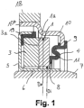
- Fig. 1 shows a mechanical seal, comprising a mechanical seal 1, which is mounted axially movably, and a counter ring 3, wherein the mechanical seal 1 and the counter ring 3 each have sealing surfaces 1a, 3a lying against one another, the sealing surface 1a of the mechanical ring 1 being the sealing surface 3a of the counter ring 3 is opposite and the sliding ring 1 is pressed against the counter ring 3 by a bellows-like spring means 4.
- Dm and s should be used in the same unit, for example in m.
- At least one sealing surface 1a, 3a has elevations or unevenness in the size of 0.1 ⁇ m to 500 ⁇ m.
- the counter ring 3 is received by a support body 5, which has an axial extension 6 for pressing onto a shaft 7.
- the elevations or bumps are designed as wave troughs and wave crests.
- the elevations or bumps on at least one sealing surface 1a, 3a can be at least partially deformed by the bellows-like spring means 4 in such a way that no functional impairment occurs during operation of the mechanical seal.
- the bellows-like spring means 4 rests on the slide ring 1 with an annular stop area 8 and is fixed to a housing 10 with an annular connection area 9, the stop area 8 and the connection area 9 being connected to one another by at least one elastically deformable hinge area 11.
- the hinge area 11 is S-shaped in cross section.
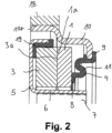
- Fig. 2 shows that the support body 5 with its axial extension 6 can be pressed onto the shaft 7.
- Fig. 3 shows that an area 6a of the extension 6 is designed in a truncated conical cross-section such that the interior of the extension 6 is conical to accommodate a shaft 7.
- the counter ring 3 is decoupled from forces that are introduced into the support body 5 by a press fit of the extension 6.
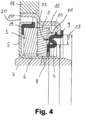
- Fig. 4 shows a mechanical seal in which a first annular surface 12 is formed on the sliding ring 1, on which a first force F1 can act in the axial direction, the first force F1 being directed in the direction of the counter ring 3.
- a projected, second annular surface 13 is provided.
- the projected, second annular surface 13 extends in the radial direction between a stop region 8 of the spring means 4 on the slide ring 1 and a connection region 9 of the spring means 4 on a housing 10.
- the second force F2 is between 1% and 100,000% of a first force F1, which acts on the first annular surface 12 axially in the direction of the counter ring 3.
- the first force F1 is advantageously greater than the second force F2.
- a pressure force acting on the sliding ring 1 can be compensated for by the spring means 4.
- the quotient of the first circular ring surface 12 on the slide ring 1, which faces the spring means 4, and the projected, second circular ring surface 13, which is between the stop area 8 of the spring means 4 on the slide ring 1 and the connection area 9 of the spring means 4 on the housing 10 extends, chosen in such a way that by changing the pressure in a space 20, the second force F2 acting axially in the direction of the sliding ring 1 on the projected, second annular surface 13 is between 1% and 100,000% of the first force F1, which is caused by changing the pressure in a space 20 acts on the first circular ring surface 12 axially in the direction of the counter ring 3.
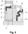
- Fig. 5 shows a mechanical seal in which the spring means 4a has a radial lip 14a resting on the sliding ring 1, which has a larger inner diameter than the support body 5 '.
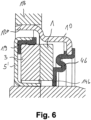
- Fig. 6 shows that the spring means 4b has a radial lip 14b resting on the sliding ring 1, which has the same inner diameter as the support body 5 '.
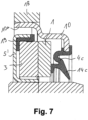
- Fig. 7 shows that the spring means 4c has a radial lip 14c, which protrudes from the slide ring 1 at an angle and has a larger inner diameter than the support body 5 '.
- Fig. 8 shows that the spring means 4d has a radial lip 14d, which protrudes from the slide ring 1 at an angle and has the same inner diameter as the support body 5 '.
- Fig. 9 shows that the spring means 4 has a dust lip 15a resting on its stop region 8, which has a larger inner diameter than the support body 5 '.
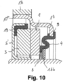
- Fig. 10 shows that the spring means 4 has a dust lip 15b resting on its stop area 8, which has the same inner diameter as the support body 5 '.
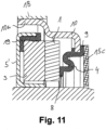
- Fig. 11 shows that the spring means 4 has a dust lip 15c resting on its connection area 9, which has a larger inner diameter than the support body 5 '.
- Fig. 12 shows that the spring means 4 has a dust lip 15d resting on its connection area 9, which has the same inner diameter as the support body 5 '.
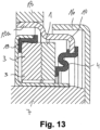
- Fig. 13 shows that the spring means 4 is at least partially surrounded by a wall 16 in the axial and/or radial direction. This results in a chambering of the spring means 4. A labyrinth seal is created.
- Fig. 14 shows that the wall 16a is part of a support body 5" in which the counter ring 3 is accommodated.
- Fig. 15 shows that a gap 17 is included between the extension 6'" and the counter ring 3.
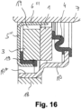
- Fig. 16 shows the lower part of the mechanical seal according to Fig. 15 .
- the gap 17 functions here as a collecting channel for oil, which can be returned.
- Fig. 17 shows that the extension 6 extends so far in the axial direction that the sliding ring 1 is also undercut by the extension 6.
- the counter ring 3 is designed and/or arranged in such a way that rotational forces induce slight conicity or deformation. This applies to everyone in the Fig. 1 to 18 mechanical seals described.
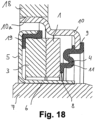
- Fig. 18 shows a mechanical seal in which an area 10a of the housing is applied to a counter wall 18 in a metal sealing manner, fully rubberized, partially rubberized or with the interposition of a sealing compound, in particular a sealing varnish.
- the counter ring 3 could be designed symmetrically so that centrifugal forces have no influence on its deformation.
- the extension 6 could be statically sealed relative to the shaft 7.
- the static seal can be fully rubberized, partially rubberized, with sealing varnish or have a metallic seal.
- a signal track 19 is assigned to the counter ring 3. This allows the mechanical seal to also function as an encoder.
- the signal track 19 can consist of an elastomer in which magnetizable or magnetized particles are accommodated.
- Fig. 19 shows the waviness of the sliding ring 1 as it rotates on its sealing surface 1a.
- the angle ⁇ takes values between 0 and 360 degrees.
- Fig. 19 It is shown that two high points and two low points are passed through when one runs around a sealing surface 1a.
- the elevations or bumps on a sealing surface 1a therefore have two high points and two low points, namely two wave crests and two wave troughs.
- the elevations or bumps on a sealing surface 1a, 3a can be at least partially deformed by the bellows-like spring means 4 in such a way that no impairment of the function of the mechanical seal occurs during operation.
Landscapes
- Engineering & Computer Science (AREA)
- General Engineering & Computer Science (AREA)
- Mechanical Engineering (AREA)
- Mechanical Sealing (AREA)
Claims (18)
- Joint d'étanchéité à bague de glissement comprenant une bague de glissement (1) qui est supporté de manière déplaçable axialement, et une bague conjuguée (3), la bague de glissement (1) et la bague conjuguée (3) présentant chacune des surfaces d'étanchéité en appui l'une contre l'autre (1a, 3a), la surface d'étanchéité (1a) de la bague de glissement (1) étant en regard de la surface d'étanchéité (3a) de la bague conjuguée (3) et la bague de glissement (1) étant pressée contre la bague conjuguée (3) par un moyen de ressort de type soufflet (4), la bague conjuguée (3) étant reçue par un corps de support (5) qui présente une saillie axiale (6) destinée à presser contre un arbre (7), caractérisé en ce qu'au moins une surface d'étanchéité (1a, 3a) présente des rehaussements ou des inégalités d'un ordre de grandeur de 0,1 µm à W mm, W se calculant d'après la formule

- Joint d'étanchéité à bague de glissement selon la revendication 1, caractérisé en ce qu'au moins une surface d'étanchéité (1a, 3a) présente des rehaussements ou des inégalités d'un ordre de grandeur entre 1 µm et W, de préférence d'un ordre de grandeur entre 5 µm et W, en particulier préférablement d'un ordre de grandeur entre 20 µm et W, au maximum de préférence d'un ordre de grandeur entre 50 µm et W.
- Joint d'étanchéité à bague de glissement selon la revendication 1 ou 2, caractérisé en ce que les rehaussements ou les inégalités sont configurés sous forme de creux d'ondulations et de pics d'ondulations.
- Joint d'étanchéité à bague de glissement selon l'une quelconque des revendications précédentes, caractérisé en ce que les rehaussements ou les inégalités sur une surface d'étanchéité (1a, 3a) présentent au moins deux points supérieurs et deux points inférieurs, de préférence trois points supérieurs et trois points inférieurs, en particulier préférablement quatre points supérieurs et quatre points inférieurs.
- Joint d'étanchéité à bague de glissement selon l'une quelconque des revendications précédentes, caractérisé en ce que les rehaussements ou les inégalités sur au moins une surface d'étanchéité (1a, 3a) peuvent être déformés au moins en partie par le moyen de ressort de type soufflet (4) de telle sorte que pendant le fonctionnement du joint d'étanchéité à bague de glissement, aucun effet adverse sur le fonctionnement ne se produise.
- Joint d'étanchéité à bague de glissement selon l'une quelconque des revendications précédentes, caractérisé en ce que le moyen de ressort de type soufflet (4) s'applique avec une région de butée de forme annulaire (8) contre la bague de glissement (1) et est fixé avec une région de liaison de forme annulaire (9) contre un boîtier (9), la région de butée (8) et la région de liaison (9) étant raccordées l'une à l'autre par au moins une région de charnière élastiquement déformable (11).
- Joint d'étanchéité à bague de glissement selon l'une quelconque des revendications précédente, caractérisé en ce que le quotient d'une première surface annulaire circulaire (12) au niveau de la bague de glissement (1), qui est tournée vers le moyen de ressort (4), et d'une deuxième surface annulaire circulaire projetée (13), qui s'étend entre une région de butée (8) du moyen de ressort (4) au niveau de la bague de glissement (1) et une région de liaison (9) du moyen de ressort (4) au niveau d'un boîtier (10), est choisi de telle sorte qu'une deuxième force agissant axialement dans la direction de la bague de glissement (1) sur la deuxième surface annulaire circulaire projetée (13) aille entre 1 % et 100000 %, de préférence entre 10 % et 1000 %, en particulier préférablement entre 10 % et 100 %, d'une première force qui agit sur la première surface annulaire circulaire (12) axialement dans la direction de la bague conjuguée (3).
- Joint d'étanchéité à bague de glissement selon l'une quelconque des revendications 1 ou 7, caractérisé en ce que le moyen de ressort (4a) présente une lèvre radiale (14a) s'appliquant contre la bague de glissement (1), laquelle présente un diamètre intérieur supérieur ou égal à celui du corps de support (5').
- Joint d'étanchéité à bague de glissement selon l'une quelconque des revendications 1 ou 7, caractérisé en ce que le moyen de ressort (4c) présente une lèvre radiale (14c) qui dépasse de la bague de glissement (1) en formant un angle et qui présente un diamètre intérieur supérieur ou égal à celui du corps de support (5').
- Joint d'étanchéité à bague de glissement selon l'une quelconque des revendications 1 ou 7, caractérisé en ce que le moyen de ressort (4) présente une lèvre antipoussière (15a) s'appliquant contre sa région de butée (8), laquelle présente un diamètre intérieur supérieur ou égal à celui du corps de support (5').
- Joint d'étanchéité à bague de glissement selon l'une quelconque des revendications 1 ou 7, caractérisé en ce que le moyen de ressort (4) présente une lèvre antipoussière (15c) s'appliquant contre sa région de liaison (9), laquelle présente un diamètre intérieur supérieur ou égal à celui du corps de support (5').
- Joint d'étanchéité à bague de glissement selon l'une quelconque des revendications précédentes, caractérisé en ce que le moyen de ressort (4) est entouré au moins en partie dans la direction axiale et/ou radiale par une paroi (16).
- Joint d'étanchéité à bague de glissement selon la revendication 12, caractérisé en ce que la paroi (16a) est une partie d'un corps de support (5"), dans lequel est reçue la bague conjuguée (3).
- Joint d'étanchéité à bague de glissement selon l'une quelconque des revendications 1 ou 7 à 13, caractérisé en ce qu'entre la saillie (6‴) et la bague conjuguée (3) est réalisée une fente (17).
- Joint d'étanchéité à bague de glissement selon l'une quelconque des revendications 1 ou 7 à 14, caractérisé en ce que la saillie (6) s'étend dans la direction axiale sur une longueur telle que la saillie (6) s'étend également en dessous de la bague de glissement (1).
- Joint d'étanchéité à bague de glissement selon l'une quelconque des revendications précédentes, caractérisé par une lubrification à gaz.
- Joint d'étanchéité à bague de glissement selon l'une quelconque des revendications précédentes, caractérisé en ce que la surface d'étanchéité (1a) de la bague de glissement (1) et/ou la surface d'étanchéité (3a) de la bague conjuguée (3) présentent des structures hydrodynamiques.
- Utilisation d'un joint d'étanchéité à bague de glissement selon l'une quelconque des revendications précédentes, en tant que garniture d'étanchéité du vilebrequin de moteurs à combustion interne.
Priority Applications (1)
| Application Number | Priority Date | Filing Date | Title |
|---|---|---|---|
| EP14720469.7A EP2861897B2 (fr) | 2013-04-22 | 2014-04-08 | Joint d'étanchéité à bague de glissement |
Applications Claiming Priority (4)
| Application Number | Priority Date | Filing Date | Title |
|---|---|---|---|
| DE102013006840 | 2013-04-22 | ||
| PCT/EP2013/002050 WO2014173425A1 (fr) | 2013-04-22 | 2013-07-11 | Joint d'étanchéité à bague coulissante |
| EP14720469.7A EP2861897B2 (fr) | 2013-04-22 | 2014-04-08 | Joint d'étanchéité à bague de glissement |
| PCT/EP2014/000936 WO2014173495A2 (fr) | 2013-04-22 | 2014-04-08 | Joint d'étanchéité à bague de glissement |
Publications (3)
| Publication Number | Publication Date |
|---|---|
| EP2861897A2 EP2861897A2 (fr) | 2015-04-22 |
| EP2861897B1 EP2861897B1 (fr) | 2016-09-21 |
| EP2861897B2 true EP2861897B2 (fr) | 2023-12-06 |
Family
ID=50628750
Family Applications (1)
| Application Number | Title | Priority Date | Filing Date |
|---|---|---|---|
| EP14720469.7A Active EP2861897B2 (fr) | 2013-04-22 | 2014-04-08 | Joint d'étanchéité à bague de glissement |
Country Status (2)
| Country | Link |
|---|---|
| EP (1) | EP2861897B2 (fr) |
| WO (1) | WO2014173495A2 (fr) |
Families Citing this family (1)
| Publication number | Priority date | Publication date | Assignee | Title |
|---|---|---|---|---|
| FR3070724B1 (fr) * | 2017-09-07 | 2022-05-27 | Renault Sas | Moteur comportant un deflecteur pour bague d'etancheite pour un vilebrequin de vehicule automobile |
Citations (4)
| Publication number | Priority date | Publication date | Assignee | Title |
|---|---|---|---|---|
| DE4419538A1 (de) † | 1994-06-03 | 1995-12-07 | Merkel Martin Gmbh Co Kg | Gleitringdichtung |
| EP1164302B1 (fr) † | 2000-06-16 | 2006-07-05 | Grundfos A/S | Palier axial à glissement pour une pompe centrifuge à rotor mouillé |
| DE102006028153B4 (de) † | 2006-06-16 | 2008-06-05 | Flowserve Dortmund Gmbh & Co. Kg | Gleitringdichtung für eine rotierende Welle |
| EP2306052A1 (fr) † | 2009-10-01 | 2011-04-06 | KACO GmbH + Co. KG | Joint mécanique |
Family Cites Families (3)
| Publication number | Priority date | Publication date | Assignee | Title |
|---|---|---|---|---|
| GB2061411A (en) * | 1979-10-19 | 1981-05-13 | Rubber & Plastic Res Ass | Stern shaft seal |
| DE10315333B4 (de) * | 2003-04-03 | 2005-10-27 | Carl Freudenberg Kg | Dichtung |
| DE102011114349A1 (de) * | 2010-09-30 | 2012-04-05 | Carl Freudenberg Kg | Gleitringdichtung |
-
2014
- 2014-04-08 EP EP14720469.7A patent/EP2861897B2/fr active Active
- 2014-04-08 WO PCT/EP2014/000936 patent/WO2014173495A2/fr not_active Ceased
Patent Citations (4)
| Publication number | Priority date | Publication date | Assignee | Title |
|---|---|---|---|---|
| DE4419538A1 (de) † | 1994-06-03 | 1995-12-07 | Merkel Martin Gmbh Co Kg | Gleitringdichtung |
| EP1164302B1 (fr) † | 2000-06-16 | 2006-07-05 | Grundfos A/S | Palier axial à glissement pour une pompe centrifuge à rotor mouillé |
| DE102006028153B4 (de) † | 2006-06-16 | 2008-06-05 | Flowserve Dortmund Gmbh & Co. Kg | Gleitringdichtung für eine rotierende Welle |
| EP2306052A1 (fr) † | 2009-10-01 | 2011-04-06 | KACO GmbH + Co. KG | Joint mécanique |
Non-Patent Citations (11)
| Title |
|---|
| A test Apparatus for Measuring the Effects of Waviness in Mechanical Face Seals, A O.Lebeck. ASLE transactions. 1981 Vol. 24, S 371-378 † |
| A.O. LEBECK: "Mechanical Loading - A Primary Source of Waviness in Mechanical Face Seals", ASLE TRANSACTIONS, vol. 20, no. 1, 1977, pages 195 - 208 † |
| ABD der Gleitringdichtung, Feodor Burgmann, 1988, S. 175 † |
| Development of a non contacting seal for gas/liquid applications using wavy face technology", Lionle A Young, William E. (Bill) Key, Ronald L. (Ron) Grace, "13th International Pump Users Symposium", Houston, USA, Mar 5-7, 1996, S 39-45 † |
| Dichtungsringe fur dynamische Dichtungen, Schunk Kohlenstofftechnik GmbH, 2009 † |
| Gleitringdichtungen fur Pumpen, Grundfos Management A/S, 2009, S. 68 † |
| Handbuch der Dichtungstechnik, Edgar Schmid, Expert Verlag, 1981, S 404 † |
| Investigation of Surface Waves on Hydrodynamic Lubrification, George Costa, B.S Mechanical Engineering, University of Massachusetts Datmouth, 1998, Juni 2000, S 1-9 und 26 † |
| Mechanical Face Seal Handbook, John C Dahlheimer, 1972, S 26 † |
| Mechanical Face Seal Handbook, John C Dahlheimer, 1972, S. 8 † |
| VON A.O. LEBECK: "Face Seal Waviness Prediction, Measurement, Causes and Effects", 10TH INTERNATIONAL CONFERENCE ON FLUID SEALING, 1984, pages 295 - 312 † |
Also Published As
| Publication number | Publication date |
|---|---|
| WO2014173495A2 (fr) | 2014-10-30 |
| EP2861897B1 (fr) | 2016-09-21 |
| WO2014173495A3 (fr) | 2015-03-12 |
| EP2861897A2 (fr) | 2015-04-22 |
Similar Documents
| Publication | Publication Date | Title |
|---|---|---|
| EP1299662B1 (fr) | Bague d'etancheite | |
| EP3030793B1 (fr) | Unité de raclage et dispositif de travail hydraulique comportant une unité de raclage | |
| DE102011114349A1 (de) | Gleitringdichtung | |
| EP2988035A1 (fr) | Joint d'etancheite et son utilisation | |
| DE102016208697A1 (de) | Rotationsdichtungsanordnung mit druckaktivierbarer Rotationsdichtung sowie Rotationsdichtung | |
| EP2561255B1 (fr) | Bague collectrice d'étanchéité | |
| DE102018122000A1 (de) | Wellendichtung mit einem Wellendichtring | |
| EP3872373B1 (fr) | Bague d'étanchéité et son utilisation | |
| EP2861897B2 (fr) | Joint d'étanchéité à bague de glissement | |
| DE102014007968A1 (de) | Anordnung mit einem Radialwellendichtring mit sinusförmig geschwungener Dichtkante | |
| DE19914929C2 (de) | Gleitringdichtung | |
| EP4515126A1 (fr) | Bague d'étanchéité d'arbre radiale, joint d'étanchéité d'arbre radial et agencement de joint d'étanchéité d'arbre radial | |
| WO2015067364A1 (fr) | Ensemble à racleur et/ou ensemble à bague d'étanchéité et racleur et/ou bague d'étanchéité destinés à un tel ensemble | |
| EP1998089B1 (fr) | Agencement de joint, bague d'étanchéité et leur utilisation | |
| EP4226061B1 (fr) | Agencement d'étanchéité pour roulements de roue et ensemble roulement de roue doté d'agencement d'étanchéité | |
| DE102010024284B4 (de) | Gleitringdichtung mit stationärem Gleitring mit Ausnehmungen | |
| EP4001708B1 (fr) | Bague d'étanchéité et son utilisation | |
| DE102010012844B4 (de) | Dichtung mit Laufhülse mit Schmiertaschen | |
| EP4239229B1 (fr) | Bague d'étanchéité axiale | |
| EP3502524A1 (fr) | Joint d'étanchéité à anneau glissant ainsi que groupe turbogénérateur doté d'un tel joint d'étanchéité à anneau glissant | |
| DE10238166B4 (de) | Gleitringdichtung | |
| EP1388694B1 (fr) | Dispositif d'étanchéité | |
| DE102017004480A1 (de) | Dichtring und Dichtungsanordnung, die den Dichtring umfasst | |
| DE202016102691U1 (de) | Rotationsdichtungsanordnung mit druckaktivierbarer Rotationsdichtung sowie Rotationsdichtung | |
| DE102004061384B3 (de) | Wälzlagerabdichtung |
Legal Events
| Date | Code | Title | Description |
|---|---|---|---|
| PUAI | Public reference made under article 153(3) epc to a published international application that has entered the european phase |
Free format text: ORIGINAL CODE: 0009012 |
|
| 17P | Request for examination filed |
Effective date: 20140425 |
|
| AK | Designated contracting states |
Kind code of ref document: A2 Designated state(s): AL AT BE BG CH CY CZ DE DK EE ES FI FR GB GR HR HU IE IS IT LI LT LU LV MC MK MT NL NO PL PT RO RS SE SI SK SM TR |
|
| AX | Request for extension of the european patent |
Extension state: BA ME |
|
| GRAP | Despatch of communication of intention to grant a patent |
Free format text: ORIGINAL CODE: EPIDOSNIGR1 |
|
| DAX | Request for extension of the european patent (deleted) | ||
| INTG | Intention to grant announced |
Effective date: 20160329 |
|
| GRAS | Grant fee paid |
Free format text: ORIGINAL CODE: EPIDOSNIGR3 |
|
| GRAA | (expected) grant |
Free format text: ORIGINAL CODE: 0009210 |
|
| AK | Designated contracting states |
Kind code of ref document: B1 Designated state(s): AL AT BE BG CH CY CZ DE DK EE ES FI FR GB GR HR HU IE IS IT LI LT LU LV MC MK MT NL NO PL PT RO RS SE SI SK SM TR |
|
| REG | Reference to a national code |
Ref country code: GB Ref legal event code: FG4D Free format text: NOT ENGLISH |
|
| REG | Reference to a national code |
Ref country code: CH Ref legal event code: EP |
|
| REG | Reference to a national code |
Ref country code: AT Ref legal event code: REF Ref document number: 831334 Country of ref document: AT Kind code of ref document: T Effective date: 20161015 |
|
| REG | Reference to a national code |
Ref country code: IE Ref legal event code: FG4D Free format text: LANGUAGE OF EP DOCUMENT: GERMAN |
|
| REG | Reference to a national code |
Ref country code: DE Ref legal event code: R096 Ref document number: 502014001536 Country of ref document: DE |
|
| REG | Reference to a national code |
Ref country code: LT Ref legal event code: MG4D Ref country code: NL Ref legal event code: MP Effective date: 20160921 |
|
| PG25 | Lapsed in a contracting state [announced via postgrant information from national office to epo] |
Ref country code: LT Free format text: LAPSE BECAUSE OF FAILURE TO SUBMIT A TRANSLATION OF THE DESCRIPTION OR TO PAY THE FEE WITHIN THE PRESCRIBED TIME-LIMIT Effective date: 20160921 Ref country code: FI Free format text: LAPSE BECAUSE OF FAILURE TO SUBMIT A TRANSLATION OF THE DESCRIPTION OR TO PAY THE FEE WITHIN THE PRESCRIBED TIME-LIMIT Effective date: 20160921 Ref country code: RS Free format text: LAPSE BECAUSE OF FAILURE TO SUBMIT A TRANSLATION OF THE DESCRIPTION OR TO PAY THE FEE WITHIN THE PRESCRIBED TIME-LIMIT Effective date: 20160921 Ref country code: NO Free format text: LAPSE BECAUSE OF FAILURE TO SUBMIT A TRANSLATION OF THE DESCRIPTION OR TO PAY THE FEE WITHIN THE PRESCRIBED TIME-LIMIT Effective date: 20161221 |
|
| PG25 | Lapsed in a contracting state [announced via postgrant information from national office to epo] |
Ref country code: NL Free format text: LAPSE BECAUSE OF FAILURE TO SUBMIT A TRANSLATION OF THE DESCRIPTION OR TO PAY THE FEE WITHIN THE PRESCRIBED TIME-LIMIT Effective date: 20160921 Ref country code: LV Free format text: LAPSE BECAUSE OF FAILURE TO SUBMIT A TRANSLATION OF THE DESCRIPTION OR TO PAY THE FEE WITHIN THE PRESCRIBED TIME-LIMIT Effective date: 20160921 Ref country code: SE Free format text: LAPSE BECAUSE OF FAILURE TO SUBMIT A TRANSLATION OF THE DESCRIPTION OR TO PAY THE FEE WITHIN THE PRESCRIBED TIME-LIMIT Effective date: 20160921 Ref country code: GR Free format text: LAPSE BECAUSE OF FAILURE TO SUBMIT A TRANSLATION OF THE DESCRIPTION OR TO PAY THE FEE WITHIN THE PRESCRIBED TIME-LIMIT Effective date: 20161222 |
|
| PG25 | Lapsed in a contracting state [announced via postgrant information from national office to epo] |
Ref country code: RO Free format text: LAPSE BECAUSE OF FAILURE TO SUBMIT A TRANSLATION OF THE DESCRIPTION OR TO PAY THE FEE WITHIN THE PRESCRIBED TIME-LIMIT Effective date: 20160921 Ref country code: EE Free format text: LAPSE BECAUSE OF FAILURE TO SUBMIT A TRANSLATION OF THE DESCRIPTION OR TO PAY THE FEE WITHIN THE PRESCRIBED TIME-LIMIT Effective date: 20160921 |
|
| REG | Reference to a national code |
Ref country code: HU Ref legal event code: AG4A Ref document number: E029957 Country of ref document: HU |
|
| REG | Reference to a national code |
Ref country code: FR Ref legal event code: PLFP Year of fee payment: 4 |
|
| PG25 | Lapsed in a contracting state [announced via postgrant information from national office to epo] |
Ref country code: SM Free format text: LAPSE BECAUSE OF FAILURE TO SUBMIT A TRANSLATION OF THE DESCRIPTION OR TO PAY THE FEE WITHIN THE PRESCRIBED TIME-LIMIT Effective date: 20160921 Ref country code: BG Free format text: LAPSE BECAUSE OF FAILURE TO SUBMIT A TRANSLATION OF THE DESCRIPTION OR TO PAY THE FEE WITHIN THE PRESCRIBED TIME-LIMIT Effective date: 20161221 Ref country code: IS Free format text: LAPSE BECAUSE OF FAILURE TO SUBMIT A TRANSLATION OF THE DESCRIPTION OR TO PAY THE FEE WITHIN THE PRESCRIBED TIME-LIMIT Effective date: 20170121 Ref country code: PT Free format text: LAPSE BECAUSE OF FAILURE TO SUBMIT A TRANSLATION OF THE DESCRIPTION OR TO PAY THE FEE WITHIN THE PRESCRIBED TIME-LIMIT Effective date: 20170123 |
|
| REG | Reference to a national code |
Ref country code: SK Ref legal event code: T3 Ref document number: E 22910 Country of ref document: SK |
|
| REG | Reference to a national code |
Ref country code: DE Ref legal event code: R026 Ref document number: 502014001536 Country of ref document: DE |
|
| PLBI | Opposition filed |
Free format text: ORIGINAL CODE: 0009260 |
|
| PLAX | Notice of opposition and request to file observation + time limit sent |
Free format text: ORIGINAL CODE: EPIDOSNOBS2 |
|
| PG25 | Lapsed in a contracting state [announced via postgrant information from national office to epo] |
Ref country code: DK Free format text: LAPSE BECAUSE OF FAILURE TO SUBMIT A TRANSLATION OF THE DESCRIPTION OR TO PAY THE FEE WITHIN THE PRESCRIBED TIME-LIMIT Effective date: 20160921 |
|
| 26 | Opposition filed |
Opponent name: KACO GMBH & CO. KG Effective date: 20170621 |
|
| RIN2 | Information on inventor provided after grant (corrected) |
Inventor name: BOCK, EBERHARD, DR. Inventor name: LANG, KLAUS, DR. Inventor name: NEUBERGER, SOEREN Inventor name: GUENTERT, ALEXANDER |
|
| REG | Reference to a national code |
Ref country code: HU Ref legal event code: HC9C |
|
| REG | Reference to a national code |
Ref country code: SK Ref legal event code: TC4A Ref document number: E 22910 Country of ref document: SK Owner name: GUENTERT ALEXANDER, HEIDELBERG, DE Effective date: 20171017 Ref country code: SK Ref legal event code: TC4A Ref document number: E 22910 Country of ref document: SK Owner name: BOCK EBERHARD DR., MOERLENBACH, DE Effective date: 20171017 Ref country code: SK Ref legal event code: TC4A Ref document number: E 22910 Country of ref document: SK Owner name: NEUBERGER SOEREN, HOCKENHEIM, DE Effective date: 20171017 Ref country code: SK Ref legal event code: TC4A Ref document number: E 22910 Country of ref document: SK Owner name: LANG KLAUS DR., EURASBURG, DE Effective date: 20171017 |
|
| PG25 | Lapsed in a contracting state [announced via postgrant information from national office to epo] |
Ref country code: SI Free format text: LAPSE BECAUSE OF FAILURE TO SUBMIT A TRANSLATION OF THE DESCRIPTION OR TO PAY THE FEE WITHIN THE PRESCRIBED TIME-LIMIT Effective date: 20160921 |
|
| REG | Reference to a national code |
Ref country code: CH Ref legal event code: PL |
|
| PLBB | Reply of patent proprietor to notice(s) of opposition received |
Free format text: ORIGINAL CODE: EPIDOSNOBS3 |
|
| REG | Reference to a national code |
Ref country code: IE Ref legal event code: MM4A |
|
| PG25 | Lapsed in a contracting state [announced via postgrant information from national office to epo] |
Ref country code: MC Free format text: LAPSE BECAUSE OF FAILURE TO SUBMIT A TRANSLATION OF THE DESCRIPTION OR TO PAY THE FEE WITHIN THE PRESCRIBED TIME-LIMIT Effective date: 20160921 |
|
| PG25 | Lapsed in a contracting state [announced via postgrant information from national office to epo] |
Ref country code: LU Free format text: LAPSE BECAUSE OF NON-PAYMENT OF DUE FEES Effective date: 20170408 Ref country code: LI Free format text: LAPSE BECAUSE OF NON-PAYMENT OF DUE FEES Effective date: 20170430 Ref country code: CH Free format text: LAPSE BECAUSE OF NON-PAYMENT OF DUE FEES Effective date: 20170430 |
|
| REG | Reference to a national code |
Ref country code: BE Ref legal event code: MM Effective date: 20170430 |
|
| REG | Reference to a national code |
Ref country code: FR Ref legal event code: PLFP Year of fee payment: 5 |
|
| PG25 | Lapsed in a contracting state [announced via postgrant information from national office to epo] |
Ref country code: IE Free format text: LAPSE BECAUSE OF NON-PAYMENT OF DUE FEES Effective date: 20170408 |
|
| RIN2 | Information on inventor provided after grant (corrected) |
Inventor name: GUENTERT, ALEXANDER Inventor name: NEUBERGER, SOEREN Inventor name: BOCK, EBERHARD, DR. Inventor name: LANG, KLAUS, DR. |
|
| PG25 | Lapsed in a contracting state [announced via postgrant information from national office to epo] |
Ref country code: BE Free format text: LAPSE BECAUSE OF NON-PAYMENT OF DUE FEES Effective date: 20170430 |
|
| PG25 | Lapsed in a contracting state [announced via postgrant information from national office to epo] |
Ref country code: MT Free format text: LAPSE BECAUSE OF FAILURE TO SUBMIT A TRANSLATION OF THE DESCRIPTION OR TO PAY THE FEE WITHIN THE PRESCRIBED TIME-LIMIT Effective date: 20160921 |
|
| PG25 | Lapsed in a contracting state [announced via postgrant information from national office to epo] |
Ref country code: AL Free format text: LAPSE BECAUSE OF FAILURE TO SUBMIT A TRANSLATION OF THE DESCRIPTION OR TO PAY THE FEE WITHIN THE PRESCRIBED TIME-LIMIT Effective date: 20160921 |
|
| APBM | Appeal reference recorded |
Free format text: ORIGINAL CODE: EPIDOSNREFNO |
|
| APBP | Date of receipt of notice of appeal recorded |
Free format text: ORIGINAL CODE: EPIDOSNNOA2O |
|
| APAH | Appeal reference modified |
Free format text: ORIGINAL CODE: EPIDOSCREFNO |
|
| APBM | Appeal reference recorded |
Free format text: ORIGINAL CODE: EPIDOSNREFNO |
|
| APBP | Date of receipt of notice of appeal recorded |
Free format text: ORIGINAL CODE: EPIDOSNNOA2O |
|
| APBQ | Date of receipt of statement of grounds of appeal recorded |
Free format text: ORIGINAL CODE: EPIDOSNNOA3O |
|
| APBQ | Date of receipt of statement of grounds of appeal recorded |
Free format text: ORIGINAL CODE: EPIDOSNNOA3O |
|
| PG25 | Lapsed in a contracting state [announced via postgrant information from national office to epo] |
Ref country code: CY Free format text: LAPSE BECAUSE OF FAILURE TO SUBMIT A TRANSLATION OF THE DESCRIPTION OR TO PAY THE FEE WITHIN THE PRESCRIBED TIME-LIMIT Effective date: 20160921 |
|
| PG25 | Lapsed in a contracting state [announced via postgrant information from national office to epo] |
Ref country code: MK Free format text: LAPSE BECAUSE OF FAILURE TO SUBMIT A TRANSLATION OF THE DESCRIPTION OR TO PAY THE FEE WITHIN THE PRESCRIBED TIME-LIMIT Effective date: 20160921 |
|
| PG25 | Lapsed in a contracting state [announced via postgrant information from national office to epo] |
Ref country code: TR Free format text: LAPSE BECAUSE OF FAILURE TO SUBMIT A TRANSLATION OF THE DESCRIPTION OR TO PAY THE FEE WITHIN THE PRESCRIBED TIME-LIMIT Effective date: 20160921 |
|
| PGFP | Annual fee paid to national office [announced via postgrant information from national office to epo] |
Ref country code: PL Payment date: 20200324 Year of fee payment: 7 |
|
| PGFP | Annual fee paid to national office [announced via postgrant information from national office to epo] |
Ref country code: CZ Payment date: 20200324 Year of fee payment: 7 Ref country code: SK Payment date: 20200323 Year of fee payment: 7 |
|
| PG25 | Lapsed in a contracting state [announced via postgrant information from national office to epo] |
Ref country code: HR Free format text: LAPSE BECAUSE OF FAILURE TO SUBMIT A TRANSLATION OF THE DESCRIPTION OR TO PAY THE FEE WITHIN THE PRESCRIBED TIME-LIMIT Effective date: 20160921 |
|
| PGFP | Annual fee paid to national office [announced via postgrant information from national office to epo] |
Ref country code: ES Payment date: 20200505 Year of fee payment: 7 |
|
| REG | Reference to a national code |
Ref country code: AT Ref legal event code: MM01 Ref document number: 831334 Country of ref document: AT Kind code of ref document: T Effective date: 20190408 |
|
| PGFP | Annual fee paid to national office [announced via postgrant information from national office to epo] |
Ref country code: GB Payment date: 20200424 Year of fee payment: 7 Ref country code: HU Payment date: 20200407 Year of fee payment: 7 |
|
| PG25 | Lapsed in a contracting state [announced via postgrant information from national office to epo] |
Ref country code: AT Free format text: LAPSE BECAUSE OF NON-PAYMENT OF DUE FEES Effective date: 20190408 |
|
| REG | Reference to a national code |
Ref country code: SK Ref legal event code: MM4A Ref document number: E 22910 Country of ref document: SK Effective date: 20210408 |
|
| GBPC | Gb: european patent ceased through non-payment of renewal fee |
Effective date: 20210408 |
|
| PG25 | Lapsed in a contracting state [announced via postgrant information from national office to epo] |
Ref country code: CZ Free format text: LAPSE BECAUSE OF NON-PAYMENT OF DUE FEES Effective date: 20210408 Ref country code: SK Free format text: LAPSE BECAUSE OF NON-PAYMENT OF DUE FEES Effective date: 20210408 Ref country code: GB Free format text: LAPSE BECAUSE OF NON-PAYMENT OF DUE FEES Effective date: 20210408 Ref country code: HU Free format text: LAPSE BECAUSE OF NON-PAYMENT OF DUE FEES Effective date: 20210409 |
|
| REG | Reference to a national code |
Ref country code: ES Ref legal event code: FD2A Effective date: 20220701 |
|
| PG25 | Lapsed in a contracting state [announced via postgrant information from national office to epo] |
Ref country code: ES Free format text: LAPSE BECAUSE OF NON-PAYMENT OF DUE FEES Effective date: 20210409 |
|
| PG25 | Lapsed in a contracting state [announced via postgrant information from national office to epo] |
Ref country code: PL Free format text: LAPSE BECAUSE OF NON-PAYMENT OF DUE FEES Effective date: 20210408 |
|
| APBU | Appeal procedure closed |
Free format text: ORIGINAL CODE: EPIDOSNNOA9O |
|
| PUAH | Patent maintained in amended form |
Free format text: ORIGINAL CODE: 0009272 |
|
| STAA | Information on the status of an ep patent application or granted ep patent |
Free format text: STATUS: PATENT MAINTAINED AS AMENDED |
|
| 27A | Patent maintained in amended form |
Effective date: 20231206 |
|
| AK | Designated contracting states |
Kind code of ref document: B2 Designated state(s): AL AT BE BG CH CY CZ DE DK EE ES FI FR GB GR HR HU IE IS IT LI LT LU LV MC MK MT NL NO PL PT RO RS SE SI SK SM TR |
|
| REG | Reference to a national code |
Ref country code: DE Ref legal event code: R102 Ref document number: 502014001536 Country of ref document: DE |
|
| PGFP | Annual fee paid to national office [announced via postgrant information from national office to epo] |
Ref country code: DE Payment date: 20250428 Year of fee payment: 12 |
|
| PGFP | Annual fee paid to national office [announced via postgrant information from national office to epo] |
Ref country code: IT Payment date: 20250422 Year of fee payment: 12 |
|
| PGFP | Annual fee paid to national office [announced via postgrant information from national office to epo] |
Ref country code: FR Payment date: 20250424 Year of fee payment: 12 |