EP1388720A2 - Echangeur de chaleur à triple tubes et sa méthode de fabrication - Google Patents
Echangeur de chaleur à triple tubes et sa méthode de fabrication Download PDFInfo
- Publication number
- EP1388720A2 EP1388720A2 EP03018139A EP03018139A EP1388720A2 EP 1388720 A2 EP1388720 A2 EP 1388720A2 EP 03018139 A EP03018139 A EP 03018139A EP 03018139 A EP03018139 A EP 03018139A EP 1388720 A2 EP1388720 A2 EP 1388720A2
- Authority
- EP
- European Patent Office
- Prior art keywords
- tube
- end portions
- portions
- radially
- heat exchanger
- Prior art date
- Legal status (The legal status is an assumption and is not a legal conclusion. Google has not performed a legal analysis and makes no representation as to the accuracy of the status listed.)
- Granted
Links
- 238000000034 method Methods 0.000 title claims description 11
- 230000000994 depressogenic effect Effects 0.000 claims abstract description 44
- 230000002093 peripheral effect Effects 0.000 claims abstract description 18
- 238000005219 brazing Methods 0.000 claims description 30
- 239000007789 gas Substances 0.000 claims description 27
- 239000011324 bead Substances 0.000 claims description 8
- 230000001737 promoting effect Effects 0.000 claims description 6
- XLYOFNOQVPJJNP-UHFFFAOYSA-N water Substances O XLYOFNOQVPJJNP-UHFFFAOYSA-N 0.000 claims description 5
- 239000012530 fluid Substances 0.000 claims description 3
- 239000000112 cooling gas Substances 0.000 claims description 2
- 239000000498 cooling water Substances 0.000 description 11
- 230000004048 modification Effects 0.000 description 10
- 238000012986 modification Methods 0.000 description 10
- 239000000945 filler Substances 0.000 description 9
- 239000002184 metal Substances 0.000 description 9
- 229910052751 metal Inorganic materials 0.000 description 9
- 238000002485 combustion reaction Methods 0.000 description 6
- MWUXSHHQAYIFBG-UHFFFAOYSA-N nitrogen oxide Inorganic materials O=[N] MWUXSHHQAYIFBG-UHFFFAOYSA-N 0.000 description 5
- 239000007769 metal material Substances 0.000 description 4
- 238000010276 construction Methods 0.000 description 3
- 150000002739 metals Chemical class 0.000 description 3
- 229910001220 stainless steel Inorganic materials 0.000 description 3
- 239000010935 stainless steel Substances 0.000 description 3
- PXHVJJICTQNCMI-UHFFFAOYSA-N Nickel Chemical compound [Ni] PXHVJJICTQNCMI-UHFFFAOYSA-N 0.000 description 2
- 230000000694 effects Effects 0.000 description 2
- 238000004519 manufacturing process Methods 0.000 description 2
- 238000005352 clarification Methods 0.000 description 1
- 238000001816 cooling Methods 0.000 description 1
- 239000012809 cooling fluid Substances 0.000 description 1
- 230000007775 late Effects 0.000 description 1
- 239000000463 material Substances 0.000 description 1
- 229910052759 nickel Inorganic materials 0.000 description 1
- 239000002245 particle Substances 0.000 description 1
- 238000007789 sealing Methods 0.000 description 1
Images


Classifications
-
- F—MECHANICAL ENGINEERING; LIGHTING; HEATING; WEAPONS; BLASTING
- F28—HEAT EXCHANGE IN GENERAL
- F28D—HEAT-EXCHANGE APPARATUS, NOT PROVIDED FOR IN ANOTHER SUBCLASS, IN WHICH THE HEAT-EXCHANGE MEDIA DO NOT COME INTO DIRECT CONTACT
- F28D7/00—Heat-exchange apparatus having stationary tubular conduit assemblies for both heat-exchange media, the media being in contact with different sides of a conduit wall
- F28D7/10—Heat-exchange apparatus having stationary tubular conduit assemblies for both heat-exchange media, the media being in contact with different sides of a conduit wall the conduits being arranged one within the other, e.g. concentrically
- F28D7/103—Heat-exchange apparatus having stationary tubular conduit assemblies for both heat-exchange media, the media being in contact with different sides of a conduit wall the conduits being arranged one within the other, e.g. concentrically consisting of more than two coaxial conduits or modules of more than two coaxial conduits
-
- F—MECHANICAL ENGINEERING; LIGHTING; HEATING; WEAPONS; BLASTING
- F02—COMBUSTION ENGINES; HOT-GAS OR COMBUSTION-PRODUCT ENGINE PLANTS
- F02M—SUPPLYING COMBUSTION ENGINES IN GENERAL WITH COMBUSTIBLE MIXTURES OR CONSTITUENTS THEREOF
- F02M26/00—Engine-pertinent apparatus for adding exhaust gases to combustion-air, main fuel or fuel-air mixture, e.g. by exhaust gas recirculation [EGR] systems
- F02M26/13—Arrangement or layout of EGR passages, e.g. in relation to specific engine parts or for incorporation of accessories
- F02M26/22—Arrangement or layout of EGR passages, e.g. in relation to specific engine parts or for incorporation of accessories with coolers in the recirculation passage
- F02M26/29—Constructional details of the coolers, e.g. pipes, plates, ribs, insulation or materials
- F02M26/32—Liquid-cooled heat exchangers
-
- F—MECHANICAL ENGINEERING; LIGHTING; HEATING; WEAPONS; BLASTING
- F28—HEAT EXCHANGE IN GENERAL
- F28F—DETAILS OF HEAT-EXCHANGE AND HEAT-TRANSFER APPARATUS, OF GENERAL APPLICATION
- F28F1/00—Tubular elements; Assemblies of tubular elements
- F28F1/10—Tubular elements and assemblies thereof with means for increasing heat-transfer area, e.g. with fins, with projections, with recesses
- F28F1/40—Tubular elements and assemblies thereof with means for increasing heat-transfer area, e.g. with fins, with projections, with recesses the means being only inside the tubular element
-
- F—MECHANICAL ENGINEERING; LIGHTING; HEATING; WEAPONS; BLASTING
- F28—HEAT EXCHANGE IN GENERAL
- F28F—DETAILS OF HEAT-EXCHANGE AND HEAT-TRANSFER APPARATUS, OF GENERAL APPLICATION
- F28F13/00—Arrangements for modifying heat-transfer, e.g. increasing, decreasing
- F28F13/06—Arrangements for modifying heat-transfer, e.g. increasing, decreasing by affecting the pattern of flow of the heat-exchange media
- F28F13/12—Arrangements for modifying heat-transfer, e.g. increasing, decreasing by affecting the pattern of flow of the heat-exchange media by creating turbulence, e.g. by stirring, by increasing the force of circulation
-
- F—MECHANICAL ENGINEERING; LIGHTING; HEATING; WEAPONS; BLASTING
- F28—HEAT EXCHANGE IN GENERAL
- F28D—HEAT-EXCHANGE APPARATUS, NOT PROVIDED FOR IN ANOTHER SUBCLASS, IN WHICH THE HEAT-EXCHANGE MEDIA DO NOT COME INTO DIRECT CONTACT
- F28D21/00—Heat-exchange apparatus not covered by any of the groups F28D1/00 - F28D20/00
- F28D21/0001—Recuperative heat exchangers
- F28D21/0003—Recuperative heat exchangers the heat being recuperated from exhaust gases
-
- F—MECHANICAL ENGINEERING; LIGHTING; HEATING; WEAPONS; BLASTING
- F28—HEAT EXCHANGE IN GENERAL
- F28F—DETAILS OF HEAT-EXCHANGE AND HEAT-TRANSFER APPARATUS, OF GENERAL APPLICATION
- F28F2275/00—Fastening; Joining
- F28F2275/04—Fastening; Joining by brazing
-
- F—MECHANICAL ENGINEERING; LIGHTING; HEATING; WEAPONS; BLASTING
- F28—HEAT EXCHANGE IN GENERAL
- F28F—DETAILS OF HEAT-EXCHANGE AND HEAT-TRANSFER APPARATUS, OF GENERAL APPLICATION
- F28F2275/00—Fastening; Joining
- F28F2275/12—Fastening; Joining by methods involving deformation of the elements
- F28F2275/122—Fastening; Joining by methods involving deformation of the elements by crimping, caulking or clinching
Definitions
- the present invention relates in general to heat exchangers used in a motor vehicle powered by an internal combustion engine, and more particularly to the heat exchangers or EGR gas coolers that are used for cooling an EGR gas of the internal combustion engine. More specifically, the present invention is concerned with the EGR gas cooler of a triple-tube type and a method of producing the same, the EGR gas cooler including first, second and third tubes which are concentrically arranged to define therebetween a passage for a cooling fluid (viz., engine cooling water) and another passage for a fluid (viz., EGR gas) to be cooled.
- a cooling fluid viz., engine cooling water
- Figs. 17 and 18 of the accompanying drawings show two triple-tube type oil coolers described in the published Japanese patent application.
- the oil cooler of Fig. 17 comprises generally an outer tube 101, a double-tube type oil passage unit 102 installed in the outer tube 101, an oil inlet pipe (not shown) connected to one axial end of the oil passage unit 102 and an oil outlet pipe 103 connected to the other axial end of the oil passage unit 102.
- the double-tube type oil passage unit 102 has a cylindrical space 108 through which a heated oil from the engine flows.
- the oil passage unit 102 has a cylindrical bore 110 defined therein and a cylindrical space 112 defined between the oil passage unit 102 and the outer tube 101. Under operation, the engine cooling water is forced to flow through both the cylindrical bore 110 and cylindrical space 112 and a heated oil from the engine is forced to flow through the cylindrical space 108 to be cooled by the engine cooling water flowing in the cylindrical bore 110 and cylindrical space 112.
- the inlet and output pipes 103 (only one is shown) are prepared, each having a pressed enlarged leading end 104.
- the pressed enlarged leading end 104 has two opposed flat surfaces 105 and 106 which are shown to be spaced by a distance "H".
- the enlarged leading end 104 is put into a space defined between a raised flat part 101A of the outer tube 101 and a raised flat part 102A of the oil passage unit 102 in such a manner that the flat surfaces 105 and 106 of the enlarged leading end 104 of the pipe 103 intimately contact the raised flat parts 101A and 102A respectively, as shown.
- the oil cooler of Fig. 18 comprises an outer tube 101, a double-tube type oil passage unit 102 installed in the outer tube 101, and oil inlet and outlet pipes 113 (only one is shown) respectively connected to axial ends of the oil passage unit 102.
- the pipe 113 is provided at a leading end 114 thereof with mutually spaced outer and inner annular projections 115 and 116.
- the leading end 114 is put into a space defined between a raised aperture part 101A' of the outer tube 101 and a raised aperture part 102A' of the oil passage unit 102 in such a manner that the outer and inner annular projections 115 and 116 of the leading end 114 of the pipe 113 intimately contact the raised aperture parts 101A' and 102A' respectively, as shown.
- the brazing is applied to such intimately contacting portions between the leading end 114 and the raised aperture parts 101A' and 102A'.
- the inlet and outlet pipes 103 should be inserted through openings of the raised flat part 101A from inside the same before the oil passage unit 102 is installed into the outer tube 101, and furthermore, the relative positioning between the outer tube 101 and the oil passage unit 102 should be made having the inlet and outlet pipes 103 in contact with the outer tube 101, which however bring about further lowering in the assembling facility.
- brazing portions there are two mutually independent brazing portions. That is in the oil cooler of Fig. 17, one brazing portion is the portion where the flat surface 105 of the leading end 104 of the pipe 103 and the raised flat part 101A of the outer tube 101 contact, and the other brazing portion is the portion where the flat surface 106 of the leading end 104 of the pipe 103 and the raised flat part 102A of the oil passage unit 102 contact, and in the oil cooler of Fig.
- one brazing portion is the portion where the outer annular projection 115 of the pipe 113 and the raised aperture part 101A' of the outer tube 101 contact
- the other brazing portion is the portion where the inner annular projection 116 of the pipe 113 and the raised aperture part 102A' contact.
- an object of the present invention is to provide a triple-tube type heat exchanger and a method of producing the same, which are free of the above-mentioned shortcomings.
- a triple-tube type heat exchanger in which inlet and outlet pipes are tightly connected to a water passage unit through a minimum amount of brazed part.
- a heat exchanger which comprises an outer tube; a middle tube received in the outer tube in a manner to define therebetween a first cylindrical space; an inner tube received in the middle tube in a manner to define therebetween a second cylindrical space, the inner tube having a third cylindrical space defined therein; first and second diametrically reduced portions possessed by axially spaced end portions of the middle tube, the diametrically reduced portions intimately contacting and holding axially spaced end portions of the inner tube thereby to permit the second cylindrical space to have an isolated part between the first and second diametrically reduced portions; first and second radially depressed end portions possessed by the outer tube, each radially depressed end portion having an outer tube opening formed therethrough; first and second radially raised end portions possessed by the middle tube, each radially raised end portion having a middle tube opening formed therethrough, the first and second radially raised end portions intimately putting thereon the first and second radially depressed end portions respectively in such a
- a gas cooler for cooling gas by using water which comprises an outer tube; a middle tube received in the outer tube in a manner to define therebetween a first cylindrical space; an inner tube received in the middle tube in a manner to define therebetween a second cylindrical space, the inner tube having a third cylindrical space defined therein; first and second diametrically reduced portions possessed by axially spaced end portions of the middle tube, the diametrically reduced portions intimately contacting and holding axially spaced end portions of the inner tube thereby to permit the second cylindrical space to have an isolated part between the first and second diametrically reduced portions; first and second radially depressed end portions possessed by the outer tube, each radially depressed end portion having an outer tube opening formed therethrough; first and second radially raised end portions possessed by the middle tube, each radially raised end portion having a middle tube opening formed therethrough, the first and second radially raised end portions intimately putting thereon the first and second radially depressed end
- a method of producing heat exchanger which comprises (a) preparing outer, middle and inner tubes and inlet and outlet pipes, the outer tube having first and second radially depressed end portions each having an outer tube opening, the middle tube having first and second radially raised end portions each having a middle tube opening, the middle tube further having first and second diametrically reduced end portions, and each of the inlet and outlet pipes having a bead portion at a base end thereof; (b) placing the middle tube in the outer tube in such a manner that the first and second radially raised end portions of the middle tube put thereon the first and second radially depressed end portions of the outer tube respectively having the middle tube openings merged with the outer tube openings respectively; (c) inserting the base ends of the inlet and outlet pipes into the merged middle and outer tube openings respectively; (d) caulking the base ends of the inlet and outlet pipes with the aid of the bead portions, so that the caulked parts of the base ends of
- a triple-tube type heat exchanger 100 which is a first embodiment of the present invention.
- the heat exchanger 100 described herein is used, for example, as an EGR gas cooler that cools an EGR gas by using an engine cooling water.
- the EGR gas is an exhaust gas fed back to an intake system of an internal combustion engine from an exhaust system of the same to reduce the combustion temperature in combustion chambers thereby to reduce emissions of nitrogen oxides (NOx) and pa rticu lates.
- NOx nitrogen oxides
- the triple-tube type heat exchanger 100 comprises an inner tube 2, a middle tube 3 and an outer tube 4 which are concentrically arranged.
- These tubes 2, 3 and 4 are constructed of a metal, such as stainless steel or the like.
- a cylindrical inner passage (or third cylindrical space) 12 within the inner tube 2 a cylindrical middle space (or second cylindrical space) 11 between the inner tube 2 and the middle tube 3 and a cylindrical outer space (or first cylindrical space) 20 between the middle tube 3 and the outer tube 4.
- the cylindrical middle space 11 serves as a passage for a cooling water
- the cylindrical inner passage 12 serves an inner gas flow passage for an EGR gas
- the cylindrical outer space 20 serves an outer gas flow passage for the EGR gas.
- Inlet and outlet pipes 5 and 6 of stainless steel are connected at their based ends to axially opposed end portions of the middle tube 3 respectively, so that an engine cooling water is led into the cylindrical middle space 11 from the inlet pipe 5 and discharged from the outlet pipe 6.
- Mounting flanges 7 are secured through brazing to opposed ends of the outer tube 4 respectively.
- the inner tube 2 has a simpler cylindrical shape.
- the middle tube 3 has a complicated cylindrical shape. That is, the middle tube 3 comprises a corrugated middle portion 9 that forms a major part of the middle tube 3, radially raised end portions 8 that have openings to which the inlet and outlet pipes 5 and 6 are connected and diametrically reduced ends 10 that are concentrically and intimately put on axially ends of the inner tube 2. Brazing is applied to the reduced ends 10 to tightly couple the inner and middle tubes 2 and 3. With this brazing, the cylindrical middle space 11 forms an isolated part communicated with only the inlet and outlet pipes 5 and 6.
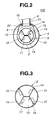
- an inner fin unit 13 of generally H-shaped cross section for promoting a heat transferring of the inner tube 2 and promoting a turbulent flow of EGR gas that flows in the cylindrical inner passage 12.
- the inner fin unit 13 comprises two identical channel-shaped fin plates 14 that are coupled in a back-to-back connection manner.
- the fin plates 14 are constructed of stainless steel. However, if desired, the fin plates 14 may be constructed of other metals that have a good heat transfer.
- each fin plate 14 is formed with flanged ends 15 and as is seen from Fig. 2, the flanged ends 15 are brazed to a cylindrical inner surface of the inner tube 2. As will be described in detail hereinafter, the two fin plates 14 are brazed to each other at their mutually contacting back portions.
- each fin plate 14 is formed with a plurality of slits 16 each extending in the direction of the width of the fin plate 14.
- Each slit 16 is formed at both end portions thereof with small slanted fins 17.
- the small slanted fins 17 possessed by each fin plate 14 comprise a first group of fins 17 that project inward from one side wall of the fin plate 14 and a second group of fins 17 that project outward from the other side wall of the fin plate 14, as will be understood from Fig. 4.
- the slits 16 With the slits 16, a thermal distortion of the inner fin unit 13 is suppressed or at least minimized. Furthermore, with the small slanted fins 17, the heat transfer area of the inner fin unit 13 is increased.
- the outer tube 4 comprises a cylindrical middle portion and radially depressed end portions 18 that have openings to which the inlet and outlet pipes 5 and 6 are connected. More specifically, the radially raised end portions 8 of the middle tube 3 and the radially depressed end portions 18 of the outer tube 4 are put on one another to mate the openings thereof to constitute pipe fixing openings 19, to which the base ends of the inlet and outlet pipes 5 and 6 are fixed.
- a hydraulic bulging method may be used for forming the radially raised and depressed portions 8 and 18.
- a caulking technique is employed for connecting the base ends of the inlet and outlet pipes 5 and 6 to the pipe fixing openings 19, a caulking technique is employed. Then, brazing is applied to such caulked portions to assure a tight connection as well as a hermetic sealing between the base ends of the pipes 5 and 6 and the pipe fixing openings 19.
- each pipe 5 or 6 has a bead portion 21 with a cylindrical leading end 22.
- the cylindrical leading end 22 of the pipe 5 or 6 is inserted into the pipe fixing opening 19, and then, with the bead portion 21 kept pressed against an upper peripheral edge of the opening 19, the cylindrical leading end 22 is pressed radially outward by using a suitable caulking tool. With this, the base end of each pipe 5 or 6 is caulked to the peripheral edge of the pipe fixing opening 19, as shown.
- the inner tube 2, the middle tube 3, the outer tube 4, the mounting flanges 7, the inlet and outlet pipes 5 and 6 are preliminarily united to constitute a so-called pre-assembled unit in such an arrangement as is shown in Fig. 1, and then this pre-assembled unit is put in a furnace, for example, vacuum furnace or the like, for a given time.
- brazing is carried out at the mutually contacting portions, viz., the portions between the mounting flanges 7 and the outer tube 4, the portions between the diametrically reduced ends 10 of the middle tube 3 and the inner tube 2, the portions between the caulked base ends of the inlet and outlet pipes 5 and 6 and the peripheral ends of the pipe fixing openings 19 of the outer and middle tubes 4 and 3, the portion between backs of the fin plates 14.
- Nickel brazing, Cupper brazing and the like are usable. That is, for such brazing, a suitable brazing filler metal plate or paste like filler metal material is previously set at or applied to the portions which are to be brazed. If desired, a clad metal lined with a brazing filler metal or a metal plated with a cupper may be used as a material of the members which are brazed.
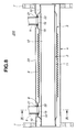
- Fig. 6 there is shown a finished product of the triple-tube type heat exchanger 100 of the first embodiment of the present invention.
- the inlet pipe 5 is connected to an outlet pipe of a radiator (not shown) and the outlet pipe 6 is connected to an inlet pipe of the radiator, and a left inlet end 100A of the outer tube 4 is connected to an exhaust system of an associated internal combustion engine and the right outlet end 100B of the tube 4 is connected to an intake system of the engine.
- cooling water viz., engine cooling water
- the EGR gas from the exhaust system of the engine is led into both the inner and outer gas flow passages 12 and 20 from the inlet end 100A of the outer tube 4 and discharged from the outlet end 100B of the same and introduced into the intake system of the engine, as is indicated by the blank arrows.
- the EGR gas is cooled by the cooling water. Because the outer tube 4 is exposed to the open air, the EGR gas flowing in the outer gas flow passage 20 is much effectively cooled as compared with that flowing in the inner gas flow passage 12.
- the caulked base ends of the inlet and outlet pipes 5 and 6 are neatly received in the circle that is possessed by the section of the outer tube 4, as shown in Fig. 2.
- the EGR gas flowing in the outer gas flow passage 20 is permitted to have a smoothed flow therein and thus the amount of particles collected around the caulked base ends of the pipes 5 and 6 can be minimized.
- the middle tube 3 with the radially raised end portions 8 is inserted into the outer tube 4 and put on the pipes 5 and 6 having the peripheral edges of the pipe fixing openings 19 thereof respectively seated on the peripheral edges of the pipe fixing openings 19 of the outer tube 4.
- the radially raised end portions 8 of the middle tube 3 intimately contact with the radially depressed end portions 18 of the outer tube 4 due to the positioning effect given by the base ends of the pipes 5 and 6, and at the same time, due to the positioning effect of the pipes 5 and 6, the middle and outer tubes 3 and 4 are concentrically arranged.
- the middle tube 3 has the diametrically reduced ends 10 previously formed.
- a suitable caulking tool (not shown) is inserted into the middle tube 3 to make a caulking to the cylindrical leading ends 22 of the pipes 5 and 6.
- a suitable caulking tool (not shown) is inserted into the middle tube 3 to make a caulking to the cylindrical leading ends 22 of the pipes 5 and 6.
- the peripheral edges of the pipe fixing openings 19 of the middle and outer tubes 3 and 4 are tightly secured to the base ends of the inlet and outlet pipes 5 and 6, as is understood from Fig. 2.
- the inlet and outlet pipes 5 and 6, the outer tube 4 and the middle tube 3 are united to constitute a first pre-assembled unit which has a so-called "self-holding structure".
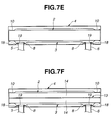
- the inner tube 2 is inserted into the middle tube 3 and as is seen from Fig. 7F, the two fin plates 14 are inserted into the inner tube 2 in such a manner as is seen from Fig. 5.
- the both ends of the inner tube 2 is intimately held by the diametrically reduced ends 10 of the middle tube 3 and the flanged ends 15 of the two fin plates 14 are intimately held by the inner tube 2 having the backs of the same intimately contacting each other, so that a second pre-assembled unit is constituted.
- suitable brazing filler metal plates or paste like filler metal material there have been previously set or provided suitable brazing filler metal plates or paste like filler metal material.
- the second pre-assembled unit is put in a furnace (viz., vacuum furnace or the like) for a given time to achieve brazing of the mutually contacting portion of the pre-assembled unit.
- a furnace viz., vacuum furnace or the like
- the triple-tube type heat exchanger 100 of the first embodiment is produced.
- the second pre-assembled unit has also "self-holding structure" due to the caulked connection of the pipes 5 and 6 to the middle and outer tubes 3 and 4, the intimate thrust connection of the inner tube 2 with the middle tube 3, and the intimate thrust connection of the two fin plates 14 with the inner tube 2.
- the brazing of the pre-assembled unit in the furnace can be carried out without usage of any positioning jigs.
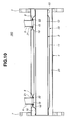
- a triple-tube type heat exchanger 200 which is a second embodiment of the present invention.
- the heat exchanger 200 of this second embodiment is substantially same as the above-mentioned heat exchanger 100 of the first embodiment except that in the second embodiment 200, the inner fin unit 13 is not provided.
- the middle tube 3 is of a corrugated type.
- the inner tube 2 and the outer tube 4 may be of the corrugated type.
- the inlet and outlet pipes 5 and 6 may be positioned at diametrically different and axially spaced portions of the outer tube 4.
- these pipes 5 and 6 may be positioned at diametrically opposite and axially spaced portions of the outer tube 4.
- a triple-tube type heat exchanger 300 which is a third embodiment of the present invention.
- the heat exchanger 300 of this third embodiment is substantially same as the above-mentioned heat exchanger 200 of the second embodiment except that in the third embodiment 300, the middle tube 3 is free of the corrugations 9.
- a triple-tube type heat exchanger 400 which is a fourth embodiment of the present invention.
- the heat exchanger 400 of this fourth embodiment is substantially same as the heat exchanger 300 of the third embodiment except that in the fourth embodiment 400, the inlet and outlet pipes 5 and 6 are positioned at diametrically opposed and axially spaced portions of the middle and outer tubes 3 and 4, as shown.
- the heat exchangers 200, 300 and 400 can also have a so-called “self holding structure", the brazing of their pre-assembled units can be carried out without usage of positioning jigs like in case of the first embodiment 100.
- fin plates 14 there are shown four types of fin plates which can be used as substitutes for the above-mentioned fin plates 14 in the present invention.
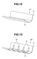
- a first modified fin plate 141 In Fig. 12, there is shown a first modified fin plate 141. In this modification, there are no construction and means that correspond to the slits 16 and the small slanted fins 17 employed in the fin plate 14 (see Fig. 4). Of course, when received in the inner tube 2, two fin plates 141 are used with their back portions intimately contacting with each other, as is seen from Fig. 14.
- a second modified fin plate 142 In this modification, only slits 16 are provided. Like in the first modified plate 141, two fin plates 142 are used when received in the inner tube 2.
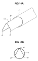
- a third modified fin plate 143 that is tightly installed in the inner tube 2.
- the third modified fin plate 143 has a generally V-shaped cross section including an apex part 23 and two inwardly bent flanged ends 25.
- the apex part 23 and the two flanged ends 25 are pressed against the cylindrical inner surface of the inner tube 2 because of the resiliency possessed by the fin plate 143.
- the fin plate 143 can have a so-called "self holding construction" in the inner tube 2.
- the three intimately contacting portions defined between the fin plate 143 and the inner tube 2 have been previously applied with suitable brazing filler metals or paste like filler metal material.
- the three intimately contacting portions are brazed to tightly fix the three parts 23 and 25 of the fin plate 143 to the outer tube 2.
- a fourth modified fin plate 144 that is tightly installed in the inner tube 2.
- the fourth modified fin plate 144 has a generally U-shaped cross section including two apex parts 26 and two inwardly bent flanged ends 35.
- the fin plate 144 can have the self holding construction in the inner tube 2.
- the four intimately contacting portions defined between the fin plate 144 and the inner tube 2 have been previously applied with suitable brazing filler metals or paste like filler metal material.
- the four intimately contacting portions are brazed to tightly fix the four parts 26 and 35 of the fin plate 144 to the inner tube 2.
- the above-mentioned third and fourth modified fin plates 143 and 144 may be provided with slits (16) and small slanted fins (17) like in case of the heat exchange 100 of the first embodiment (see Fig. 4).
- the inner and outer tubes 2 and 4 may be of a type that has a plurality of corrugations in order to increase the heat transfer area of the tubes.
Landscapes
- Engineering & Computer Science (AREA)
- Physics & Mathematics (AREA)
- Mechanical Engineering (AREA)
- General Engineering & Computer Science (AREA)
- Thermal Sciences (AREA)
- Chemical & Material Sciences (AREA)
- Combustion & Propulsion (AREA)
- Geometry (AREA)
- Heat-Exchange Devices With Radiators And Conduit Assemblies (AREA)
Applications Claiming Priority (4)
| Application Number | Priority Date | Filing Date | Title |
|---|---|---|---|
| JP2002230780 | 2002-08-08 | ||
| JP2002230780A JP2004069210A (ja) | 2002-08-08 | 2002-08-08 | 多重管式熱交換器およびその製造方法 |
| JP2002230779A JP4009157B2 (ja) | 2002-08-08 | 2002-08-08 | 熱交換器用エレメントチューブとそれを用いた熱交換器 |
| JP2002230779 | 2002-08-08 |
Publications (3)
| Publication Number | Publication Date |
|---|---|
| EP1388720A2 true EP1388720A2 (fr) | 2004-02-11 |
| EP1388720A3 EP1388720A3 (fr) | 2006-09-13 |
| EP1388720B1 EP1388720B1 (fr) | 2012-05-23 |
Family
ID=30447678
Family Applications (1)
| Application Number | Title | Priority Date | Filing Date |
|---|---|---|---|
| EP03018139A Expired - Lifetime EP1388720B1 (fr) | 2002-08-08 | 2003-08-08 | Echangeur de chaleur à triple tubes et sa méthode de fabrication |
Country Status (1)
| Country | Link |
|---|---|
| EP (1) | EP1388720B1 (fr) |
Cited By (7)
| Publication number | Priority date | Publication date | Assignee | Title |
|---|---|---|---|---|
| DE102006014188A1 (de) * | 2006-03-24 | 2007-09-27 | Behr Gmbh & Co. Kg | Vorrichtung zur Kühlung eines Abgasstroms |
| EP1995542A2 (fr) | 2007-05-24 | 2008-11-26 | Emiflex SpA | Dispositif échangeur de chaleur |
| CN102135382A (zh) * | 2010-01-21 | 2011-07-27 | 上海意发玛制药设备有限公司 | 管中管式换热器及换热器管路系统 |
| CN104634813A (zh) * | 2015-01-27 | 2015-05-20 | 中国科学院合肥物质科学研究院 | 一种传热系数可调式换热装置 |
| CN106401808A (zh) * | 2015-07-30 | 2017-02-15 | 高级英国公司 | 带散热片的共轴冷却器 |
| GB2559182A (en) * | 2017-01-30 | 2018-08-01 | Senior Uk Ltd | Finned coaxial cooler |
| US10995998B2 (en) | 2015-07-30 | 2021-05-04 | Senior Uk Limited | Finned coaxial cooler |
Families Citing this family (2)
| Publication number | Priority date | Publication date | Assignee | Title |
|---|---|---|---|---|
| JP2005249312A (ja) * | 2004-03-04 | 2005-09-15 | Denso Corp | 熱交換器用部材の組付け方法 |
| DE102012107908B4 (de) | 2012-08-28 | 2018-11-15 | Tenneco Gmbh | Abgaswärmetauscher |
Family Cites Families (10)
| Publication number | Priority date | Publication date | Assignee | Title |
|---|---|---|---|---|
| US2929408A (en) * | 1955-04-27 | 1960-03-22 | Acme Ind Inc | Fin construction |
| FR1162651A (fr) * | 1955-10-17 | 1958-09-16 | Modine Mfg Co | Perfectionnements aux structures d'échange de chaleur |
| US3889746A (en) * | 1973-12-14 | 1975-06-17 | Ernest Laffranchi | Heat exchanger |
| DE3515830A1 (de) * | 1985-05-02 | 1986-11-06 | Karl 8022 Grünwald Gercken | Verfahren und vorrichtung zur unterdrueckung der entgasung von kraftstoff in der kraftstoffversorgungsanlage eines kraftfahrzeugs |
| JP2875281B2 (ja) * | 1989-05-15 | 1999-03-31 | カルソニック株式会社 | ラジエータタンクへのオイルクーラの取付方法 |
| JPH0343653A (ja) * | 1989-07-08 | 1991-02-25 | Nippondenso Co Ltd | 燃料冷却装置 |
| JP3227876B2 (ja) * | 1993-03-26 | 2001-11-12 | 株式会社デンソー | 熱交換器 |
| JP3333638B2 (ja) * | 1994-08-09 | 2002-10-15 | ヤンマーディーゼル株式会社 | 排気ガス熱交換器 |
| JP4085402B2 (ja) * | 1998-04-29 | 2008-05-14 | 株式会社ティラド | オイルクーラとラジエータタンクとの接合方法 |
| KR20000024564A (ko) * | 2000-02-21 | 2000-05-06 | 유병재 | 열교환기용 파이프 |
-
2003
- 2003-08-08 EP EP03018139A patent/EP1388720B1/fr not_active Expired - Lifetime
Cited By (14)
| Publication number | Priority date | Publication date | Assignee | Title |
|---|---|---|---|---|
| US7478630B2 (en) | 2006-03-24 | 2009-01-20 | Behr Gmbh & Co. Kg | Device and method for cooling exhaust gas |
| DE102006014188A1 (de) * | 2006-03-24 | 2007-09-27 | Behr Gmbh & Co. Kg | Vorrichtung zur Kühlung eines Abgasstroms |
| EP1995542A2 (fr) | 2007-05-24 | 2008-11-26 | Emiflex SpA | Dispositif échangeur de chaleur |
| EP1995542A3 (fr) * | 2007-05-24 | 2009-07-08 | Emiflex SpA | Dispositif échangeur de chaleur |
| CN102135382A (zh) * | 2010-01-21 | 2011-07-27 | 上海意发玛制药设备有限公司 | 管中管式换热器及换热器管路系统 |
| CN104634813B (zh) * | 2015-01-27 | 2017-03-29 | 中国科学院合肥物质科学研究院 | 一种传热系数可调式换热装置 |
| CN104634813A (zh) * | 2015-01-27 | 2015-05-20 | 中国科学院合肥物质科学研究院 | 一种传热系数可调式换热装置 |
| CN106401808A (zh) * | 2015-07-30 | 2017-02-15 | 高级英国公司 | 带散热片的共轴冷却器 |
| EP3133363A1 (fr) * | 2015-07-30 | 2017-02-22 | Senior UK Limited | Refroidisseur coaxial à ailettes |
| CN106401808B (zh) * | 2015-07-30 | 2019-05-31 | 高级英国公司 | 带散热片的共轴冷却器 |
| US10995998B2 (en) | 2015-07-30 | 2021-05-04 | Senior Uk Limited | Finned coaxial cooler |
| US11029095B2 (en) | 2015-07-30 | 2021-06-08 | Senior Uk Limited | Finned coaxial cooler |
| GB2559182A (en) * | 2017-01-30 | 2018-08-01 | Senior Uk Ltd | Finned coaxial cooler |
| GB2559182B (en) * | 2017-01-30 | 2021-01-06 | Senior Uk Ltd | Finned heat exchangers |
Also Published As
| Publication number | Publication date |
|---|---|
| EP1388720B1 (fr) | 2012-05-23 |
| EP1388720A3 (fr) | 2006-09-13 |
Similar Documents
| Publication | Publication Date | Title |
|---|---|---|
| EP1764573B1 (fr) | Connection d'un échangeur de chaleur par bride | |
| US5036914A (en) | Vehicle-loaded parallel flow type heat exchanger | |
| CA2443496C (fr) | Echangeurs de chaleur a faisceau comprenant des tubes a extremite de section elargie | |
| WO2012116448A1 (fr) | Echangeur de chaleur gaz-liquide coaxial équipé d'un organe d'assemblage à dilatation thermique | |
| JPS63105400A (ja) | 熱交換器およびその組立て方法 | |
| US9593889B2 (en) | Heat exchanger construction | |
| US6173765B1 (en) | Heat exchange having header tank | |
| US5092398A (en) | Automotive parallel flow type heat exchanger | |
| EP1388720A2 (fr) | Echangeur de chaleur à triple tubes et sa méthode de fabrication | |
| JP2001215095A (ja) | 熱交換器 | |
| US7311138B2 (en) | Stacking-type, multi-flow, heat exchangers and methods for manufacturing such heat exchangers | |
| US20070000652A1 (en) | Heat exchanger with dimpled tube surfaces | |
| US8646516B2 (en) | Alternating plate headerless heat exchangers | |
| JPH11223477A (ja) | 自動車用複合型熱交換器およびその製造方法 | |
| JP2000220990A (ja) | 熱交換器 | |
| JPH09250888A (ja) | 2重管式熱交換器 | |
| EP2057434B1 (fr) | Échangeurs de chaleur sans colonne à plaques alternatives | |
| JP3151954B2 (ja) | 自動車用熱交換器 | |
| JP3387523B2 (ja) | 熱交換器製造方法、装入空気冷却器及び熱交換器 | |
| JP3259382B2 (ja) | 二重管型オイルクーラ | |
| JP2004069210A (ja) | 多重管式熱交換器およびその製造方法 | |
| JPH08219680A (ja) | 熱交換器 | |
| EP0977001A1 (fr) | Echangeur de chaleur | |
| JP4461010B2 (ja) | 製造が簡単な自動車専用ヘッダおよびヘッダボックスを有する熱交換器 | |
| JP3207321B2 (ja) | アルミニウム材製熱交換器 |
Legal Events
| Date | Code | Title | Description |
|---|---|---|---|
| PUAI | Public reference made under article 153(3) epc to a published international application that has entered the european phase |
Free format text: ORIGINAL CODE: 0009012 |
|
| AK | Designated contracting states |
Kind code of ref document: A2 Designated state(s): AT BE BG CH CY CZ DE DK EE ES FI FR GB GR HU IE IT LI LU MC NL PT RO SE SI SK TR |
|
| AX | Request for extension of the european patent |
Extension state: AL LT LV MK |
|
| RAP1 | Party data changed (applicant data changed or rights of an application transferred) |
Owner name: MAHLE FILTER SYSTEMS JAPAN CORPORATION |
|
| PUAL | Search report despatched |
Free format text: ORIGINAL CODE: 0009013 |
|
| AK | Designated contracting states |
Kind code of ref document: A3 Designated state(s): AT BE BG CH CY CZ DE DK EE ES FI FR GB GR HU IE IT LI LU MC NL PT RO SE SI SK TR |
|
| AX | Request for extension of the european patent |
Extension state: AL LT LV MK |
|
| 17P | Request for examination filed |
Effective date: 20061012 |
|
| AKX | Designation fees paid |
Designated state(s): DE ES FR GB HU IT |
|
| 17Q | First examination report despatched |
Effective date: 20080528 |
|
| GRAP | Despatch of communication of intention to grant a patent |
Free format text: ORIGINAL CODE: EPIDOSNIGR1 |
|
| GRAS | Grant fee paid |
Free format text: ORIGINAL CODE: EPIDOSNIGR3 |
|
| GRAA | (expected) grant |
Free format text: ORIGINAL CODE: 0009210 |
|
| AK | Designated contracting states |
Kind code of ref document: B1 Designated state(s): DE ES FR GB HU IT |
|
| REG | Reference to a national code |
Ref country code: GB Ref legal event code: FG4D |
|
| REG | Reference to a national code |
Ref country code: DE Ref legal event code: R096 Ref document number: 60340983 Country of ref document: DE Effective date: 20120719 |
|
| PG25 | Lapsed in a contracting state [announced via postgrant information from national office to epo] |
Ref country code: IT Free format text: LAPSE BECAUSE OF FAILURE TO SUBMIT A TRANSLATION OF THE DESCRIPTION OR TO PAY THE FEE WITHIN THE PRESCRIBED TIME-LIMIT Effective date: 20120523 |
|
| PLBE | No opposition filed within time limit |
Free format text: ORIGINAL CODE: 0009261 |
|
| STAA | Information on the status of an ep patent application or granted ep patent |
Free format text: STATUS: NO OPPOSITION FILED WITHIN TIME LIMIT |
|
| GBPC | Gb: european patent ceased through non-payment of renewal fee |
Effective date: 20120823 |
|
| PG25 | Lapsed in a contracting state [announced via postgrant information from national office to epo] |
Ref country code: ES Free format text: LAPSE BECAUSE OF FAILURE TO SUBMIT A TRANSLATION OF THE DESCRIPTION OR TO PAY THE FEE WITHIN THE PRESCRIBED TIME-LIMIT Effective date: 20120903 |
|
| 26N | No opposition filed |
Effective date: 20130226 |
|
| REG | Reference to a national code |
Ref country code: DE Ref legal event code: R097 Ref document number: 60340983 Country of ref document: DE Effective date: 20130226 |
|
| PG25 | Lapsed in a contracting state [announced via postgrant information from national office to epo] |
Ref country code: GB Free format text: LAPSE BECAUSE OF NON-PAYMENT OF DUE FEES Effective date: 20120823 |
|
| PG25 | Lapsed in a contracting state [announced via postgrant information from national office to epo] |
Ref country code: HU Free format text: LAPSE BECAUSE OF FAILURE TO SUBMIT A TRANSLATION OF THE DESCRIPTION OR TO PAY THE FEE WITHIN THE PRESCRIBED TIME-LIMIT Effective date: 20030808 |
|
| REG | Reference to a national code |
Ref country code: FR Ref legal event code: PLFP Year of fee payment: 14 |
|
| REG | Reference to a national code |
Ref country code: FR Ref legal event code: PLFP Year of fee payment: 15 |
|
| REG | Reference to a national code |
Ref country code: FR Ref legal event code: PLFP Year of fee payment: 16 |
|
| PGFP | Annual fee paid to national office [announced via postgrant information from national office to epo] |
Ref country code: DE Payment date: 20180829 Year of fee payment: 16 |
|
| PGFP | Annual fee paid to national office [announced via postgrant information from national office to epo] |
Ref country code: FR Payment date: 20190826 Year of fee payment: 17 |
|
| REG | Reference to a national code |
Ref country code: DE Ref legal event code: R119 Ref document number: 60340983 Country of ref document: DE |
|
| PG25 | Lapsed in a contracting state [announced via postgrant information from national office to epo] |
Ref country code: DE Free format text: LAPSE BECAUSE OF NON-PAYMENT OF DUE FEES Effective date: 20200303 |
|
| PG25 | Lapsed in a contracting state [announced via postgrant information from national office to epo] |
Ref country code: FR Free format text: LAPSE BECAUSE OF NON-PAYMENT OF DUE FEES Effective date: 20200831 |