EP1389032A2 - Unité de réception - Google Patents
Unité de réception Download PDFInfo
- Publication number
- EP1389032A2 EP1389032A2 EP03016321A EP03016321A EP1389032A2 EP 1389032 A2 EP1389032 A2 EP 1389032A2 EP 03016321 A EP03016321 A EP 03016321A EP 03016321 A EP03016321 A EP 03016321A EP 1389032 A2 EP1389032 A2 EP 1389032A2
- Authority
- EP
- European Patent Office
- Prior art keywords
- cavity
- receiver
- receiver unit
- case
- receiver body
- Prior art date
- Legal status (The legal status is an assumption and is not a legal conclusion. Google has not performed a legal analysis and makes no representation as to the accuracy of the status listed.)
- Withdrawn
Links
Images



Classifications
-
- H—ELECTRICITY
- H04—ELECTRIC COMMUNICATION TECHNIQUE
- H04R—LOUDSPEAKERS, MICROPHONES, GRAMOPHONE PICK-UPS OR LIKE ACOUSTIC ELECTROMECHANICAL TRANSDUCERS; ELECTRIC HEARING AIDS; PUBLIC ADDRESS SYSTEMS
- H04R1/00—Details of transducers, loudspeakers or microphones
-
- H—ELECTRICITY
- H04—ELECTRIC COMMUNICATION TECHNIQUE
- H04R—LOUDSPEAKERS, MICROPHONES, GRAMOPHONE PICK-UPS OR LIKE ACOUSTIC ELECTROMECHANICAL TRANSDUCERS; ELECTRIC HEARING AIDS; PUBLIC ADDRESS SYSTEMS
- H04R1/00—Details of transducers, loudspeakers or microphones
- H04R1/20—Arrangements for obtaining desired frequency or directional characteristics
- H04R1/22—Arrangements for obtaining desired frequency or directional characteristics for obtaining desired frequency characteristic only
- H04R1/28—Transducer mountings or enclosures modified by provision of mechanical or acoustic impedances, e.g. resonator, damping means
- H04R1/2807—Enclosures comprising vibrating or resonating arrangements
- H04R1/2838—Enclosures comprising vibrating or resonating arrangements of the bandpass type
- H04R1/2842—Enclosures comprising vibrating or resonating arrangements of the bandpass type for loudspeaker transducers
-
- H—ELECTRICITY
- H04—ELECTRIC COMMUNICATION TECHNIQUE
- H04M—TELEPHONIC COMMUNICATION
- H04M1/00—Substation equipment, e.g. for use by subscribers
- H04M1/02—Constructional features of telephone sets
- H04M1/03—Constructional features of telephone transmitters or receivers, e.g. telephone hand-sets
- H04M1/035—Improving the acoustic characteristics by means of constructional features of the housing, e.g. ribs, walls, resonating chambers or cavities
-
- H—ELECTRICITY
- H04—ELECTRIC COMMUNICATION TECHNIQUE
- H04R—LOUDSPEAKERS, MICROPHONES, GRAMOPHONE PICK-UPS OR LIKE ACOUSTIC ELECTROMECHANICAL TRANSDUCERS; ELECTRIC HEARING AIDS; PUBLIC ADDRESS SYSTEMS
- H04R1/00—Details of transducers, loudspeakers or microphones
- H04R1/20—Arrangements for obtaining desired frequency or directional characteristics
- H04R1/32—Arrangements for obtaining desired frequency or directional characteristics for obtaining desired directional characteristic only
- H04R1/34—Arrangements for obtaining desired frequency or directional characteristics for obtaining desired directional characteristic only by using a single transducer with sound reflecting, diffracting, directing or guiding means
- H04R1/345—Arrangements for obtaining desired frequency or directional characteristics for obtaining desired directional characteristic only by using a single transducer with sound reflecting, diffracting, directing or guiding means for loudspeakers
-
- H—ELECTRICITY
- H04—ELECTRIC COMMUNICATION TECHNIQUE
- H04R—LOUDSPEAKERS, MICROPHONES, GRAMOPHONE PICK-UPS OR LIKE ACOUSTIC ELECTROMECHANICAL TRANSDUCERS; ELECTRIC HEARING AIDS; PUBLIC ADDRESS SYSTEMS
- H04R2499/00—Aspects covered by H04R or H04S not otherwise provided for in their subgroups
- H04R2499/10—General applications
- H04R2499/11—Transducers incorporated or for use in hand-held devices, e.g. mobile phones, PDA's, camera's
Definitions
- the present invention relates to a receiver unit having a receiver body, and more particularly to a receiver unit having a receiver body in which a countermeasure for flattening the sound pressure characteristic is taken on the receiver unit itself.
- Fig. 7 is a view showing a conventional example.
- the reference numeral 1 denotes a receiver body
- 5 denotes a handset of a mobile information terminal device such as a portable telephone.
- the receiver body 1 is fitted into a positioning boss 51 of the handset 5 to be attached to the handset.
- a sound hole (not shown) which is disposed in the front side of the receiver body 1 is opposed to a sound hole 52 of the handset 5, and a cavity 53 of a large volume serving as the internal space of the handset 5 is positioned in the back portion of the receiver body 1.
- the cavity 53 serving as the internal space of the handset is often set to have a volume of, for example, about 10 cc.
- the sound pressure characteristic (sound pressure-frequency characteristic) in the state where the receiver body is attached to the handset 5 is often evaluated with using a leakage type artificial ear.
- a leakage type artificial ear In this case, in order to obtain a flat sound pressure characteristic, it is necessary to employ a cavity structure in which an adequate leakage path is formed in the back portion of the receiver body 1.
- the structure shown in Fig. 7 is an example of such a structure.
- Japanese Patent Application Laying-Open No. 61-139189 discloses a cavity structure in which a dynamic receiver (electrically conductive receiver) is used as a receiver body
- Japanese Patent Application Laying-Open No. 10-229435 discloses a cavity structure in which a piezoelectric receiver is used as a receiver body
- Japanese Patent Application Laying-Open No. 11-266489 discloses a cavity structure as a further prior art example.
- the internal space of the handset is used as a cavity in the same manner as that shown in Fig. 7.
- Japanese Patent Application Laying-Open No. 2000-49920 discloses a mobile information terminal device having a speaker assembly in which spaces are formed in the front and rear sides of a speaker, and the front and rear spaces are acoustically coupled with a third space.
- Japanese Patent No. 3,243,616 discloses a still further prior art example in which a cylindrical cylinder is placed between front and rear walls of a handset housing of a mobile information terminal device, and a partition to which an electroacoustic transducer is attached is placed in the cylindrical cylinder, thereby forming chambers (cavities) in front and back of the electroacoustic transducer.
- a cavity structure for improving the sound pressure characteristic is realized with using the internal space 53 of the handset 5 as a large-volume cavity.
- the invention has been conducted under the above circumstances. It is an object of the invention to provide a receiver unit having a structure in which the receiver unit itself is effective in flattening a sound pressure characteristic without depending on the internal volume of a handset of a mobile information terminal device.
- the receiver unit of the present invention is a receiver unit having a receiver body wherein the receiver unit has: the receiver body; and a cavity which is attached to an outer side of the receiver body to flatten a sound pressure characteristic of the receiver body.
- the sound pressure characteristic of the receiver body may be flattened by: adding the cavity to a back portion of the receiver body; adding the cavity to a front portion of the receiver body; or adding the cavity to each of back and front portions of the receiver body.
- the terms “adding the cavity to a back portion of the receiver body” mean that the receiver body itself comprises a cavity in the back portion of receiver body, and excludes a structure in which the internal space of the handset is in contact with the back face of the receiver body.
- the terms “adding the cavity to a front portion of the receiver body” mean that the receiver body itself comprises a cavity in the front portion of receiver body, and excludes a structure in which the internal space of the handset is in contact with the front face of the receiver body.
- the cavity is formed by an internal space of a case which houses the receiver body.
- the cavity is formed by an internal space of a case which houses the receiver body, and a through hole constituting a leakage path is formed in a wall of the case. According to the configuration, even when the cavity has a small volume, the flattening of the sound pressure characteristic can be remarkably attained as described above, so that the case can be easily miniaturized. This contributes to easiness of miniaturization of a device such as a handset.
- a resonant structure is added to the cavity.
- a resonant structure is added to the cavity, when the resonant structure is added to a front cavity of the receiver body, a sound pressure characteristic which has a dip in the vicinity of the resonance frequency is obtained.
- a sound pressure characteristic which has a peak in the vicinity of the resonance frequency is obtained.
- a flat sound pressure characteristic is obtained.
- the resonant structure comprises: a hollow chamber which is formed in the cavity by a partition wall; and a through hole which is opened in the partition wall to acoustically couple the cavity with the hollow chamber.
- the resonant structure is a Helmholtz resonant structure. The use of a Helmholtz resonant structure produces an advantage that the resonance frequency can be determined from the relationship between the size of the through hole of the partition wall and the volume of the hollow chamber.
- the sound pressure characteristic is based on evaluation using a leakage type artificial ear. This is because, as described at the beginning of the specification, a sound pressure characteristic is often evaluated with using a leakage type artificial ear.
- the cavity comprises a leakage path which acoustically communicates with an external space.
- the internal space of the handset of the device can be used as the external space which is to be acoustically coupled with the cavity via the leakage path.
- the external space is an internal space of a handset of a mobile information terminal device. According to the configuration, the flattening of the sound pressure characteristic can be easily expedited.
- an attachment piece for attaching the case to a handset of a mobile information terminal device may be molded integrally with the case. According to the configuration, the case can be attached to the handset via the attachment piece.
- the case may be housed in an electrically insulating holder having an opening through which a sound hole forming region of the receiver body is exposed, and the through hole is passed through the holder.
- the receiver unit itself can comprise a cavity structure for flattening the sound pressure characteristic. Furthermore, the sound pressure characteristic can be improved by causing the cavity of the receiver unit to acoustically communicate with the internal space of a device such as a handset through a leakage path. Even when the specification of the receiver body is modified, therefore, it is not required to change the design of a device such as a handset. Moreover, the occupying space for attachment can be made small, and hence miniaturization of the device such as a handset can be easily realized.
- the resonance structure is added to the front and/or back portion of the receiver unit, it is possible to attain the effect that a sound pressure characteristic which has a peak in the vicinity of the resonance frequency can be obtained, that which has a dip in the vicinity of the resonance frequency can be obtained, or a flat sound pressure characteristic can be obtained by using such a resonance structure.
- the external space which communicates with the cavity of the receiver unit via the leakage path is explicitly ensured in the device to which the receiver unit is to be attached, and where the external space is not explicitly ensured.
- the external space can be easily ensured simply by selecting the place where the through hole of the partition wall is formed, so as to be opposed to the internal space (the external space with respect to the cavity) which can be ensured in the device.
- Fig. 1A is a section view showing a receiver unit A which is an embodiment of the invention
- Fig. 1B is a section view showing a use state of the receiver unit A.
- the receiver unit A comprises a receiver body 1, and a case 2 which houses the receiver body 1.
- the receiver body 1 is coupled with the case 2 in a state where an outer peripheral portion of the front face of the receiver body 1 overlaps with the peripheral edge of an opening 21 formed in the case 2.
- the case 2 is preferably configured by a resin molded piece.
- the case 2 may have a circular shape in plan view, an oval or elliptic shape in plan view, or a rectangular or other polygonal shape in plan view.
- the receiver body 1 may be similarly shaped.
- the opening 21 performs a function of introducing a sound emitted from the receiver body 1 to the outside of the case 2.
- a cavity (back cavity) 22 which is formed by the internal space of the case 2, and which is in contact with the receiver body 1 is positioned in a back portion of the receiver body 1.
- the back cavity 22 is separated from the external space by the wall of the case, and a through hole 24 constituting a leakage path 23 for acoustically coupling the back cavity 22 with the external space is formed in the case wall.
- the place where the through hole 24 constituting the leakage path 23 is formed may be in any position of the case wall, and preferably in a place opposed to the internal space ensured in a mobile information terminal device such as a handset to which the receiver unit A is to be attached.
- a receiver of the known type such as a dynamic receiver or a piezoelectric receiver can be used as the receiver body 1.
- the receiver unit A shown in Fig. 1A is attached to, for example, an earpiece of the handset 5 of a portable telephone shown in Fig. 1B.
- the leakage path 23 which is formed by the through hole 24 of the case 2 acoustically couples the back cavity 22 with the internal space 53 of the handset 5 serving as the external space.
- Fig. 2A is a section view showing a receiver unit A which is another embodiment of the invention
- Fig. 2B is a section view showing a use state of the receiver unit A.
- the receiver unit A is different from the receiver unit of Fig. 1A in that an attachment piece 25 is formed integrally on the case 2.
- the case 2 can be attached to the handset 5 via the attachment piece 25.
- the other configuration is identical with that which has been described above with reference to Figs. 1A and 1B.
- Fig. 2B is different from Fig. 1B in that the internal space 53 of the handset 5 is not placed below the lower face of the case 2 but around the case 2.
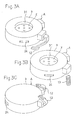
- Figs. 3A, 3B, and 3C exemplarily show several other embodiments.
- Figs. 3A and 3B are perspective views of the receiver unit A as viewed from the front side
- Fig. 3C is a perspective view of the receiver unit A as viewed from the rear side.
- the case 2 shown in Figs. 1A and 1B, or Figs. 2A and 2B is housed in an electrically insulating holder 3
- a through hole 24 constituting a leakage path 23 is passed through the holder 3
- the holder 3 comprises an opening 31 through which a sound hole forming region Z formed in the receiver body is exposed.
- Figs. 3 In the examples of Figs.
- terminals 12 each configured by a plate spring are projected from the holder 3, and, in the example of Fig. 3B, terminals 13 each configured by a coil spring are disposed.
- a resin or rubber molded piece can be preferably used as the holder 3.
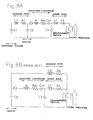
- Fig. 8A is a diagram showing an equivalent circuit of the cavity structure of the receiver unit A which has been described with reference to Fig. 2B
- Fig. 8B is a diagram showing an equivalent circuit of the conventional cavity structure which has been described with reference to Fig. 7.
- Fig. 9 is a graph of sound pressure characteristics which are obtained in simulations of the equivalent circuits.
- the solid line indicates the sound pressure characteristic of the cavity structure of the receiver unit A of Fig. 2 B, i.e., that of a small-volume receiver unit
- the broken line indicates the sound pressure characteristic of the conventional cavity structure of Fig. 7.
- Parameters in the simulations of the equivalent circuits are as follows.
- a flat characteristic which varies within 5 dB is obtained in the range from 400 Hz to 3.5 kHz as indicated by the solid line.
- a flat characteristic is obtained in the range from 300 Hz to 1 kHz as indicated by the broken line, but the sensitivity is lowered by 10 dB or more in the range from 1 kHz to 2 kHz.
- the back cavity has a volume of 10 cc.
- the back cavity in the case has a small volume of 0.25 cc, and also the volume (external volume) of the external space which communicates with the cavity via the leakage path is as small as 3 cc. Therefore, it will be seen that, in the receiver unit of the invention, a flat sound pressure characteristic can be obtained with using a small volume and miniaturization of a mobile information terminal device such as a handset equipped with the receiver unit of the invention can be easily realized.
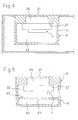
- Fig. 4 is a section view showing a use state of a receiver unit A of a still further embodiment of the invention.
- the receiver unit A comprises a receiver body 1, and a case 2 which houses the receiver body 1.
- the receiver unit has a front cavity 26 which is positioned in a front portion of the receiver body 1, in addition to a back cavity 22 which is in a back portion of the receiver body 1.
- an outer peripheral portion of the front face of the receiver body 1 is overlappingly coupled with a partition face 27 which separates the front and back cavities 26, 22 from each other, so that the front cavity 26 is positioned in a front portion of the receiver body 1, and the back cavity 22 is positioned in a back portion.
- the other configuration is identical with that shown in Figs. 1A and 1B. In the embodiment of Fig.
- a through hole constituting a leakage path for acoustically coupling the back cavity 22 with the external space may be formed in the wall of the case 2 of the receiver unit A.
- the place where the leakage path is formed may be in any position of the case wall, and preferably in a place opposed to the internal space ensured in a mobile information terminal device such as a handset to which the receiver unit A is to be attached.
- Fig. 5 is a section view showing a receiver unit A which is a still further embodiment of the invention.
- the receiver unit A is configured by adding a resonance structure 6 to the back cavity 22 which is formed by the case 2 of the receiver unit A that has been described with reference to Fig. 4.
- a partition wall 61 is disposed inside the back cavity 22 to reduce the volume of the back cavity 22.
- the resonance structure 6 is formed by a hollow chamber 62 which is formed by the partition wall 61, and a through hole 63 which is opened in the partition wall 61.
- the through hole 63 acoustically couples the back cavity 22 of the reduced volume with the hollow chamber 62.
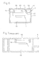
- Fig. 6 is a section view showing a receiver unit A which is a still further embodiment of the invention.
- the receiver unit A is configured by adding a resonance structure 7 to the front cavity 26 which is formed by the case 2 of the receiver unit A that has been described with reference to Fig. 4.
- a resonance structure 7 of the illustrated example an annular hollow chamber 72 is formed around the front cavity 26, a through hole 73 is opened in a partition wall 71 which separates the hollow chamber 72 from the front cavity 26, and the through hole 73 acoustically couples the front cavity 26 with the hollow chamber 72.
- Each of the resonance structures 6, 7 which have been described with reference to Figs. 5 and 6 is a Helmholtz resonant structure configured by the through hole 63 or 73 and the hollow chamber 62 or 72.
- the resonance frequency of the resonance structure 6 or 7 can be determined from the relationship between the size of the through hole 63 or 73 and the volume of the hollow chamber 62 or 72.
- a through hole constituting a leakage path for acoustically coupling the back cavity 22 with the external space may be formed.
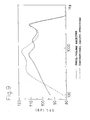
- Fig. 10 is a graph showing: a sound pressure characteristic which is obtained in simulation of the equivalent circuit of the example of Fig. 5, i.e., the receiver unit A in which the back cavity 22 is provided with the resonance structure 6; and that of a configuration in which the resonance structure 6 is omitted.
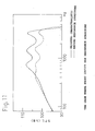
- Fig. 11 is a graph showing: a sound pressure characteristic which is obtained in simulation of the equivalent circuit of the example of Fig. 6, i.e., the receiver unit A in which the front cavity 26 is provided with the resonance structure 7, and that of a configuration in which the resonance structure 7 is omitted.
- the solid line indicates the sound pressure characteristic in the case where the resonance structure 6 or 7 is omitted
- the broken line indicates that in the case where the resonance structure 6 or 7 is provided.
- the receiver unit in which the back cavity 22 is provided with the resonance structure 6 has a sound pressure characteristic that is flatter in the range from 1 kHz to 3.5 kHz than the characteristic in the receiver unit where the back cavity 22 is not provided with the resonance structure, and that has a peak in the vicinity of the resonance frequency.
- the receiver unit in which the front cavity 26 is provided with the resonance structure has a sound pressure characteristic that is flatter in the range from 700 Hz to 3.5 kHz than the characteristic in the receiver unit where the front cavity 26 is not provided with the resonance structure, and that has a dip in the vicinity of the resonance frequency.
Landscapes
- Physics & Mathematics (AREA)
- Engineering & Computer Science (AREA)
- Acoustics & Sound (AREA)
- Signal Processing (AREA)
- Health & Medical Sciences (AREA)
- Otolaryngology (AREA)
- Telephone Set Structure (AREA)
- Obtaining Desirable Characteristics In Audible-Bandwidth Transducers (AREA)
- Audible-Bandwidth Dynamoelectric Transducers Other Than Pickups (AREA)
- Details Of Audible-Bandwidth Transducers (AREA)
Applications Claiming Priority (4)
| Application Number | Priority Date | Filing Date | Title |
|---|---|---|---|
| JP2002219884 | 2002-07-29 | ||
| JP2002219884 | 2002-07-29 | ||
| JP2003005809A JP2004129192A (ja) | 2002-07-29 | 2003-01-14 | レシーバユニット |
| JP2003005809 | 2003-01-14 |
Publications (2)
| Publication Number | Publication Date |
|---|---|
| EP1389032A2 true EP1389032A2 (fr) | 2004-02-11 |
| EP1389032A3 EP1389032A3 (fr) | 2009-03-04 |
Family
ID=30447661
Family Applications (1)
| Application Number | Title | Priority Date | Filing Date |
|---|---|---|---|
| EP03016321A Withdrawn EP1389032A3 (fr) | 2002-07-29 | 2003-07-18 | Unité de réception |
Country Status (6)
| Country | Link |
|---|---|
| US (1) | US20040017919A1 (fr) |
| EP (1) | EP1389032A3 (fr) |
| JP (1) | JP2004129192A (fr) |
| KR (1) | KR20040011352A (fr) |
| CN (1) | CN1476177A (fr) |
| TW (1) | TW200402982A (fr) |
Cited By (7)
| Publication number | Priority date | Publication date | Assignee | Title |
|---|---|---|---|---|
| US7508933B2 (en) | 2004-02-03 | 2009-03-24 | Benq Corporation | Resonance chamber of a cellular phone |
| EP1916869A3 (fr) * | 2006-10-25 | 2009-10-21 | LG Electronics Inc. | Haut-parleur monté dans un boîtier pour un dispositif de communication mobile |
| FR2934738A1 (fr) * | 2008-08-04 | 2010-02-05 | Sagem Comm | Combine telephonique sans fil ayant une chaine electroacoustique a large bande passante. |
| EP1791391A3 (fr) * | 2005-11-24 | 2010-09-22 | Samsung Electronics Co., Ltd. | Haut-parleur pour terminal de communication mobile |
| EP1883268A3 (fr) * | 2006-07-28 | 2011-05-04 | Samsung Electronics Co., Ltd. | Dispositif de haut-parleur pour terminal mobile |
| EP2866424A1 (fr) * | 2013-10-22 | 2015-04-29 | Nokia Corporation | Cavité arrière de haut-parleur |
| EP3133830A1 (fr) * | 2015-08-06 | 2017-02-22 | ACER Inc. | Haut-parleur et dispositif électronique comportant le haut-parleur |
Families Citing this family (15)
| Publication number | Priority date | Publication date | Assignee | Title |
|---|---|---|---|---|
| US7471846B2 (en) * | 2003-06-26 | 2008-12-30 | Fotonation Vision Limited | Perfecting the effect of flash within an image acquisition devices using face detection |
| US7966084B2 (en) * | 2005-03-07 | 2011-06-21 | Sony Ericsson Mobile Communications Ab | Communication terminals with a tap determination circuit |
| KR101196953B1 (ko) | 2005-10-06 | 2012-11-05 | 삼성전자주식회사 | 휴대용 단말기의 스피커 장치 |
| US8571227B2 (en) * | 2005-11-11 | 2013-10-29 | Phitek Systems Limited | Noise cancellation earphone |
| KR100897794B1 (ko) * | 2006-10-25 | 2009-05-15 | 엘지전자 주식회사 | 스피커 유닛 및 이를 구비한 휴대 단말기 |
| KR100854723B1 (ko) * | 2007-01-02 | 2008-08-27 | 주식회사 벨포원 | 마이크로스피커 |
| JP2008211389A (ja) * | 2007-02-23 | 2008-09-11 | Matsushita Electric Works Ltd | 通話装置 |
| US8666085B2 (en) * | 2007-10-02 | 2014-03-04 | Phitek Systems Limited | Component for noise reducing earphone |
| JP5255391B2 (ja) * | 2008-09-29 | 2013-08-07 | 京セラ株式会社 | 電子機器 |
| CN109874067A (zh) * | 2018-12-30 | 2019-06-11 | 瑞声科技(新加坡)有限公司 | 扬声器箱 |
| CN112738313A (zh) * | 2021-01-18 | 2021-04-30 | 闻泰通讯股份有限公司 | 听筒安装结构及终端设备 |
| US20220337927A1 (en) * | 2021-04-19 | 2022-10-20 | Plantronics, Inc. | Metamaterial To Scale Down Loudspeaker Enclosure Size And Enhance Performance |
| WO2024065623A1 (fr) * | 2022-09-30 | 2024-04-04 | Harman International Industries, Incorporated | Conception de cavité acoustique pour enceintes de haut-parleur |
| WO2024087006A1 (fr) * | 2022-10-25 | 2024-05-02 | 深圳市韶音科技有限公司 | Haut-parleur |
| CN119156835A (zh) * | 2022-10-28 | 2024-12-17 | 深圳市韶音科技有限公司 | 扬声器 |
Family Cites Families (10)
| Publication number | Priority date | Publication date | Assignee | Title |
|---|---|---|---|---|
| US5402486A (en) * | 1993-12-29 | 1995-03-28 | Wang; Xinxin | Earring compatible telephone handset receiver |
| JP3144230B2 (ja) * | 1994-09-01 | 2001-03-12 | 松下電器産業株式会社 | 低音再生スピーカ |
| JP3627343B2 (ja) * | 1995-02-06 | 2005-03-09 | 松下電器産業株式会社 | スピーカ装置 |
| US5729605A (en) * | 1995-06-19 | 1998-03-17 | Plantronics, Inc. | Headset with user adjustable frequency response |
| JP3560726B2 (ja) * | 1996-04-11 | 2004-09-02 | スター精密株式会社 | 小型電気音響変換器 |
| FR2755813B1 (fr) * | 1996-11-14 | 1998-12-11 | Alsthom Cge Alcatel | Combine telephonique |
| FI973892L (fi) * | 1997-10-06 | 1999-04-07 | Nokia Mobile Phones Ltd | Menetelmä ja järjestely kuulokkeen vuotosiedon parantamiseksi |
| US6002949A (en) * | 1997-11-18 | 1999-12-14 | Nortel Networks Corporation | Handset with a single transducer for handset and handsfree functionality |
| US6389145B2 (en) * | 1998-07-24 | 2002-05-14 | Agere Systems Guardian Corp. | Methods and apparatus for controlling the output of moving armature transducers |
| US8463334B2 (en) * | 2002-03-13 | 2013-06-11 | Qualcomm Incorporated | Apparatus and system for providing wideband voice quality in a wireless telephone |
-
2003
- 2003-01-14 JP JP2003005809A patent/JP2004129192A/ja active Pending
- 2003-06-25 KR KR1020030041589A patent/KR20040011352A/ko not_active Withdrawn
- 2003-06-27 TW TW092117728A patent/TW200402982A/zh unknown
- 2003-07-17 US US10/620,383 patent/US20040017919A1/en not_active Abandoned
- 2003-07-18 EP EP03016321A patent/EP1389032A3/fr not_active Withdrawn
- 2003-07-29 CN CNA031523404A patent/CN1476177A/zh active Pending
Cited By (17)
| Publication number | Priority date | Publication date | Assignee | Title |
|---|---|---|---|---|
| US7508933B2 (en) | 2004-02-03 | 2009-03-24 | Benq Corporation | Resonance chamber of a cellular phone |
| US7869617B2 (en) | 2005-11-24 | 2011-01-11 | Samsung Electronics Co., Ltd. | Speaker for mobile communication terminal |
| EP1791391A3 (fr) * | 2005-11-24 | 2010-09-22 | Samsung Electronics Co., Ltd. | Haut-parleur pour terminal de communication mobile |
| US8331599B2 (en) | 2006-07-28 | 2012-12-11 | Samsung Electronics Co., Ltd. | Speaker device for mobile terminal |
| EP1883268A3 (fr) * | 2006-07-28 | 2011-05-04 | Samsung Electronics Co., Ltd. | Dispositif de haut-parleur pour terminal mobile |
| EP2466913A1 (fr) * | 2006-10-25 | 2012-06-20 | LG Electronics Inc. | Haut-parleur monté dans une enceinte pour dispositif de communication mobile |
| US8005517B2 (en) | 2006-10-25 | 2011-08-23 | Lg Electronics Inc. | Mobile communication device |
| EP1916869A3 (fr) * | 2006-10-25 | 2009-10-21 | LG Electronics Inc. | Haut-parleur monté dans un boîtier pour un dispositif de communication mobile |
| USRE44942E1 (en) | 2006-10-25 | 2014-06-10 | Lg Electronics Inc. | Mobile communication device |
| WO2010015741A3 (fr) * | 2008-08-04 | 2010-04-01 | Sagem Communications Sas | Combine telephonique sans fil ayant une chaine electroacoustique a large bande passante |
| FR2934738A1 (fr) * | 2008-08-04 | 2010-02-05 | Sagem Comm | Combine telephonique sans fil ayant une chaine electroacoustique a large bande passante. |
| EP2866424A1 (fr) * | 2013-10-22 | 2015-04-29 | Nokia Corporation | Cavité arrière de haut-parleur |
| EP3021560A1 (fr) * | 2013-10-22 | 2016-05-18 | Nokia Technologies Oy | Cavité arrière de haut-parleur |
| US9386134B2 (en) | 2013-10-22 | 2016-07-05 | Nokia Corporation | Speaker back cavity |
| US9800969B2 (en) | 2013-10-22 | 2017-10-24 | Nokia Technologies Oy | Speaker back cavity |
| US10027784B2 (en) | 2013-10-22 | 2018-07-17 | Nokia Technologies Oy | Speaker back cavity |
| EP3133830A1 (fr) * | 2015-08-06 | 2017-02-22 | ACER Inc. | Haut-parleur et dispositif électronique comportant le haut-parleur |
Also Published As
| Publication number | Publication date |
|---|---|
| EP1389032A3 (fr) | 2009-03-04 |
| US20040017919A1 (en) | 2004-01-29 |
| TW200402982A (en) | 2004-02-16 |
| CN1476177A (zh) | 2004-02-18 |
| JP2004129192A (ja) | 2004-04-22 |
| KR20040011352A (ko) | 2004-02-05 |
Similar Documents
| Publication | Publication Date | Title |
|---|---|---|
| EP1389032A2 (fr) | Unité de réception | |
| CN113099364B (zh) | 电子设备 | |
| US7099484B2 (en) | Behind-the-ear hearing aid | |
| KR100540678B1 (ko) | 휴대용 통신 단말장치 및 그에 사용되는 전기 음향 변환기 | |
| KR101983792B1 (ko) | 휴대용 단말기의 스피커 모듈 | |
| US7505602B2 (en) | Mobile device with improved acoustic porting | |
| US11363370B2 (en) | Receiver module integrated with duct | |
| KR100629033B1 (ko) | 전기-음향 통신 유닛 | |
| KR102266425B1 (ko) | 사각 형상의 마이크로 스피커 | |
| JP2003502967A (ja) | 耳後方取付補聴器 | |
| CN113225653A (zh) | 发声器件和电子设备 | |
| CN216356802U (zh) | 一种移动终端设备 | |
| CN101222784B (zh) | 音箱结构及采用该音箱结构的移动电子设备 | |
| US11336983B1 (en) | Receiver module having pressure equilibrium structure | |
| CN101212838B (zh) | 音箱结构及采用该音箱结构的移动电子设备 | |
| CN218634230U (zh) | 发声装置以及电子设备 | |
| US7139394B2 (en) | Leak-tolerant handsfree telephone | |
| CN115623107B (zh) | 扬声器模组及终端设备 | |
| US20050123159A1 (en) | Portable accoustic apparatus | |
| KR100768137B1 (ko) | 마이크로스피커 모듈의 백볼륨 단자구조 | |
| EP0944220B1 (fr) | Dispositif de montage d'un diaphragme acoustique dans des radiotéléphones | |
| CN102227124A (zh) | 具有偏移声音开口的手持电子设备 | |
| JP2001309007A (ja) | 電気音響変換器 | |
| KR100656660B1 (ko) | 듀얼 스피커 모듈의 구조 | |
| JP3073664U (ja) | 自動車電話用喉振動制御式圧電マイクロホン |
Legal Events
| Date | Code | Title | Description |
|---|---|---|---|
| PUAI | Public reference made under article 153(3) epc to a published international application that has entered the european phase |
Free format text: ORIGINAL CODE: 0009012 |
|
| AK | Designated contracting states |
Kind code of ref document: A2 Designated state(s): AT BE BG CH CY CZ DE DK EE ES FI FR GB GR HU IE IT LI LU MC NL PT RO SE SI SK TR |
|
| AX | Request for extension of the european patent |
Extension state: AL LT LV MK |
|
| PUAL | Search report despatched |
Free format text: ORIGINAL CODE: 0009013 |
|
| AK | Designated contracting states |
Kind code of ref document: A3 Designated state(s): AT BE BG CH CY CZ DE DK EE ES FI FR GB GR HU IE IT LI LU MC NL PT RO SE SI SK TR |
|
| AX | Request for extension of the european patent |
Extension state: AL LT LV MK |
|
| RIC1 | Information provided on ipc code assigned before grant |
Ipc: H04M 1/03 20060101ALI20090128BHEP Ipc: H04R 1/34 20060101ALI20090128BHEP Ipc: H04R 1/28 20060101ALI20090128BHEP Ipc: H04R 1/38 20060101AFI20031108BHEP |
|
| STAA | Information on the status of an ep patent application or granted ep patent |
Free format text: STATUS: THE APPLICATION IS DEEMED TO BE WITHDRAWN |
|
| 18D | Application deemed to be withdrawn |
Effective date: 20090203 |