EP1391167A2 - Bewegbares Regal und Trennungssystem - Google Patents
Bewegbares Regal und Trennungssystem Download PDFInfo
- Publication number
- EP1391167A2 EP1391167A2 EP03004154A EP03004154A EP1391167A2 EP 1391167 A2 EP1391167 A2 EP 1391167A2 EP 03004154 A EP03004154 A EP 03004154A EP 03004154 A EP03004154 A EP 03004154A EP 1391167 A2 EP1391167 A2 EP 1391167A2
- Authority
- EP
- European Patent Office
- Prior art keywords
- wheels
- set forth
- floor
- pair
- drive
- Prior art date
- Legal status (The legal status is an assumption and is not a legal conclusion. Google has not performed a legal analysis and makes no representation as to the accuracy of the status listed.)
- Withdrawn
Links
Images






Classifications
-
- E—FIXED CONSTRUCTIONS
- E04—BUILDING
- E04B—GENERAL BUILDING CONSTRUCTIONS; WALLS, e.g. PARTITIONS; ROOFS; FLOORS; CEILINGS; INSULATION OR OTHER PROTECTION OF BUILDINGS
- E04B2/00—Walls, e.g. partitions, for buildings; Wall construction with regard to insulation; Connections specially adapted to walls
- E04B2/74—Removable non-load-bearing partitions; Partitions with a free upper edge
- E04B2/82—Removable non-load-bearing partitions; Partitions with a free upper edge characterised by the manner in which edges are connected to the building; Means therefor; Special details of easily-removable partitions as far as related to the connection with other parts of the building
- E04B2/827—Partitions constituted of sliding panels
-
- A—HUMAN NECESSITIES
- A47—FURNITURE; DOMESTIC ARTICLES OR APPLIANCES; COFFEE MILLS; SPICE MILLS; SUCTION CLEANERS IN GENERAL
- A47B—TABLES; DESKS; OFFICE FURNITURE; CABINETS; DRAWERS; GENERAL DETAILS OF FURNITURE
- A47B53/00—Cabinets or racks having several sections one behind the other
- A47B53/02—Cabinet systems, e.g. consisting of cabinets arranged in a row with means to open or close passages between adjacent cabinets
Definitions
- This invention relates to a moveable shelf and partitioning system and more particularly to an improved type of moveable shelving and partitioning system that offers greater flexibility and versatility than those presently in use.
- a first feature of the invention is adapted to be embodied in a storage arrangement comprising a shelf adapted to receive articles.
- the shelf has a base and a drive unit disposed beneath the base and adapted to support the shelf on a floor for movement there along.
- the drive unit is comprised of a pair of wheels supported for rotation upon the base about parallel, spaced axes.
- a drive and support belt is trained around the wheels and has a lower flight for engaging the floor and supporting the shelf thereupon.
- the drive unit further includes a drive for rotating at least one of the wheels for driving the belt and effecting movement of the shelf along the floor.
- Another feature of the invention is adapted to be embodied in a room partitioning system for partitioning an area having a floor and enclosing, fixed walls.
- the partitioning system comprises a panel supported on the floor by a drive system.
- the drive system being operable to move said panel along the floor in directions to partition the area into segments of the desired size and shape.
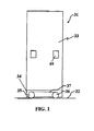
- FIG. 1 is a side elevational view of a moveable partitioning and shelving system constructed in accordance with a first embodiment of the invention.
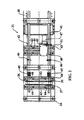
- FIGS. 2, 3 and 4 are bottom views of the supporting frame for the shelf shown in FIG. 1 looking at the left-hand edge, the center and the right-hand edge, respectively.
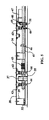
- FIGS. 5, 6 and 7 are side elevational views of the frame supporting portion showing the same areas illustrated in FIGS. 2, 3 and 4, respectively.
- FIG. 8 is a top plan view showing two pairs of drive belts.
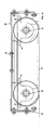
- FIG. 9 is a side elevational view of the drive belts.
- FIG. 10 is a view, in part similar to FIG. 9, but only shows one drive belt and in another type of arrangement therefore.
- FIG. 11 is a cross sectional view taken along the line 11-11 of FIG. 10.
- FIG. 12 is a view, in part similar to FIG. 9, and shows another embodiment of the invention and illustrates the arrangement supported on the floor.
- FIG. 13 is a graphical view showing how the driving load depends upon the width of the drive belt.
- FIG. 14 is an enlarged view, in part similar to FIG. 10, and shows how the drive belt supports the shelving and acts as a cushion between the driving wheels and the floor.
- FIG. 15 is a view, in part similar to FIG. 3, but shows another embodiment of the invention.
- FIG. 16 is a view looking in the direction of the arrow 16 in FIG. 15.
- FIG. 17 is a view looking the direction of the arrow 17 in FIG. 15 and is in part similar to FIG. 6.
- FIG. 18 is a perspective view showing a room having a moveable partition system constructed in accordance with another embodiment of the invention.
- FIGS. 19 through 21 are top plan views of a room divided into various configurations by a partitioning system constructed in accordance with yet another embodiment of the invention.
- a moveable shelf constructed in accordance with this embodiment of the invention is identified generally by the reference numeral 31.
- the moveable shelf 31 is adapted to be supported for movement along a floor 32 of any common type in a manner to be described.
- the shelf 31 includes an upper shelf assembly 33 that is mounted on a base, indicated generally by the reference numeral 34.
- the shelf assembly 33 can be of any material and construction and, for example, can include adjustable shelves that are held by side pieces. Since those skilled in the art will readily understand the various forms that the shelving may take, further description of that is believed to be unnecessary.
- the base 34 has a construction as best shown and as will be described later by reference to FIGS. 2 through 7. However, it includes driving wheels 35 and driven wheels 36 that are interconnect by an endless belt 37 which provides the direct support for the shelf 31 on the floor 32.
- the base 34 is comprised of a sheet metal assembly comprised of a planar type upper surface 38 and a pair of folded down side surfaces. Reinforcing U-channels 39 may be affixed at spaced locations along the horizontal surface 38 to add rigidity to the construction.
- a driving shaft 41 and driven shaft 42 are journaled in spaced transverse relationship by means of a plurality of pillow blocks 43 that are affixed to and form a part of the base 34. Specifically, these pillow blocks 43 are fixed to the under side of the panel surface 38. Bearings 44 carried by these pillow blocks 43 complete the journaling of the shafts 41 and 42 in the base 34.
- the driving wheels 35 are affixed at spaced locations and between pairs of the pillow blocks 43 and bearings 44 to the driving shaft 41.
- the driven wheels 36 are affixed to the driven shaft 42.
- the shafts 41 and 42 need not be continuous shafts but can constitute shaft segments that are joined together by couplings 45.
- the drive belts 37 may be of the toothed type and can cooperate with sprocket teeth on the driving wheels 35 and driven wheels 36.
- a plurality of sprockets 46 may be fixed along the lengths of the shafts 41 and 42 and interconnected by a chain (not shown).
- the driving shaft 41 is driven by one or more electric motors 47 that are mounted on a mounting bracket assembly 48 on the underside of the plate 38. These electric motors 47 have pinion gears 49 affixed to their drive shafts. The pinion gears 49 cooperate with gears 51 fixed to the driving shaft 41 so as to drive it. These motors 47 are of the reversible variable speed type and are control by a suitable control panel 49 mounted on the side of the shelves 31 (FIG. 1).
- the drive belts 37 may be made of any suitable material and my, as noted above, have their inner flight toothed to provide a non-slip driving relationship with the driving wheels 35 and driven wheel 36, it may be desirable to provide an arrangement for retaining the drive belt against axial movements.
- FIGS. 10 and 11 show an embodiment to how this may be accomplished. Aside from this anti-slipping arrangement, the construction is the same as that previously described and, therefore, the components which are the same have been identified by the same reference numerals and will not be described again, except insofar as is necessary to understand the construction and operation of this embodiment.
- the driving and driven wheels 35 and 36 have annular members 51 affixed to their outer periphery and which extend radially outwardly beyond the outer periphery of the wheels 35 and 36.
- annular members 51 affixed to their outer periphery and which extend radially outwardly beyond the outer periphery of the wheels 35 and 36.
- FIG. 12 shows such an arrangement where, in addition to the driving wheel 35 and driven wheel 36 mounted on the shafts 41 and 42, respectively, there are a plurality of back up rollers 61 that are carried by shafts 62 that are journaled in the pillow blocks 43 and bearings 44. Thus, more back up contact is provided between the drive belt 37 and the floor 32.
- the width of the belts 37 may be changed from a narrow width to a wide width as shown in FIG. 13 where the different widths are shown at 37a, 37b and 37c. Although the support is greater when the width is increased, this provides a larger resistance to driving and requires larger driving motors.
- FIG. 14 shows how the inter-positioning of the belt 37 between the driving and driven wheels 35 and 36 and the floor 32 provides a cushioning between the wheels 35 and 36 and the floor 32.
- the device can be utilized on a wide variety of floor materials and, special rails embedded in or mounted on the floor 32 are not required.
- the supporting portion of the drive belt is indicated in FIG. 14 by the reference numeral 63.
- FIGS. 15 through 17 are partial views which can be considered to be similar to FIGS. 3 and 6 and show how some wheels, again indicated by the reference numerals 35 and 36, can be mounted on stub shafts 81 which are journaled in the pillow blocks 43 and bearings 44. In this case, these drive belts 37 are only driven through their contact with the floor.
- FIGS. 18 and 19 through 21 show two such embodiments.
- a room indicated generally by the reference numeral 101 has a generally rectangular floor 102 closed by two long side walls 103 and 104 and two shorter end walls 105 and 106.
- the room is closed by a roof which is not illustrated.
- a partitioning assembly comprised of a first partition, indicated generally by the reference numeral 107 and a second partition indicated generally by the reference numeral 108 are supported for movement along the floor 102 by any of the types of drives previously described and particularly those shown in the earlier figures. Since the driving arrangement is the same at that previously described, it is not illustrated since it is not believed that a further illustration is necessary for those skilled in the art to understand this feature of the invention.
- each partition 107 and 108 has the same overall configuration and they are of a width that spans the width of the room 101.
- access to the two room areas that are formed when the partitions 107 and 108 in back-to-back relationship can be accessed through side doors 109 and 111.
- the partitions 107 and 108 can be moved together to vary the sizes of the room areas thus formed.
- the partitions 107 and 108 can be moved toward and away from each other to provide a third room area between the two partitions 107 and 108.
- the area between the two partitions can be accessed through either the door 112 and the partition 107 from one outer room area or through the door 112 in the partition 108 from the remaining outer area of the room.
- partition areas 113 and 114 On the sides of the partitions 107 and 108 outwardly from the doors 112, there are further areas provided indicated by the reference numerals 113 and 114. These partition areas 113 and 114 may be provided with shelving for storage, bookshelves, lockers or other types of storage systems.
- the partitions 107 and 108 move so that they are maintained in parallel relationship to each other and to the end walls 105 and 106.
- guide strips 115 are provided in the area above the partitions 107 and 108 and are sensed by appropriate sensors carried by the partitions 107 and 108. These sensors transmit signals to the drive motors, assuming a separate motor is utilized for each side of the partitions 107 and 108, so that they will be maintained in parallel relationship not only to each other but to the end walls 105 and 106.
- FIGS. 19 through 21 show another type of arrangement which can offer more flexibility in the partitioning of a room.
- the room again identified by the reference numeral 101 is also formed by two long side walls 103 and 104 and two shorter end walls 105 and 106. Along one of the walls, such as the side wall 103, there may be formed one or more vertical pillars 121 for a purpose which will be described shortly.
- the side wall 104 is formed with two doors, an outwardly opening door 122 and an inwardly opening door 123, both of which offer access to the room 101.
- a first shorter end wall partition, indicated generally by the reference numeral 124 is supported in any of the manners previously described. This partition is maintained in parallel relationship to the end walls 105 and 106.
- a second moveable partition 125 that is longer than the partition is supported in any of the manners previously described. This second partition 125 is maintained in a position parallel to the side walls 103 and 104.
- the partition 124 also includes at one of its ends a door 126 which may be swung to an outward position as shown in the figures or to an inward position flush with the end wall of the partition 124.
- the partition 125 is provided with two doors that open a common opening and which will be described shortly.
- FIG. 19 shows the partitions 124 and 125 in a position wherein they do not divide the room 101 into separate areas. Shelves or other types of storage arrangements are formed in the partitions 124 and 125 and can be accessed though the sides facing the interior of the room 101 for storage purposes.
- FIG. 20 shows another position of the partition 124 with the door 126 swung to an extended position.
- the door 126 effectively separates the two areas A and B formed by the moved partition 124.
- the room area A can be accessed from the outside through the door 122 or from the area B by the opening of the door 126 to a flush position against the end wall of the partition 124.
- the area B can be accessed through the outside by opening the door 123.
- the partition 125 can also be moved transversely relative to the partition 124 to a position as shown in FIG. 21 to divide the area into the previously area B and two new areas, C and D.
- doors 127 and 128 are formed in the partition 125 so as to permit access between the areas C and D.
- the area C can communicate with the area A by opening the door 126 and the entire areas can be accessed from the outside through either door 122 or 126.
- the area above the partitions 125 and 126 is also provided with guide strips and the partitions 124 and 125 provided with sensors so as to move always parallel to the walls 105 and 106 and 103 and 104, respectively.
- a number of embodiments of moveable storage racks and/or partitions that can be installed in existing buildings without the necessity of installing guide rails for them.
- the movement may be controlled so that the partitions move either in a parallel fashion or they can be rotated through an arc.
- the partitions are supported on drive and guide belts that are mounted on the underside thereof and which eliminate the need for the guide rails and spread the weight of the partition over a greater area of the floor so as to permit use in buildings which were not originally designed for such systems.
Landscapes
- Engineering & Computer Science (AREA)
- Architecture (AREA)
- Physics & Mathematics (AREA)
- Electromagnetism (AREA)
- Civil Engineering (AREA)
- Structural Engineering (AREA)
- Warehouses Or Storage Devices (AREA)
- Power-Operated Mechanisms For Wings (AREA)
Priority Applications (1)
| Application Number | Priority Date | Filing Date | Title |
|---|---|---|---|
| EP05028182A EP1654958A1 (de) | 2002-08-23 | 2003-02-26 | Bewegbares Regal und Trennungssystem |
Applications Claiming Priority (4)
| Application Number | Priority Date | Filing Date | Title |
|---|---|---|---|
| JP2002243984 | 2002-08-23 | ||
| JP2002243984A JP3909519B2 (ja) | 2002-08-23 | 2002-08-23 | レールレス可動間仕切り |
| US10/248,686 US20040035060A1 (en) | 2002-08-23 | 2003-02-09 | Moveable shelf and partitioning system |
| US248686 | 2003-02-09 |
Related Child Applications (1)
| Application Number | Title | Priority Date | Filing Date |
|---|---|---|---|
| EP05028182A Division EP1654958A1 (de) | 2002-08-23 | 2003-02-26 | Bewegbares Regal und Trennungssystem |
Publications (2)
| Publication Number | Publication Date |
|---|---|
| EP1391167A2 true EP1391167A2 (de) | 2004-02-25 |
| EP1391167A3 EP1391167A3 (de) | 2004-04-21 |
Family
ID=31190392
Family Applications (1)
| Application Number | Title | Priority Date | Filing Date |
|---|---|---|---|
| EP03004154A Withdrawn EP1391167A3 (de) | 2002-08-23 | 2003-02-26 | Bewegbares Regal und Trennungssystem |
Country Status (4)
| Country | Link |
|---|---|
| US (1) | US20070132200A1 (de) |
| EP (1) | EP1391167A3 (de) |
| CN (1) | CN100439613C (de) |
| TW (1) | TWI274719B (de) |
Cited By (3)
| Publication number | Priority date | Publication date | Assignee | Title |
|---|---|---|---|---|
| GB2421176A (en) * | 2004-12-14 | 2006-06-21 | Spacesaver Corp | Wheel assembly |
| FR3109165A1 (fr) * | 2020-04-08 | 2021-10-15 | Acoudesign | Dispositif multifonctions de modulation d’un espace ou zone dedie(e) a une activite |
| ES3042575A1 (es) * | 2024-05-21 | 2025-11-21 | Ugnius Remeika | Sistema para el desplazamiento de mobiliario |
Families Citing this family (2)
| Publication number | Priority date | Publication date | Assignee | Title |
|---|---|---|---|---|
| ES2908634T3 (es) * | 2017-11-24 | 2022-05-03 | Antonello Briosi | Bastidor modular para estanterías |
| CN109372158B (zh) * | 2018-10-25 | 2020-06-26 | 奥斯德诺建筑装饰制品(上海)有限公司 | 一种可改变位置的隔断墙 |
Family Cites Families (18)
| Publication number | Priority date | Publication date | Assignee | Title |
|---|---|---|---|---|
| FR1103510A (fr) * | 1954-04-17 | 1955-11-03 | Système de cloisons déplaçables | |
| FR1338820A (fr) * | 1961-11-10 | 1963-09-27 | Electrolux Ab | Installation pour l'emmagasinage d'objets, par exemple dans les entrepôts, salle d'archives ou analogues |
| US3398806A (en) * | 1966-05-12 | 1968-08-27 | Alvin L. Hendricks | Self-propelled crawler-type mobile platform |
| FR1550222A (de) * | 1967-09-25 | 1968-12-20 | ||
| FR1584837A (de) * | 1968-09-25 | 1970-01-02 | ||
| US3724397A (en) * | 1971-08-02 | 1973-04-03 | F Sargent | Endless track vehicles |
| US4123126A (en) * | 1977-08-04 | 1978-10-31 | Andrew Wilson Company | Compact shelving apparatus |
| US4360991A (en) * | 1980-09-09 | 1982-11-30 | West Evelyn M | Movable room dividing partition |
| FR2547635B1 (fr) * | 1983-06-16 | 1985-11-08 | Sansen Sa | Dispositif d'entrainement de chariot et ensembles mobiles pourvus d'un tel dispositif utilise pour le deplacement de travees mobiles de meubles de stockage |
| US4984737A (en) * | 1989-02-24 | 1991-01-15 | Spacesaver Corporation | Mobile shelving apparatus |
| US5072838A (en) * | 1989-04-26 | 1991-12-17 | Engineered Data Products, Inc. | Tape cartridge storage system |
| US5058507A (en) * | 1990-02-26 | 1991-10-22 | Spacesaver Corporation | Carriage drive for mobile storage system with drive chain tensioner |
| GB2246591A (en) * | 1990-08-01 | 1992-02-05 | Movawall International Limited | Floor supported sliding wall panel system |
| DE59605500D1 (de) * | 1996-04-18 | 2000-08-03 | Nedcon Magazijninrichting Bv | Schieberegalanlage |
| US6247547B1 (en) * | 1998-04-21 | 2001-06-19 | A.S.V., Inc. | Suspension and drive mechanism for a multi-surface vehicle |
| US6112917A (en) * | 1998-11-23 | 2000-09-05 | Denstor Mobile Storage Systems, Inc. | Moveable file storage supporting apparatus |
| US6526702B2 (en) * | 2001-02-21 | 2003-03-04 | Wesley C. Jones | Residential program deck |
| AUPS136102A0 (en) * | 2002-03-26 | 2002-05-09 | Glidestore Freetrack Pty Ltd | Drive mechanism for a track mounted body |
-
2003
- 2003-02-25 TW TW092103909A patent/TWI274719B/zh not_active IP Right Cessation
- 2003-02-26 EP EP03004154A patent/EP1391167A3/de not_active Withdrawn
- 2003-02-27 CN CNB031064965A patent/CN100439613C/zh not_active Expired - Fee Related
-
2007
- 2007-02-13 US US11/674,614 patent/US20070132200A1/en not_active Abandoned
Cited By (4)
| Publication number | Priority date | Publication date | Assignee | Title |
|---|---|---|---|---|
| GB2421176A (en) * | 2004-12-14 | 2006-06-21 | Spacesaver Corp | Wheel assembly |
| US7370587B2 (en) | 2004-12-14 | 2008-05-13 | Spacesaver Corporation | Modular wheel assembly for a carriage in a mobile storage system |
| FR3109165A1 (fr) * | 2020-04-08 | 2021-10-15 | Acoudesign | Dispositif multifonctions de modulation d’un espace ou zone dedie(e) a une activite |
| ES3042575A1 (es) * | 2024-05-21 | 2025-11-21 | Ugnius Remeika | Sistema para el desplazamiento de mobiliario |
Also Published As
| Publication number | Publication date |
|---|---|
| CN1477038A (zh) | 2004-02-25 |
| CN100439613C (zh) | 2008-12-03 |
| TW200407253A (en) | 2004-05-16 |
| TWI274719B (en) | 2007-03-01 |
| US20070132200A1 (en) | 2007-06-14 |
| EP1391167A3 (de) | 2004-04-21 |
Similar Documents
| Publication | Publication Date | Title |
|---|---|---|
| US20040035060A1 (en) | Moveable shelf and partitioning system | |
| US4932172A (en) | Portable room divider | |
| US4417524A (en) | Modular file or the like system | |
| JP4800390B2 (ja) | 通行障壁 | |
| US20030094884A1 (en) | Modular storage system | |
| US20070132200A1 (en) | Moveable shelf and support therefore | |
| US5992956A (en) | Inclined slide assemblies for vertical drawers | |
| JP2002119339A (ja) | 移動棚装置 | |
| US4191435A (en) | Cabinet storage conveyor | |
| US5435639A (en) | Modular rail for mobile filing and storage systems | |
| US4296984A (en) | Cabinet storage conveyor | |
| EP2386467A2 (de) | Verfahren zum Herstellen eine RahmenStruktur für Nutzfahrzeug und entsprechende Rahmenstruktur | |
| JPH0510312U (ja) | 回転式収納棚 | |
| JPH0810572Y2 (ja) | 荷押出し装置 | |
| KR930016326A (ko) | 콘테이너 적재장치 | |
| JPH0417056Y2 (de) | ||
| IT1227083B (it) | Struttura di parete. | |
| JP2020146201A (ja) | 収納棚装置 | |
| EP0370585B1 (de) | Heberahmen für einen Container | |
| JPH085617Y2 (ja) | 物品移動収納装置 | |
| JPH0444486Y2 (de) | ||
| JPH0438027Y2 (de) | ||
| JP4162145B2 (ja) | 回転飲食台 | |
| SU1472377A1 (ru) | Полочный элеваторный стеллаж | |
| JPH0323815A (ja) | 上下可動什器 |
Legal Events
| Date | Code | Title | Description |
|---|---|---|---|
| PUAI | Public reference made under article 153(3) epc to a published international application that has entered the european phase |
Free format text: ORIGINAL CODE: 0009012 |
|
| AK | Designated contracting states |
Kind code of ref document: A2 Designated state(s): AT BE BG CH CY CZ DE DK EE ES FI FR GB GR HU IE IT LI LU MC NL PT SE SI SK TR |
|
| AX | Request for extension of the european patent |
Extension state: AL LT LV MK RO |
|
| PUAL | Search report despatched |
Free format text: ORIGINAL CODE: 0009013 |
|
| AK | Designated contracting states |
Kind code of ref document: A3 Designated state(s): AT BE BG CH CY CZ DE DK EE ES FI FR GB GR HU IE IT LI LU MC NL PT SE SI SK TR |
|
| AX | Request for extension of the european patent |
Extension state: AL LT LV MK RO |
|
| 17P | Request for examination filed |
Effective date: 20041020 |
|
| AKX | Designation fees paid |
Designated state(s): DE DK SE |
|
| STAA | Information on the status of an ep patent application or granted ep patent |
Free format text: STATUS: THE APPLICATION IS DEEMED TO BE WITHDRAWN |
|
| 18D | Application deemed to be withdrawn |
Effective date: 20100901 |