EP1391615A2 - Unité de piston-cylindre - Google Patents
Unité de piston-cylindre Download PDFInfo
- Publication number
- EP1391615A2 EP1391615A2 EP03018294A EP03018294A EP1391615A2 EP 1391615 A2 EP1391615 A2 EP 1391615A2 EP 03018294 A EP03018294 A EP 03018294A EP 03018294 A EP03018294 A EP 03018294A EP 1391615 A2 EP1391615 A2 EP 1391615A2
- Authority
- EP
- European Patent Office
- Prior art keywords
- piston
- permanent magnet
- cylinder unit
- housing
- support body
- Prior art date
- Legal status (The legal status is an assumption and is not a legal conclusion. Google has not performed a legal analysis and makes no representation as to the accuracy of the status listed.)
- Granted
Links
Images




Classifications
-
- F—MECHANICAL ENGINEERING; LIGHTING; HEATING; WEAPONS; BLASTING
- F15—FLUID-PRESSURE ACTUATORS; HYDRAULICS OR PNEUMATICS IN GENERAL
- F15B—SYSTEMS ACTING BY MEANS OF FLUIDS IN GENERAL; FLUID-PRESSURE ACTUATORS, e.g. SERVOMOTORS; DETAILS OF FLUID-PRESSURE SYSTEMS, NOT OTHERWISE PROVIDED FOR
- F15B15/00—Fluid-actuated devices for displacing a member from one position to another; Gearing associated therewith
- F15B15/20—Other details, e.g. assembly with regulating devices
- F15B15/28—Means for indicating the position, e.g. end of stroke
- F15B15/2892—Means for indicating the position, e.g. end of stroke characterised by the attachment means
-
- F—MECHANICAL ENGINEERING; LIGHTING; HEATING; WEAPONS; BLASTING
- F15—FLUID-PRESSURE ACTUATORS; HYDRAULICS OR PNEUMATICS IN GENERAL
- F15B—SYSTEMS ACTING BY MEANS OF FLUIDS IN GENERAL; FLUID-PRESSURE ACTUATORS, e.g. SERVOMOTORS; DETAILS OF FLUID-PRESSURE SYSTEMS, NOT OTHERWISE PROVIDED FOR
- F15B15/00—Fluid-actuated devices for displacing a member from one position to another; Gearing associated therewith
- F15B15/20—Other details, e.g. assembly with regulating devices
- F15B15/28—Means for indicating the position, e.g. end of stroke
- F15B15/2807—Position switches, i.e. means for sensing of discrete positions only, e.g. limit switches
-
- F—MECHANICAL ENGINEERING; LIGHTING; HEATING; WEAPONS; BLASTING
- F16—ENGINEERING ELEMENTS AND UNITS; GENERAL MEASURES FOR PRODUCING AND MAINTAINING EFFECTIVE FUNCTIONING OF MACHINES OR INSTALLATIONS; THERMAL INSULATION IN GENERAL
- F16D—COUPLINGS FOR TRANSMITTING ROTATION; CLUTCHES; BRAKES
- F16D25/00—Fluid-actuated clutches
- F16D25/08—Fluid-actuated clutches with fluid-actuated member not rotating with a clutching member
- F16D25/088—Fluid-actuated clutches with fluid-actuated member not rotating with a clutching member the line of action of the fluid-actuated members being distinctly separate from the axis of rotation
-
- F—MECHANICAL ENGINEERING; LIGHTING; HEATING; WEAPONS; BLASTING
- F16—ENGINEERING ELEMENTS AND UNITS; GENERAL MEASURES FOR PRODUCING AND MAINTAINING EFFECTIVE FUNCTIONING OF MACHINES OR INSTALLATIONS; THERMAL INSULATION IN GENERAL
- F16D—COUPLINGS FOR TRANSMITTING ROTATION; CLUTCHES; BRAKES
- F16D25/00—Fluid-actuated clutches
- F16D25/12—Details not specific to one of the before-mentioned types
-
- F—MECHANICAL ENGINEERING; LIGHTING; HEATING; WEAPONS; BLASTING
- F16—ENGINEERING ELEMENTS AND UNITS; GENERAL MEASURES FOR PRODUCING AND MAINTAINING EFFECTIVE FUNCTIONING OF MACHINES OR INSTALLATIONS; THERMAL INSULATION IN GENERAL
- F16D—COUPLINGS FOR TRANSMITTING ROTATION; CLUTCHES; BRAKES
- F16D48/00—External control of clutches
- F16D48/02—Control by fluid pressure
- F16D2048/0212—Details of pistons for primary or secondary cylinders especially adapted for fluid control
-
- F—MECHANICAL ENGINEERING; LIGHTING; HEATING; WEAPONS; BLASTING
- F16—ENGINEERING ELEMENTS AND UNITS; GENERAL MEASURES FOR PRODUCING AND MAINTAINING EFFECTIVE FUNCTIONING OF MACHINES OR INSTALLATIONS; THERMAL INSULATION IN GENERAL
- F16D—COUPLINGS FOR TRANSMITTING ROTATION; CLUTCHES; BRAKES
- F16D2300/00—Special features for couplings or clutches
- F16D2300/18—Sensors; Details or arrangements thereof
Definitions
- the invention relates to a piston-cylinder unit according to the preamble of the claim 1.
- Such a piston-cylinder unit is, for example, from DE 199 15 832 A1 is known and is used to operate a hydraulic clutch or brake.
- the piston-cylinder unit which in this example represents a master cylinder, is via the brake or clutch pedal, which with the piston rod of the cylinder is connected.
- the hydraulic generated in the master cylinder Pressure is applied via a line system filled with hydraulic fluid transmit a slave cylinder, which there is a displacement of a working piston causes and thus operate, for example, a clutch release can.
- the piston-cylinder unit mentioned has a sensor system on which is the detection of the position of the piston within the cylinder serves.
- an open to the cylinder inner wall is on the outer circumference of the piston Formed annular groove on which an annular permanent magnet is arranged, which can be moved axially with the piston along the inner wall of the cylinder is.
- a receiving part on the outer wall of the cylinder housing attached, in which two Hall switches are arranged, the axial spacing of one
- the start and end position of the piston corresponds to the magnetic field of the permanent magnet on the piston, and one Switching process or an electrical signal when the permanent magnet glides past trigger.
- the receiving part has an electrical connection contact part.
- piston-cylinder units with at least one arranged on the piston Permanent magnets are in DE 41 16 651 A1, DE 43 41 810 A1 and DE 690 00 218 T2 described, from the figures also an arrangement with the disadvantages according to DE 199 15 832 A1 explained at the outset is.
- the object of the invention to propose a piston-cylinder unit with a sensor system, in which the permanent magnet is arranged on the piston so that it is reliable is connected to this and a simplified and inexpensive assembly the piston-cylinder unit.
- the permanent magnet is arranged radially inside of the piston, which also axially surrounds the permanent magnet at the same time.
- the permanent magnet is thus captively attached to the piston. According to A variety of configurations are conceivable for this solution principle.
- the piston as a plastic casting trained support body, in which the permanent magnet captively is poured. That is, the connection of the piston with the permanent magnet takes place here directly during the manufacture of the support body a casting process e.g. Injection molding by placing the permanent magnet in an injection mold inserted and at least partially encapsulated by the plastic, so that accidental detachment of the permanent magnet from the piston is safe is prevented. In this way, the previous retrofitting is no longer necessary of the permanent magnet on the piston.
- a casting process e.g. Injection molding by placing the permanent magnet in an injection mold inserted and at least partially encapsulated by the plastic, so that accidental detachment of the permanent magnet from the piston is safe is prevented.
- the permanent magnet relative to the pressure chamber and the Inner wall of the housing is arranged sealed in the support body.
- the permanent magnet no longer has the influence subject to hydraulic fluid and hydrostatic pressure and one The surface coating of the permanent magnet that was previously necessary is thus superfluous. Should the permanent magnet be damaged by an unforeseen load the individual areas still remain safely within the Piston arranged and can not enter the hydraulic system. In one in such a case, the function of the piston-cylinder unit does not become negative affected. In this way, the permanent magnet for the entire life reliably encapsulated.
- the piston at least partially axially with a piston shaft sleeve from a not or only weakly magnetizable material.
- a metallic material e.g. Stainless steel
- the in cooperation with one on the inside wall of the cylinder arranged elastomeric ring seal results in a favorable sliding pairing.
- the piston shaft sleeve can be provided with a bottom be, the permanent magnet arranged on the support body from the piston shaft sleeve is secured. This arrangement allows easy assembly, by first inserting the magnet into the piston shaft sleeve and then the Support body is inserted so that the permanent magnet axially between the bottom of the piston shaft sleeve and the support body is fixed.
- the permanent magnet in a recess can be arranged on the support body.
- claim 7 provides for the permanent magnet in the piston to be elastic to store.
- FIG. 1 first shows an assembled one for a general understanding of the invention Slave cylinder 2 of a hydraulic clutch actuation system
- Motor vehicle which essentially consists of a cylindrical housing 4 and an axially movable piston 6 therein, which is one with the master cylinder hydraulic fluid in operative connection is controlled and the piston rod 8 connected to the piston 6 has a release mechanism a clutch can operate.
- the piston rod 8 is free of play, but pivotally mounted in the piston 6 by means of a ball joint 10.
- the end face of the piston 6 and the inner wall of the cylinder housing 4 define a variable pressure chamber 12 which is opposite the movable piston 6 is sealed with an annular lip seal 14 against the environment.
- the Cylinder housing 4 is made in two parts and has a front housing part 16 and a rear guide tube 17.
- the housing part 16 comprises one Connection channel 1 8, which is in fluid communication with a master cylinder via a fluid line stands.
- the slave cylinder 2 is provided with a sensor system 19 for detecting the axial one Position of the piston 6, which comprises a permanent magnet 20, which is arranged radially within the piston 6 and axially edged by the latter is.
- the permanent magnet 20 is thus subjected to shock loads on the piston 6 held securely in place.
- the sensor system with the permanent magnet 20 can can of course also be arranged on a master cylinder, so that the following Versions without restrictions also apply to master cylinders.
- the sensor system 19 further comprises an on the outside of the cylinder housing 4 mounted sensor housing 22, in which at least one, for example contain two magnetic field sensitive Hall sensors or reed contacts 24 and 26 are. Alternatively, continuously operating capacitive or inductive Displacement sensors can be used as sensors.
- the axial distance of the Sensors 24, 26 correspond to an initial and an end position of the piston 6. With an axial movement of the piston 6 along the inner wall of the Cylinder housing 4 becomes axially at the level of the permanent magnet 20 located sensor 24 or 26 of the magnetic field of the permanent magnet 20 then detects and executes and / or generates a switching movement a corresponding electrical signal, which is sent to an evaluation unit, not shown is forwarded for further processing.
- connection contact part 25 of an electrical plug connection is on the sensor housing 22 a connection contact part 25 of an electrical plug connection.
- the sensor housing 22 is by means of a latching connection 28 and one Web 291, which engages in a form-fitting manner in a groove 292 formed on housing 1 6, Detachably arranged on the cylinder housing 4 and can be easily replaced if necessary become.
- FIG. 2a shows one made of plastic, preferably of a thermoset material or alternatively also a thermoplastic material, injection molded Piston 6, which generally consists of a cylindrical support body 30, in an insert 29 for the ball joint 10 and the piston rod connected to it 8 is screwed in.
- an annular permanent magnet 20 for example from an alloy of the material system iron-neodymium-boron (FeNdB) is produced, cast in a captive manner and is supported on a contact surface 64 on the support body 30.
- FeNdB iron-neodymium-boron
- the permanent magnet 20 is radial is arranged within the piston 6 and is axially surrounded by the latter. It is also recognizable that the permanent magnet 20 relative to the pressure chamber 12 and the inner wall of the housing 4 shown in Figure 1 sealed in the Support body 30 is arranged.
- the magnetic material mentioned is characterized by a very high magnetic energy density and is therefore among others Materials, e.g. Cobalt samarium, particularly suitable for the permanent magnet 20 compared to the piston in its diameter or radial extension dimension smaller and this radially inside the piston to arrange.
- the axial positioning of the permanent magnet 20 on the piston 6 is in principle freely selectable, however, the axial distance of the front part 62 Magnets 20 to the pressure chamber 12 minimized, which is a constructive advantage when positioning the sensors 24, 26 and the sensor housing 22, which saves space on the front housing part 16 and thus immediately can be formed axially in the region of the pressure chamber 12.
- the piston faces the side of the permanent magnet 20 facing away from the pressure chamber 12 6 has a cylindrical recess 65 in order to accumulate a mass avoid and design the piston 6 with a low weight. From the It can be seen from the figure that the permanent magnet 20 is encapsulated to the pressure chamber 12 is. Alternatively, instead of the ring magnet 20, a disk or rod-shaped permanent magnet 20 are cast. A piston sleeve is not performed on the piston 6, so that the plastic piston 6 immediately with the housing inner wall 41 and the seal 14 in sliding contact located.
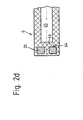
- the end face of the permanent magnet 20 does not necessarily have to cover the entire end face 34, but can also only, as FIG. 2b shows, restrict to the radially outer edge region of the piston 6.
- the end face 34 is a in the region of the central axis 31 of the cylindrical piston 6 to recognize central recess 35 by a centering pin of a mold originates, which the permanent magnet during injection molding of the support body 30 20 receives with its central recess 205, centered and in this position fixed while the plastic piston 6 is injected around it.
- On the side of the permanent magnet 20 facing away from the pressure chamber is over the entire cross-sectional area formed a partition 66, the Pressure chamber 12 and the permanent magnet 20 arranged therein against the Atmosphere seals.
- the permanent magnet 20 with a receiving device to detect the outer peripheral surface and the central recess 205 with plastic to eject, starting from the partition 66 an axial extension 67 is formed in the direction of the end face 34, which on the there End face of the permanent magnet 20 a radially outward, the Permanent magnet 20 thereby forms axially enclosing collar 68.
- the outer circumferential surface of the permanent magnet 20 is not extrusion-coated with plastic and the outer diameter of the permanent magnet 20 may be that of the Piston 6 correspond.
- the central recess of the permanent magnet 20 can also be stepped in diameter on the end face, so that the collar 68 inside the axial extent of the permanent magnet 20 are formed can and does not protrude beyond the permanent magnet 20, which is a special space-saving arrangement is created.
- the permanent magnet can slightly have a smaller outer diameter than the piston 6. The permanent magnet in this way remains in the immediate radial vicinity of the at least a sensor 24, 26 arranged on the housing 4 is positioned.
- the permanent magnet can be in a further alternative embodiment 20 fully embedded in the plastic and both against the pressure chamber 12 and be encapsulated against the atmosphere, so that a special surface treatment of the permanent magnet 20 is omitted can.
- This configuration has the advantage that even if the relatively brittle permanent magnet 20, whose shape and function are preserved remains and no functional impairment for the sensor system and the hydraulic system is to be expected.
- Figure 3a shows a piston 6 which, in contrast to the representations of the figures 2a-2d a piston shaft sleeve 32 made of a magnetisable or only weakly magnetizable Material, e.g. Stainless steel or aluminum, in which a support body 30 made of plastic, as already described here Cast part can be arranged.
- the support body 30 has the Face 345 facing pressure chamber 12 has a recess 36 into which the permanent magnet 20, which in turn is circular, but also disk-shaped or can be rod-shaped, is used.
- the permanent magnet 20 On the piston crown facing away from the end face is the permanent magnet 20 by means of several, from the support body 30 obliquely protruding spring tongues 38 and resiliently can thereby better absorb impulsive changes in movement of the piston 6, without being exposed to the risk of destruction.
- the piston 6 in the example encasing the piston shaft sleeve 32 has a bottom 325 on, which seals the permanent magnet 20 against the pressure chamber 12 and this against a slight bias of the spring tongues 38 in its assembly position guaranteed.
- FIG. 3b differs from the illustration in FIG. 3a only in that that the permanent magnet 20 instead of the spring tongues 38 on a compressible elastic flat base 40 is mounted.
- an elastic ring for example an O-ring, can also be used as a support.
- 3c shows a support body 30 of a piston 6, in which front area facing the piston crown, several radial spring tongues 44 and axial spring tongues 46 for the elastic mounting of the permanent magnet 20 are formed.
Landscapes
- Engineering & Computer Science (AREA)
- General Engineering & Computer Science (AREA)
- Mechanical Engineering (AREA)
- Physics & Mathematics (AREA)
- Fluid Mechanics (AREA)
- Hydraulic Clutches, Magnetic Clutches, Fluid Clutches, And Fluid Joints (AREA)
- Actuator (AREA)
- Measurement Of Length, Angles, Or The Like Using Electric Or Magnetic Means (AREA)
- Chair Legs, Seat Parts, And Backrests (AREA)
- External Artificial Organs (AREA)
- Braking Arrangements (AREA)
Applications Claiming Priority (2)
| Application Number | Priority Date | Filing Date | Title |
|---|---|---|---|
| DE10238402A DE10238402A1 (de) | 2002-08-22 | 2002-08-22 | Kolben-Zylindereinheit |
| DE10238402 | 2002-08-22 |
Publications (3)
| Publication Number | Publication Date |
|---|---|
| EP1391615A2 true EP1391615A2 (fr) | 2004-02-25 |
| EP1391615A3 EP1391615A3 (fr) | 2005-06-01 |
| EP1391615B1 EP1391615B1 (fr) | 2006-11-22 |
Family
ID=30775504
Family Applications (1)
| Application Number | Title | Priority Date | Filing Date |
|---|---|---|---|
| EP03018294A Expired - Lifetime EP1391615B1 (fr) | 2002-08-22 | 2003-08-12 | Unité de piston-cylindre |
Country Status (3)
| Country | Link |
|---|---|
| EP (1) | EP1391615B1 (fr) |
| AT (1) | ATE346245T1 (fr) |
| DE (2) | DE10238402A1 (fr) |
Cited By (14)
| Publication number | Priority date | Publication date | Assignee | Title |
|---|---|---|---|---|
| EP1602544A1 (fr) * | 2004-06-04 | 2005-12-07 | Zf Friedrichshafen Ag | Maítre-cylindre hydraulique |
| US7219495B2 (en) | 2004-06-04 | 2007-05-22 | Zf Friedrichshafen Ag | Hydraulic cylinder |
| EP1961985A3 (fr) * | 2007-02-23 | 2010-07-14 | LuK Lamellen und Kupplungsbau Beteiligungs KG | Cylindre récepteur doté d'un dispositif de mesure de trajectoire |
| WO2011124198A1 (fr) * | 2010-04-08 | 2011-10-13 | Schaeffler Technologies Gmbh & Co. Kg | Système de mesure de déplacement linéaire |
| WO2013037342A1 (fr) * | 2011-09-16 | 2013-03-21 | Schaeffler Technologies AG & Co. KG | Maître-cylindre ou cylindre récepteur et dispositif de mesure de course |
| WO2013160237A1 (fr) * | 2012-04-25 | 2013-10-31 | Avl List Gmbh | Ensemble piston-cylindre actionné par un fluide sous pression |
| WO2014079445A1 (fr) * | 2012-11-23 | 2014-05-30 | Schaeffler Technologies AG & Co. KG | Piston doté d'un élément de détection et ensemble piston-cylindre |
| EP2930376A1 (fr) * | 2014-04-11 | 2015-10-14 | Schaeffler Technologies GmbH & Co. KG | Vérin d'actionnement doté d'un système de détection |
| WO2015192845A1 (fr) * | 2014-06-16 | 2015-12-23 | Schaeffler Technologies AG & Co. KG | Logement de capteur pour cylindre hydraulique et procédé de fixation d'un capteur |
| CN105221599A (zh) * | 2014-06-20 | 2016-01-06 | 舍弗勒技术股份两合公司 | 离合器总泵、离合器分离系统 |
| CN110067818A (zh) * | 2018-01-23 | 2019-07-30 | 舍弗勒技术股份两合公司 | 具有多个单活塞的副缸,操纵装置以及离合器系统 |
| WO2019158158A1 (fr) * | 2018-02-15 | 2019-08-22 | Schaeffler Technologies AG & Co. KG | Maître-cylindre avec ressort partiellement disposé en-dehors du boîtier, dispositif d'actionnement et système d'embrayage |
| US11535497B2 (en) * | 2017-12-22 | 2022-12-27 | Schwing Gmbh | Hydraulic rotary drive |
| DE102015201643B4 (de) | 2015-01-30 | 2024-10-02 | Schaeffler Technologies AG & Co. KG | Hydraulikzylinder für ein Kupplungsbetätigungssystem oder Bremsbetätigungssystem mit einem Wegmesssystem |
Families Citing this family (4)
| Publication number | Priority date | Publication date | Assignee | Title |
|---|---|---|---|---|
| DE102004027117A1 (de) * | 2004-06-03 | 2005-12-22 | Zf Friedrichshafen Ag | Einrichtung zur Erfassung der Wegposition eines Kupplungskolbens zur Kupplungsbetätigung, der in einer rotierenden Kupplung angeordnet ist |
| DE102006032916A1 (de) * | 2006-07-15 | 2008-01-24 | Zf Friedrichshafen Ag | Einrichtung zur Erfassung der Wegposition eines Kupplungskolbens |
| DE102014211430A1 (de) * | 2014-06-16 | 2015-12-17 | Schaeffler Technologies AG & Co. KG | Geberzylinder für ein Kupplungsausrücksystem |
| DE102020216513A1 (de) | 2020-12-11 | 2022-06-15 | Continental Teves Ag & Co. Ohg | Hydraulisches Aggregat mit einer Erfassungsvorrichtung für Kolbenpositionserfassung |
Citations (4)
| Publication number | Priority date | Publication date | Assignee | Title |
|---|---|---|---|---|
| DE4116651A1 (de) | 1990-07-03 | 1992-01-09 | Festo Kg | Arbeitszylinder |
| DE69000218T2 (de) | 1989-09-05 | 1993-03-25 | Philippe Robert Louis Roudaut | Kolben-zylinder-einheit mit einer einrichtung zur bestimmung und bestaetigung der kolbenstellung. |
| DE4341810A1 (de) | 1993-12-08 | 1995-06-14 | Festo Kg | Sensoreinrichtung zur Positionserkennung eines Kolbens |
| DE19915832A1 (de) | 1999-04-08 | 2000-07-06 | Bayerische Motoren Werke Ag | Fahrzeug mit einem Stellungsgeber |
Family Cites Families (4)
| Publication number | Priority date | Publication date | Assignee | Title |
|---|---|---|---|---|
| DE3910691C2 (de) * | 1989-04-03 | 1998-07-09 | Teves Gmbh Alfred | Fluidaggregat |
| DE4320840C1 (de) * | 1993-06-23 | 1994-12-15 | Freudenberg Carl Fa | Dichtung für einen pneumatisch angetriebenen Kolben |
| DE19816513A1 (de) * | 1998-04-14 | 1999-10-21 | Mannesmann Sachs Ag | Betätigungselement für eine druckmittelbetätigte Kupplung |
| DE10049913A1 (de) * | 1999-10-18 | 2001-04-19 | Luk Lamellen & Kupplungsbau | Geberzylinder |
-
2002
- 2002-08-22 DE DE10238402A patent/DE10238402A1/de not_active Withdrawn
-
2003
- 2003-08-12 DE DE50305734T patent/DE50305734D1/de not_active Expired - Fee Related
- 2003-08-12 AT AT03018294T patent/ATE346245T1/de not_active IP Right Cessation
- 2003-08-12 EP EP03018294A patent/EP1391615B1/fr not_active Expired - Lifetime
Patent Citations (4)
| Publication number | Priority date | Publication date | Assignee | Title |
|---|---|---|---|---|
| DE69000218T2 (de) | 1989-09-05 | 1993-03-25 | Philippe Robert Louis Roudaut | Kolben-zylinder-einheit mit einer einrichtung zur bestimmung und bestaetigung der kolbenstellung. |
| DE4116651A1 (de) | 1990-07-03 | 1992-01-09 | Festo Kg | Arbeitszylinder |
| DE4341810A1 (de) | 1993-12-08 | 1995-06-14 | Festo Kg | Sensoreinrichtung zur Positionserkennung eines Kolbens |
| DE19915832A1 (de) | 1999-04-08 | 2000-07-06 | Bayerische Motoren Werke Ag | Fahrzeug mit einem Stellungsgeber |
Cited By (17)
| Publication number | Priority date | Publication date | Assignee | Title |
|---|---|---|---|---|
| US7219495B2 (en) | 2004-06-04 | 2007-05-22 | Zf Friedrichshafen Ag | Hydraulic cylinder |
| EP1602544A1 (fr) * | 2004-06-04 | 2005-12-07 | Zf Friedrichshafen Ag | Maítre-cylindre hydraulique |
| EP1961985A3 (fr) * | 2007-02-23 | 2010-07-14 | LuK Lamellen und Kupplungsbau Beteiligungs KG | Cylindre récepteur doté d'un dispositif de mesure de trajectoire |
| DE112011101226B4 (de) | 2010-04-08 | 2018-07-19 | Schaeffler Technologies AG & Co. KG | Linearwegmesssystem |
| WO2011124198A1 (fr) * | 2010-04-08 | 2011-10-13 | Schaeffler Technologies Gmbh & Co. Kg | Système de mesure de déplacement linéaire |
| WO2013037342A1 (fr) * | 2011-09-16 | 2013-03-21 | Schaeffler Technologies AG & Co. KG | Maître-cylindre ou cylindre récepteur et dispositif de mesure de course |
| WO2013160237A1 (fr) * | 2012-04-25 | 2013-10-31 | Avl List Gmbh | Ensemble piston-cylindre actionné par un fluide sous pression |
| WO2014079445A1 (fr) * | 2012-11-23 | 2014-05-30 | Schaeffler Technologies AG & Co. KG | Piston doté d'un élément de détection et ensemble piston-cylindre |
| EP2930376A1 (fr) * | 2014-04-11 | 2015-10-14 | Schaeffler Technologies GmbH & Co. KG | Vérin d'actionnement doté d'un système de détection |
| WO2015192845A1 (fr) * | 2014-06-16 | 2015-12-23 | Schaeffler Technologies AG & Co. KG | Logement de capteur pour cylindre hydraulique et procédé de fixation d'un capteur |
| CN106662172A (zh) * | 2014-06-16 | 2017-05-10 | 舍弗勒技术股份两合公司 | 用于液压缸的传感器接收件和用于固定传感器的方法 |
| CN106662172B (zh) * | 2014-06-16 | 2018-12-18 | 舍弗勒技术股份两合公司 | 用于液压缸的传感器接收件和用于固定传感器的方法 |
| CN105221599A (zh) * | 2014-06-20 | 2016-01-06 | 舍弗勒技术股份两合公司 | 离合器总泵、离合器分离系统 |
| DE102015201643B4 (de) | 2015-01-30 | 2024-10-02 | Schaeffler Technologies AG & Co. KG | Hydraulikzylinder für ein Kupplungsbetätigungssystem oder Bremsbetätigungssystem mit einem Wegmesssystem |
| US11535497B2 (en) * | 2017-12-22 | 2022-12-27 | Schwing Gmbh | Hydraulic rotary drive |
| CN110067818A (zh) * | 2018-01-23 | 2019-07-30 | 舍弗勒技术股份两合公司 | 具有多个单活塞的副缸,操纵装置以及离合器系统 |
| WO2019158158A1 (fr) * | 2018-02-15 | 2019-08-22 | Schaeffler Technologies AG & Co. KG | Maître-cylindre avec ressort partiellement disposé en-dehors du boîtier, dispositif d'actionnement et système d'embrayage |
Also Published As
| Publication number | Publication date |
|---|---|
| DE50305734D1 (de) | 2007-01-04 |
| EP1391615A3 (fr) | 2005-06-01 |
| DE10238402A1 (de) | 2004-03-04 |
| ATE346245T1 (de) | 2006-12-15 |
| EP1391615B1 (fr) | 2006-11-22 |
Similar Documents
| Publication | Publication Date | Title |
|---|---|---|
| EP1391615A2 (fr) | Unité de piston-cylindre | |
| EP2337716B1 (fr) | Électrovanne | |
| EP1489385B1 (fr) | Dispositif pour détecter la position axiale d'un premier corps se deplaçant relativement à un second corps | |
| DE20308810U1 (de) | Kolben-Zylinder-Aggregat mit einem Sensorsystem | |
| DE102015219375B4 (de) | Bremshauptzylinder | |
| EP1369597A2 (fr) | Vérin hydraulique | |
| DE102012212525A1 (de) | Hauptbremszylinder mit einer Vorrichtung zur berührungslosen Überwachung von Position und Bewegung eines linear bewegbaren Kolbens | |
| DE102009010132A1 (de) | Hydraulikzylinder mit Informationsgeber | |
| DE102010018773A1 (de) | Zentralausrücker | |
| EP3121495B2 (fr) | Vanne de commande electromagnetique | |
| DE10323797B4 (de) | Kolben-Zylinder-Aggregat mit einem Sensorsystem | |
| EP1602544A1 (fr) | Maítre-cylindre hydraulique | |
| DE102008057107A1 (de) | Wegmesssystem für ein Kupplungsausrücksystem | |
| DE102004014808A1 (de) | Vorrichtung zur Überwachung von Position und Bewegung eines Bremspedals | |
| DE68915345T2 (de) | Elektrischer Schalter für einen pneumatischen Bremsservomotor. | |
| EP1309803B1 (fr) | Entrainement lineaire | |
| DE102012022520A1 (de) | Hauptbremszylinderanordnung mit Betätigungserfassung für eine Kraftfahrzeugbremsanlage | |
| DE3918909A1 (de) | Hauptzylinder, insbesondere fuer eine blockiergeschuetzte, hydraulische bremsanlage, mit einer einrichtung zur bestimmung der lage des hauptkolbens | |
| DE102010002325A1 (de) | Elektrisches Schaltelement | |
| DE102018001756A1 (de) | Zentralausrücker für eine pneumatische Kupplungsbetätigung | |
| EP3527760B1 (fr) | Boulon d'arrêt | |
| DE102012223736A1 (de) | Kolben-Zylinder-Anordnung, insbesondere zur Verwendung in einem Kupplungsbetätigungssystem in einem Kraftfahrzeug | |
| DE102009011807A1 (de) | Wegmesssystem für einen Geberzylinder | |
| DE102006050525A1 (de) | Wegmesssystem für Kupplungsausrücksysteme | |
| EP4194720B1 (fr) | Unité de verrouillage |
Legal Events
| Date | Code | Title | Description |
|---|---|---|---|
| PUAI | Public reference made under article 153(3) epc to a published international application that has entered the european phase |
Free format text: ORIGINAL CODE: 0009012 |
|
| AK | Designated contracting states |
Kind code of ref document: A2 Designated state(s): AT BE BG CH CY CZ DE DK EE ES FI FR GB GR HU IE IT LI LU MC NL PT RO SE SI SK TR |
|
| AX | Request for extension of the european patent |
Extension state: AL LT LV MK |
|
| PUAL | Search report despatched |
Free format text: ORIGINAL CODE: 0009013 |
|
| AK | Designated contracting states |
Kind code of ref document: A3 Designated state(s): AT BE BG CH CY CZ DE DK EE ES FI FR GB GR HU IE IT LI LU MC NL PT RO SE SI SK TR |
|
| AX | Request for extension of the european patent |
Extension state: AL LT LV MK |
|
| 17P | Request for examination filed |
Effective date: 20050617 |
|
| AKX | Designation fees paid |
Designated state(s): AT BE BG CH CY CZ DE DK EE ES FI FR GB GR HU IE IT LI LU MC NL PT RO SE SI SK TR |
|
| GRAP | Despatch of communication of intention to grant a patent |
Free format text: ORIGINAL CODE: EPIDOSNIGR1 |
|
| GRAS | Grant fee paid |
Free format text: ORIGINAL CODE: EPIDOSNIGR3 |
|
| GRAA | (expected) grant |
Free format text: ORIGINAL CODE: 0009210 |
|
| AK | Designated contracting states |
Kind code of ref document: B1 Designated state(s): AT BE BG CH CY CZ DE DK EE ES FI FR GB GR HU IE IT LI LU MC NL PT RO SE SI SK TR |
|
| PG25 | Lapsed in a contracting state [announced via postgrant information from national office to epo] |
Ref country code: IT Free format text: LAPSE BECAUSE OF FAILURE TO SUBMIT A TRANSLATION OF THE DESCRIPTION OR TO PAY THE FEE WITHIN THE PRESCRIBED TIME-LIMIT;WARNING: LAPSES OF ITALIAN PATENTS WITH EFFECTIVE DATE BEFORE 2007 MAY HAVE OCCURRED AT ANY TIME BEFORE 2007. THE CORRECT EFFECTIVE DATE MAY BE DIFFERENT FROM THE ONE RECORDED. Effective date: 20061122 Ref country code: SI Free format text: LAPSE BECAUSE OF FAILURE TO SUBMIT A TRANSLATION OF THE DESCRIPTION OR TO PAY THE FEE WITHIN THE PRESCRIBED TIME-LIMIT Effective date: 20061122 Ref country code: IE Free format text: LAPSE BECAUSE OF FAILURE TO SUBMIT A TRANSLATION OF THE DESCRIPTION OR TO PAY THE FEE WITHIN THE PRESCRIBED TIME-LIMIT Effective date: 20061122 Ref country code: CZ Free format text: LAPSE BECAUSE OF FAILURE TO SUBMIT A TRANSLATION OF THE DESCRIPTION OR TO PAY THE FEE WITHIN THE PRESCRIBED TIME-LIMIT Effective date: 20061122 Ref country code: SK Free format text: LAPSE BECAUSE OF FAILURE TO SUBMIT A TRANSLATION OF THE DESCRIPTION OR TO PAY THE FEE WITHIN THE PRESCRIBED TIME-LIMIT Effective date: 20061122 Ref country code: NL Free format text: LAPSE BECAUSE OF FAILURE TO SUBMIT A TRANSLATION OF THE DESCRIPTION OR TO PAY THE FEE WITHIN THE PRESCRIBED TIME-LIMIT Effective date: 20061122 Ref country code: RO Free format text: LAPSE BECAUSE OF FAILURE TO SUBMIT A TRANSLATION OF THE DESCRIPTION OR TO PAY THE FEE WITHIN THE PRESCRIBED TIME-LIMIT Effective date: 20061122 Ref country code: FI Free format text: LAPSE BECAUSE OF FAILURE TO SUBMIT A TRANSLATION OF THE DESCRIPTION OR TO PAY THE FEE WITHIN THE PRESCRIBED TIME-LIMIT Effective date: 20061122 |
|
| REG | Reference to a national code |
Ref country code: GB Ref legal event code: FG4D Free format text: NOT ENGLISH |
|
| REG | Reference to a national code |
Ref country code: CH Ref legal event code: EP |
|
| REG | Reference to a national code |
Ref country code: IE Ref legal event code: FG4D Free format text: LANGUAGE OF EP DOCUMENT: GERMAN |
|
| REF | Corresponds to: |
Ref document number: 50305734 Country of ref document: DE Date of ref document: 20070104 Kind code of ref document: P |
|
| PG25 | Lapsed in a contracting state [announced via postgrant information from national office to epo] |
Ref country code: BG Free format text: LAPSE BECAUSE OF FAILURE TO SUBMIT A TRANSLATION OF THE DESCRIPTION OR TO PAY THE FEE WITHIN THE PRESCRIBED TIME-LIMIT Effective date: 20070222 Ref country code: SE Free format text: LAPSE BECAUSE OF FAILURE TO SUBMIT A TRANSLATION OF THE DESCRIPTION OR TO PAY THE FEE WITHIN THE PRESCRIBED TIME-LIMIT Effective date: 20070222 Ref country code: DK Free format text: LAPSE BECAUSE OF FAILURE TO SUBMIT A TRANSLATION OF THE DESCRIPTION OR TO PAY THE FEE WITHIN THE PRESCRIBED TIME-LIMIT Effective date: 20070222 |
|
| PG25 | Lapsed in a contracting state [announced via postgrant information from national office to epo] |
Ref country code: ES Free format text: LAPSE BECAUSE OF FAILURE TO SUBMIT A TRANSLATION OF THE DESCRIPTION OR TO PAY THE FEE WITHIN THE PRESCRIBED TIME-LIMIT Effective date: 20070305 |
|
| PG25 | Lapsed in a contracting state [announced via postgrant information from national office to epo] |
Ref country code: PT Free format text: LAPSE BECAUSE OF FAILURE TO SUBMIT A TRANSLATION OF THE DESCRIPTION OR TO PAY THE FEE WITHIN THE PRESCRIBED TIME-LIMIT Effective date: 20070423 |
|
| ET | Fr: translation filed | ||
| NLV1 | Nl: lapsed or annulled due to failure to fulfill the requirements of art. 29p and 29m of the patents act | ||
| GBV | Gb: ep patent (uk) treated as always having been void in accordance with gb section 77(7)/1977 [no translation filed] |
Effective date: 20061122 |
|
| REG | Reference to a national code |
Ref country code: IE Ref legal event code: FD4D |
|
| PLBE | No opposition filed within time limit |
Free format text: ORIGINAL CODE: 0009261 |
|
| STAA | Information on the status of an ep patent application or granted ep patent |
Free format text: STATUS: NO OPPOSITION FILED WITHIN TIME LIMIT |
|
| 26N | No opposition filed |
Effective date: 20070823 |
|
| PG25 | Lapsed in a contracting state [announced via postgrant information from national office to epo] |
Ref country code: GB Free format text: LAPSE BECAUSE OF FAILURE TO SUBMIT A TRANSLATION OF THE DESCRIPTION OR TO PAY THE FEE WITHIN THE PRESCRIBED TIME-LIMIT Effective date: 20061122 |
|
| BERE | Be: lapsed |
Owner name: ZF SACHS A.G. Effective date: 20070831 |
|
| REG | Reference to a national code |
Ref country code: CH Ref legal event code: PL |
|
| PG25 | Lapsed in a contracting state [announced via postgrant information from national office to epo] |
Ref country code: LI Free format text: LAPSE BECAUSE OF NON-PAYMENT OF DUE FEES Effective date: 20070831 Ref country code: CH Free format text: LAPSE BECAUSE OF NON-PAYMENT OF DUE FEES Effective date: 20070831 Ref country code: MC Free format text: LAPSE BECAUSE OF NON-PAYMENT OF DUE FEES Effective date: 20070831 Ref country code: GR Free format text: LAPSE BECAUSE OF FAILURE TO SUBMIT A TRANSLATION OF THE DESCRIPTION OR TO PAY THE FEE WITHIN THE PRESCRIBED TIME-LIMIT Effective date: 20070223 |
|
| PG25 | Lapsed in a contracting state [announced via postgrant information from national office to epo] |
Ref country code: BE Free format text: LAPSE BECAUSE OF NON-PAYMENT OF DUE FEES Effective date: 20070831 |
|
| PGFP | Annual fee paid to national office [announced via postgrant information from national office to epo] |
Ref country code: DE Payment date: 20080829 Year of fee payment: 6 |
|
| PG25 | Lapsed in a contracting state [announced via postgrant information from national office to epo] |
Ref country code: AT Free format text: LAPSE BECAUSE OF NON-PAYMENT OF DUE FEES Effective date: 20070812 |
|
| PG25 | Lapsed in a contracting state [announced via postgrant information from national office to epo] |
Ref country code: EE Free format text: LAPSE BECAUSE OF FAILURE TO SUBMIT A TRANSLATION OF THE DESCRIPTION OR TO PAY THE FEE WITHIN THE PRESCRIBED TIME-LIMIT Effective date: 20061122 |
|
| PG25 | Lapsed in a contracting state [announced via postgrant information from national office to epo] |
Ref country code: CY Free format text: LAPSE BECAUSE OF FAILURE TO SUBMIT A TRANSLATION OF THE DESCRIPTION OR TO PAY THE FEE WITHIN THE PRESCRIBED TIME-LIMIT Effective date: 20061122 Ref country code: LU Free format text: LAPSE BECAUSE OF NON-PAYMENT OF DUE FEES Effective date: 20070812 |
|
| PG25 | Lapsed in a contracting state [announced via postgrant information from national office to epo] |
Ref country code: HU Free format text: LAPSE BECAUSE OF FAILURE TO SUBMIT A TRANSLATION OF THE DESCRIPTION OR TO PAY THE FEE WITHIN THE PRESCRIBED TIME-LIMIT Effective date: 20070523 Ref country code: TR Free format text: LAPSE BECAUSE OF FAILURE TO SUBMIT A TRANSLATION OF THE DESCRIPTION OR TO PAY THE FEE WITHIN THE PRESCRIBED TIME-LIMIT Effective date: 20061122 |
|
| PG25 | Lapsed in a contracting state [announced via postgrant information from national office to epo] |
Ref country code: DE Free format text: LAPSE BECAUSE OF NON-PAYMENT OF DUE FEES Effective date: 20100302 |
|
| PGFP | Annual fee paid to national office [announced via postgrant information from national office to epo] |
Ref country code: FR Payment date: 20120823 Year of fee payment: 10 |
|
| REG | Reference to a national code |
Ref country code: FR Ref legal event code: ST Effective date: 20140430 |
|
| PG25 | Lapsed in a contracting state [announced via postgrant information from national office to epo] |
Ref country code: FR Free format text: LAPSE BECAUSE OF NON-PAYMENT OF DUE FEES Effective date: 20130902 |