EP2930376A1 - Vérin d'actionnement doté d'un système de détection - Google Patents
Vérin d'actionnement doté d'un système de détection Download PDFInfo
- Publication number
- EP2930376A1 EP2930376A1 EP15163081.1A EP15163081A EP2930376A1 EP 2930376 A1 EP2930376 A1 EP 2930376A1 EP 15163081 A EP15163081 A EP 15163081A EP 2930376 A1 EP2930376 A1 EP 2930376A1
- Authority
- EP
- European Patent Office
- Prior art keywords
- receptacle
- piston
- lid
- cover
- actuating cylinder
- Prior art date
- Legal status (The legal status is an assumption and is not a legal conclusion. Google has not performed a legal analysis and makes no representation as to the accuracy of the status listed.)
- Pending
Links
Images


Classifications
-
- F—MECHANICAL ENGINEERING; LIGHTING; HEATING; WEAPONS; BLASTING
- F15—FLUID-PRESSURE ACTUATORS; HYDRAULICS OR PNEUMATICS IN GENERAL
- F15B—SYSTEMS ACTING BY MEANS OF FLUIDS IN GENERAL; FLUID-PRESSURE ACTUATORS, e.g. SERVOMOTORS; DETAILS OF FLUID-PRESSURE SYSTEMS, NOT OTHERWISE PROVIDED FOR
- F15B15/00—Fluid-actuated devices for displacing a member from one position to another; Gearing associated therewith
- F15B15/20—Other details, e.g. assembly with regulating devices
- F15B15/28—Means for indicating the position, e.g. end of stroke
- F15B15/2892—Means for indicating the position, e.g. end of stroke characterised by the attachment means
Definitions
- the invention relates to an actuating cylinder with a sensor arrangement, in particular a master cylinder with sensor arrangement for a pressure medium actuation, for example a clutch of a motor vehicle.
- Master cylinder actuating cylinders in actuators are used in motor vehicles, in particular for the operation of aggregates, in particular for the actuation of clutches, wherein the initial actuation of the piston of the piston cylinder unit of the master cylinder can be done automatically controlled, for example by means of a pedal manually or by means of an actuator.
- Magnetic sensor devices which have a magnetic element connected to the piston displaceable in the cylinder space are used in the prior art, a sensor element being arranged outside the cylinder space, which allows a conclusion to be drawn about the position of the piston from the measured magnetic field.
- Such sensor elements are very sensitive to external disturbances and environmental influences, which is why they are well protected to be arranged on the housing of the master cylinder.
- These sensor elements must also be fixedly connected to the housing so that movement of the sensor element is not erroneously interpreted as a displacement of the piston.
- such sensor elements are formed as a self-contained housing with molded connector, which are connected to the housing of the master cylinder by means of rivets.
- The requires a high production cost and installation costs.
- An embodiment of the invention relates to an actuating cylinder with a sensor arrangement, comprising a piston-cylinder unit with a housing in which a cylinder chamber with a displaceably arranged therein piston, wherein on the cylinder chamber, a fluid connection is provided and the piston connected to a piston rod for actuating the piston is, with the piston, a donor element is arranged, wherein outside of the cylinder chamber, a sensor element is arranged to determine the position of the donor element, wherein on the housing a receptacle is provided, in which a sealed lid-like element is closed, wherein the sensor element with is connected to the lid-like element and is mounted on the receiving side facing the lid-like element and can be placed in the receptacle, wherein on the side facing away from the receptacle of the lid-like element, a plug element is provided for contacting the sensor elements.
- the actuating cylinder may preferably be a master cylinder or a slave cylinder, which is used in a pressure medium section of a pressure medium actuating device, such as hydraulic or pneumatic device. Due to the construction that a receptacle is provided on the housing, into which a cover-like element can be closed sealed, wherein the sensor element is connected to the lid-like element and is fixed on the receiving side facing the lid-like element and placed in the receptacle is, wherein on the side facing away from the receptacle of the lid-like element, a plug element is provided for contacting the sensor element, the sensor element can be easily connected to the housing of the actuating cylinder, the position of the sensor element is securely defined and fixed and it can in a simple manner an attachment and sealing of the installation space of the sensor element take place.
- a receptacle is provided on the housing, into which a cover-like element can be closed sealed, wherein the sensor element is connected to the lid-like element and is fixed on the receiving side facing the lid
- the sensor element is positively and / or materially connected to the cover-like element.
- a simple assembly can take place when the sensor element is attached to a substantially planar part of the lid-like element by positive connection, for example by means of locking means and / or by material connection, for example by gluing.
- the sensor element has connection contacts which are electrically connected to contacts of the plug element.
- the sensor element can be electrically connected to electrical contacts of the plug element, wherein the contacts preferably pass through a wall of the plug member and so the interior of the receptacle is sealed in the region of the contacts.
- the receptacle prefferably has a circumferential wall on which the cover-like element bears in a sealing manner.
- a substantially planar contact surface can be formed which is to be sealed by means of a sealing element, such as an O-ring.
- the cover-like element has an at least substantially circumferential wall which bears against the peripheral wall of the receptacle. As a result, a secure seal and / or attachment can be achieved.
- peripheral wall of the cover-like element has recesses distributed on the circumference of the wall.
- a positional orientation can be determined if projections are provided on the housing, which engage in the recesses. This ensures that the lid-like element is not arbitrarily orientable relative to the housing.
- peripheral wall of the receptacle and / or the circumferential wall of the cover-like element has a receptacle for a seal in which a circumferential seal is received in order to seal the receptacle against the cover-like element.
- locking means are provided on the peripheral wall of the receptacle and / or on the peripheral wall of the lid-like element, which cooperate with each other and positively connect the lid-like element with the receptacle.
- the latching means each have serrated projections and recesses which cooperate with each other.
- These prong-like projections and recesses may have the contour of saw teeth or fir trees, which run when pressing the lid-like element into the receptacle past each other and lock in such a way.
- the plug element protrudes from the lid-like element, wherein the plug element protrudes in the normal direction or at an angle to the normal direction of the lid-like element.
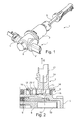
- FIG. 1 shows a schematic representation of an actuating cylinder 1 with a sensor assembly 2.
- the FIG. 2 shows a detail of it on average.
- the actuating cylinder 1 has in the interior a piston-cylinder unit, which is formed in a housing 3.
- the housing 3 is preferably formed at least in two parts in order to place the piston 8 in the cylinder chamber 9 of the piston-cylinder unit.
- a displaceably arranged therein piston 8 is provided in the cylinder chamber 9 .
- a fluid connection 4 is provided on the cylinder chamber 9 and thus also on the housing 3, in order to discharge a fluid from the cylinder chamber 9 or to introduce a fluid into the cylinder chamber 9.
- the piston is further connected to a piston rod 5 in order to operate the piston 8, for example, pedal-operated or by means of an actuator can.
- the piston rod 5 projects accordingly out of an opening of the housing 3.
- a transmitter element 10 is preferably arranged connected to the piston 8, wherein outside of the cylinder chamber 9, a sensor element 11 is arranged, which serves to determine the position of the encoder element 10.
- the transmitter element 10 may preferably be a magnetic element and / or an electrically conductive element, which is detectable from outside the housing 3 without contact, since the transmitter element 10 is arranged in the housing 3 and the sensor element 11 is placed outside the housing 3.
- a receptacle 6 is provided on the housing 3, which is sealed by a lid-like element 7, wherein the sensor element 11 is connected to the cover-like element 7.
- the sensor element can be positively and / or materially connected to the lid-like element, such as latched and / or glued.
- the sensor element 11 is mounted on the receptacle 6 facing side of the lid-like element 7 and placed in the receptacle 6.
- a plug element 12 is furthermore provided, which serves to make contact with the sensor element 11.
- electrical connection contacts 13 are provided on which the sensor element 11, which are electrically connected to contacts 14 of the plug element 12. The contacting can be done by plugging, soldering and / or welding.
- the receptacle 6 has a circumferential wall 15, on which the lid-like element 7 applies a sealing.
- a circumferential receptacle 16 is formed, which is configured U-shaped and which receives a sealing ring 17.
- the sealing ring 17 abuts against a sealing flange 18 of the lid-like element 7 and seals the interior 19 of the receptacle 6, see also FIG. 7 ,
- the lid-like element 7 has an at least substantially circumferential wall 20 which rests against the peripheral wall 15 of the receptacle 6.
- the wall 20 is disposed radially inside the wall 15.
- the lid-like element 7 in the wall 20 recesses 21, which are preferably distributed on the circumference of the wall 20. It is in FIG. 9 to recognize that two such recesses 21 are provided, which are not opposite, but have an angle of less than 180 ° to each other. This causes the lid-like element 7 can be used only in a fixed orientation in the receptacle 6.
- the receptacle 6 has to match appropriately oriented ribs 22 which engage in the recesses 21 when the lid-like element 7 engages in the receptacle 6 or covers, see FIG. 8 ,
- latching means 23, 24 are provided which cooperate with each other.
- the latching means 23, 24 are each designed as serrated projections and recesses which cooperate with each other. Leg insertion, the serrated projections slide past each other and then get caught.
- FIG. 2 shows that the plug member 12 protrudes from the lid-like element 7, wherein the plug member 12 protrudes in the normal direction 25.
- FIG. 5 another embodiment is shown in which the plug member 12 is inclined at an angle ⁇ to the normal direction. In the case of the example of FIG. 5 the angle is about 30 °, other angles of about 45 °, 60 ° or other angles are possible, depending on space conditions.
- the FIG. 4 shows an actuating cylinder 30 with a lid-like element 7 with angled plug element 12. The example of FIG. 4 is otherwise essentially the Example of FIG. 1 equal.
- the FIG. 3 also shows an alternative embodiment actuating cylinder 40, in which the wall 41 of the receptacle 6 is not formed in a horizontal section around, but square. Also, the lid-like element 42 is formed correspondingly angular, from which the plug member 12 protrudes.
- FIG. 6 shows the lid-like element 7 with a round planar element 26 from which protrudes the male member 12, wherein the wall 20 is mounted on the opposite side, but this is not recognizable. Also, the contacts 14 can be seen in the plug element. These are arranged in two rows in this embodiment. They can also be arranged elsewhere.
Landscapes
- Engineering & Computer Science (AREA)
- Physics & Mathematics (AREA)
- Fluid Mechanics (AREA)
- Mechanical Engineering (AREA)
- General Engineering & Computer Science (AREA)
- Measurement Of Length, Angles, Or The Like Using Electric Or Magnetic Means (AREA)
- Actuator (AREA)
Applications Claiming Priority (1)
| Application Number | Priority Date | Filing Date | Title |
|---|---|---|---|
| DE102014207030 | 2014-04-11 |
Publications (1)
| Publication Number | Publication Date |
|---|---|
| EP2930376A1 true EP2930376A1 (fr) | 2015-10-14 |
Family
ID=53181047
Family Applications (1)
| Application Number | Title | Priority Date | Filing Date |
|---|---|---|---|
| EP15163081.1A Pending EP2930376A1 (fr) | 2014-04-11 | 2015-04-10 | Vérin d'actionnement doté d'un système de détection |
Country Status (2)
| Country | Link |
|---|---|
| EP (1) | EP2930376A1 (fr) |
| DE (1) | DE102015206386A1 (fr) |
Citations (5)
| Publication number | Priority date | Publication date | Assignee | Title |
|---|---|---|---|---|
| DE20116818U1 (de) * | 2001-10-16 | 2002-01-17 | FTE automotive GmbH, 96106 Ebern | Hydraulikzylinder |
| EP1391615A2 (fr) * | 2002-08-22 | 2004-02-25 | ZF Sachs AG | Unité de piston-cylindre |
| US20050000772A1 (en) * | 2003-06-11 | 2005-01-06 | Steffen Wohner | Device for sensing the axial position, in relation to the other component, of one of two components mobile relative to each other |
| DE102006021129B3 (de) * | 2006-05-04 | 2007-06-28 | Smk Systeme Metall Kunststoff Gmbh & Co. Kg. | Ladedruckregler für Abgas-Turbolader von Brennkraftmotoren für Automobile |
| DE102010006058A1 (de) * | 2009-02-12 | 2010-08-19 | Luk Lamellen Und Kupplungsbau Beteiligungs Kg | Hydraulisches Kupplungs- oder Bremsbetätigungssystem |
-
2015
- 2015-04-10 EP EP15163081.1A patent/EP2930376A1/fr active Pending
- 2015-04-10 DE DE102015206386.0A patent/DE102015206386A1/de not_active Withdrawn
Patent Citations (5)
| Publication number | Priority date | Publication date | Assignee | Title |
|---|---|---|---|---|
| DE20116818U1 (de) * | 2001-10-16 | 2002-01-17 | FTE automotive GmbH, 96106 Ebern | Hydraulikzylinder |
| EP1391615A2 (fr) * | 2002-08-22 | 2004-02-25 | ZF Sachs AG | Unité de piston-cylindre |
| US20050000772A1 (en) * | 2003-06-11 | 2005-01-06 | Steffen Wohner | Device for sensing the axial position, in relation to the other component, of one of two components mobile relative to each other |
| DE102006021129B3 (de) * | 2006-05-04 | 2007-06-28 | Smk Systeme Metall Kunststoff Gmbh & Co. Kg. | Ladedruckregler für Abgas-Turbolader von Brennkraftmotoren für Automobile |
| DE102010006058A1 (de) * | 2009-02-12 | 2010-08-19 | Luk Lamellen Und Kupplungsbau Beteiligungs Kg | Hydraulisches Kupplungs- oder Bremsbetätigungssystem |
Also Published As
| Publication number | Publication date |
|---|---|
| DE102015206386A1 (de) | 2015-10-15 |
Similar Documents
| Publication | Publication Date | Title |
|---|---|---|
| EP2473767B1 (fr) | Soupape de vidange d'eau dotée d'une membrane-écran | |
| DE112007003725T5 (de) | Leitungsverbindungssystem für ein Druckfluidsystem | |
| DE102014225861A1 (de) | Sensoreinrichtung, insbesondere für die Verwendung in einem Kraftfahrzeug | |
| DE102013101120A1 (de) | Kabelfixierung | |
| EP3772595B1 (fr) | Unité de capteur pour cylindre fluidique et cylindre fluidique | |
| DE102007008862A1 (de) | Unfallsensor | |
| DE29811706U1 (de) | Vorrichtung zum Überwachen der Schließstellung eines Tankdeckels | |
| DE102015201367A1 (de) | Verbindungsvorrichtung | |
| EP3559429B1 (fr) | Soupape | |
| EP3468817B1 (fr) | Système de contrôle de la pression des pneus et procédé de montage d'un système de contrôle de la pression des pneus sur une jante | |
| DE102012022520A1 (de) | Hauptbremszylinderanordnung mit Betätigungserfassung für eine Kraftfahrzeugbremsanlage | |
| WO2017032794A1 (fr) | Entraînement actionné par un agent comprimé pour vanne de commande comportant un ensemble de capteurs | |
| DE102015206386A1 (de) | Betätigungszylinder mit Sensoranordnung | |
| DE102010031719A1 (de) | Vorrichtung zur Erfassung physikalischer Zustandsgrößen eines Mediums | |
| EP2264329A1 (fr) | Vérin à fluide sous pression pour un dispositif d'actionnement d'un véhicule automobile doté d'un piston pouvant être bloqué | |
| DE102015215963A1 (de) | Betätigungszylinder mit Sensoranordnung | |
| DE10039609A1 (de) | Drucksensor | |
| DE102012025518A1 (de) | Drucksensorelement | |
| DE102015204760A1 (de) | Betätigungszylinder mit Sensoranordnung | |
| DE202010011858U1 (de) | Stecker, inbesondere Photovoltaikstecker | |
| WO2015131895A1 (fr) | Système de débrayage pour un dispositif de commande d'embrayage | |
| DE102016113708A1 (de) | Steckverbindung | |
| DE202009014844U1 (de) | Leitungselement für eine im Erdreich zu verlegende Leitung | |
| DE102016013790A1 (de) | Elektrischer Schalter | |
| DE102012212046A1 (de) | Haltevorrichtung für Kolbenstange |
Legal Events
| Date | Code | Title | Description |
|---|---|---|---|
| PUAI | Public reference made under article 153(3) epc to a published international application that has entered the european phase |
Free format text: ORIGINAL CODE: 0009012 |
|
| AK | Designated contracting states |
Kind code of ref document: A1 Designated state(s): AL AT BE BG CH CY CZ DE DK EE ES FI FR GB GR HR HU IE IS IT LI LT LU LV MC MK MT NL NO PL PT RO RS SE SI SK SM TR |
|
| AX | Request for extension of the european patent |
Extension state: BA ME |
|
| 18W | Application withdrawn |
Effective date: 20160324 |
|
| D18W | Application withdrawn (deleted) | ||
| STAA | Information on the status of an ep patent application or granted ep patent |
Free format text: STATUS: THE APPLICATION IS DEEMED TO BE WITHDRAWN |
|
| 18D | Application deemed to be withdrawn |
Effective date: 20160415 |
|
| P01 | Opt-out of the competence of the unified patent court (upc) registered |
Effective date: 20230523 |