EP1391636B1 - Système de transmission de puissance pour vehicule - Google Patents
Système de transmission de puissance pour vehicule Download PDFInfo
- Publication number
- EP1391636B1 EP1391636B1 EP03018456A EP03018456A EP1391636B1 EP 1391636 B1 EP1391636 B1 EP 1391636B1 EP 03018456 A EP03018456 A EP 03018456A EP 03018456 A EP03018456 A EP 03018456A EP 1391636 B1 EP1391636 B1 EP 1391636B1
- Authority
- EP
- European Patent Office
- Prior art keywords
- gear
- continuously variable
- path
- vehicle
- backward travel
- Prior art date
- Legal status (The legal status is an assumption and is not a legal conclusion. Google has not performed a legal analysis and makes no representation as to the accuracy of the status listed.)
- Expired - Lifetime
Links
- 230000005540 biological transmission Effects 0.000 title claims description 41
- 230000007246 mechanism Effects 0.000 claims description 49
- 230000009467 reduction Effects 0.000 claims description 29
- 239000002184 metal Substances 0.000 description 5
- 230000008859 change Effects 0.000 description 3
- 230000002093 peripheral effect Effects 0.000 description 3
- 230000006872 improvement Effects 0.000 description 2
- 230000006866 deterioration Effects 0.000 description 1
- 238000010586 diagram Methods 0.000 description 1
- 238000000034 method Methods 0.000 description 1
- 238000012986 modification Methods 0.000 description 1
- 230000004048 modification Effects 0.000 description 1
- 230000008569 process Effects 0.000 description 1
- 238000011144 upstream manufacturing Methods 0.000 description 1
Images





Classifications
-
- F—MECHANICAL ENGINEERING; LIGHTING; HEATING; WEAPONS; BLASTING
- F16—ENGINEERING ELEMENTS AND UNITS; GENERAL MEASURES FOR PRODUCING AND MAINTAINING EFFECTIVE FUNCTIONING OF MACHINES OR INSTALLATIONS; THERMAL INSULATION IN GENERAL
- F16H—GEARING
- F16H37/00—Combinations of mechanical gearings, not provided for in groups F16H1/00 - F16H35/00
- F16H37/02—Combinations of mechanical gearings, not provided for in groups F16H1/00 - F16H35/00 comprising essentially only toothed or friction gearings
- F16H37/021—Combinations of mechanical gearings, not provided for in groups F16H1/00 - F16H35/00 comprising essentially only toothed or friction gearings toothed gearing combined with continuously variable friction gearing
- F16H37/022—Combinations of mechanical gearings, not provided for in groups F16H1/00 - F16H35/00 comprising essentially only toothed or friction gearings toothed gearing combined with continuously variable friction gearing the toothed gearing having orbital motion
Definitions
- the present invention relates to a power transmission system in a vehicle, comprising a continuously variable gear path and a multi-stage gear path provided in parallel for transmitting a driving force from an engine to driven wheels, according to the preamble of claim 1.
- a conventional power transmission system in a vehicle is known from Japanese Patent Publication No. 63-14228 .
- the rotation of a main shaft connected to an engine through a torque converter is transmitted to a counter shaft through a reduction gear train or a belt-type continuously variable transmission, and a forward/backward travel switching mechanism using a single-pinion type planetary gear mechanism is disposed between the counter shaft and driven wheels.
- a reduction gear train having a large reduction ratio is used; and during subsequent traveling of the vehicle, the reduction gear train is switched over to the belt-type continuously variable transmission to conduct the continuously variable gear shifting.
- the forward/backward travel switching mechanism for switching the forward and backward travels from one to another includes a forward clutch adapted to couple a carrier to an output shaft, and a reverse brake adapted to couple the carrier to a casing.
- the conventional power transmission system is designed as follows: when the forward clutch is brought into an engaged state, the carrier is coupled to the output shaft, whereby the rotation of the input shaft (the counter shaft) is transmitted, at the same speed and in the same rotational direction, to the output shaft to establish a forward gear shift stage; and when the reverse brake is brought into the engaged state, the rotation of the input shaft (the counter shaft) is transmitted, at an increased speed and in the reverse rotational direction, to the output shaft to establish a backward gear shift stage.
- a gear ratio between the input shaft and the output shaft can be set at 1:1, but resulting in several problems.
- the double-pinion type planetary gear mechanism having a large number of parts complicates the structure, and also the number of meshed portions of each gear is large and the rotational speed of the planetary gear is high resulting in an increase in noise.
- the present invention has been accomplished with such circumstance in view, and it is an object to provide a power transmission system in a vehicle including a continously variable gear path and a multi-stage gear path, in which a difference between gear ratios at the start of the forward travel and at the start of the backward travel is minimized.
- a power transmission system in a vehicle comprising a continuously variable gear path and a multi-stage gear path provided in parallel for transmitting a driving force from an engine to the driven wheels
- the continuously variable gear path includes a continuously variable gear mechanism and a single-pinion type forward/backward travel switching mechanism adapted to receive the driving force input from the engine through a sun gear, characterized in that the forward/backward travel switching mechanism is adapted to output the driving force to the continuously variable gear mechanism through a ring gear
- the multi-stage gear path is set at a reduction ratio closer to a LOW side than that of the continuously variable gear mechanism in the lowest-speed state thereof.
- forward/backward travel switching is disposed in the continously variable gear path, and the multi-stage gear path is set at a reduction gear ratio closer to the LOW side than that of the continously variable gear mechanism. Therefore, a difference between the gear ratios in the multi-stage gear path and the continously variable gear path can be minimized while using the single-pinion type forward/backward travel switching mechanism which is simple in structure and generates less noise, by using the multi-stage gear path having the reduction gear ratio closer to the LOW side that that of the continously variable gear path which includes the forward/backward travel switching mechanism and the continously variable gear mechanism each having a speed reducing function at the start of backward travel of the vehicle.
- the forward traveling and the backward traveling are switched over from one to another, it is unnecessary to suddenly change the gear ratio of the continously variable gear mechanism, which can contribute to an improvement in durability of the continuously variable gear mechanism.
- the forward/backward travel switching mechanism is of a single-pinion type adapted to receive the driving force input from the engine through a sun gear and to output the driving force to the continuously variable gear mechanism through a ring gear.
- the gear ratio in the multi-stage gear path and the gear ratio in the continuously variable gear path when the continuously variable gear mechanism is in a lowest speed state during backward travel are set at substantially the same value.
- the gear ratio in the multi-stage gear path used at the start of the forward travel and the gear ratio in the continuously variable gear path used at the start of the backward travel can be set at substantially the same value, and hence driven wheels can be driven with the same torque at the start of the forward travel and at the start of the backward travel of the vehicle.
- a belt-type continuously variable transmission 29 in an embodiment corresponds to the continuously variable gear-shifting mechanism of the present invention.
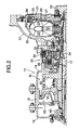
- a casing 11 of a continuously variable transmission M for a vehicle comprises a torque converter case 12, a central transmission case 14, a left transmission case 15, and a transmission cover 16.
- a main shaft 17 and a counter shaft 18 are supported in parallel to each other within the casing 11.
- a torque converter 20 is disposed between a left end of a crankshaft 19 of an engine E and a right end of the main shaft 17, and includes: a pump impeller 22 connected to the crankshaft 19 through a driving plate 21; a turbine runner 23 coupled to the main shaft 17 to be opposed to the pump impeller 22; and a stator 24 disposed between inner peripheries of the pump impeller 22 and the turbine runner 23.
- a side cover 25 is fixed to the pump impeller 22 and the driving plate 21, and covers an outer side of the turbine runner 23.
- a lock-up clutch 26 is disposed between the turbine runner 23 and the side cover 25, and includes a disk-shaped piston 27 having an inner peripheral surface slidably supported on an outer peripheral surface of a boss of the turbine runner 23.
- a friction lining 28 is fixed to an outer peripheral portion of the piston 27, and is capable of abutting against an wall surface of the side cover 25.
- a belt-type continuously variable transmission 29 is disposed between the main shaft 17 and the counter shaft 18, and includes: a driving pulley 30 supported on the main shaft 17; a driven pulley 31 supported on the counter shaft 18; and a metal belt 32 wound between the driving pulley 30 and the driven pulley 31.
- the driving pulley 30 includes a stationary pulley half 30a relatively rotatably supported on an outer periphery of the main shaft 17, and a movable pulley half 30b capable of being moved toward and away from the stationary pulley half 30a.
- the driven pulley 31 includes a stationary pulley half 31a formed integrally on an outer periphery of the counter shaft 18, and a movable pulley half 31 b capable of being moved toward and away from the stationary pulley half 31a.
- a forward/backward travel switching mechanism 33 using a single-pinion type planetary gear mechanism is mounted between the main shaft 17 and the driving pulley 30.
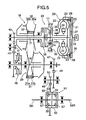
- the forward/backward travel switching mechanism 33 includes a sun gear 34 fixed to the main shaft 17, a ring gear 35 rotatably disposed to surround an outer periphery of the sun gear 34, a carrier 36 relatively rotatably supported on the main shaft 17, and a plurality of planetary gears 37 rotatably supported on the carrier 36 and meshed simultaneously with the sun gear 34 and the ring gear 35.
- the sun gear 34 (namely, the main shaft 17) of the forward/backward travel switching mechanism 33 is capable of being coupled to the driving pulley 30 through a wet multi-plate type forward clutch 38, and the carrier 36 is capable of being coupled to the casing 11 through a wet multi-plate type reverse brake 39.
- the sun gear 34 integral with the main shaft 17 is coupled to the driving pulley 30 through the forward clutch 38, so that the driving pulley 30 is rotated in unison with the main shaft 17. Therefore, when the forward clutch 38 is in an engaged state, the deceleration by the forward/backward travel switching mechanism 33 is not conducted, and the rotation of the main shaft 17 is transmitted to the driving pulley 30 at the same speed and in the same direction.
- the carrier 36 When the reverse brake 39 of the forward/backward travel switching mechanism 33 is brought into an engaged state during backward traveling of the vehicle, the carrier 36 is coupled to the casing 11, whereby the rotation of the sun gear 34 integral with the main shaft 17 is transmitted through the planetary gears 37 and the ring gear 35 to the driving pulley 30, so that the driving pulley 30 is rotated at a speed reduced relative to the main shaft 17 and in the reverse direction.
- a main first-speed gear 40 fixed to a left end of the main shaft 17 is meshed with an idling first-speed gear 42 fixed to an idling shaft 41.
- the idling first-speed gear 42 is meshed with a counter first-speed gear 45 supported through a one-way clutch 44 on a hub 43 which is rotatable relative to the counter shaft 18. This forms a stepped transmission path disposed in parallel to the belt-type continuously variable transmission 29.
- the hub 43 of the counter first-speed gear 45 is capable of being coupled to the counter shaft 18 through a wet multi-plate type LOW clutch 46.
- a final driving gear 47 provided at a right end of the counter shaft 18 is meshed with a first reduction gear 49 fixed to a reduction shaft 48.
- a second reduction gear 50, fixed to the reduction shaft 48, is meshed with a final driven gear 53 fixed to a differential box 52 of a differential gear 51.
- the differential gear 51 is of a well-known type, and comprises differential pinions 55, 55 relatively turnably supported on a pinion shaft 54 mounted in the differential box 52, and differential side gears 57, 57 which are fixed to left and right axles 56L and 56R inserted into the differential box 52 and which are meshed with the differential pinions 55, 55.
- the forward clutch 38 and the reverse brake 39 of the forward/backward travel switching mechanism 33 are released, and the LOW clutch 46 is brought into the engaged state.
- the rotation of the crankshaft 19 of the engine E is transmitted to left and right driven wheels through a path comprising the torque converter 20 ⁇ the main shaft 17 ⁇ the main first-speed gear 40 ⁇ the idling first-speed gear 42 ⁇ the counter first-speed gear 45 ⁇ the one-way clutch 44 ⁇ the LOW clutch 46 ⁇ the counter shaft 18 ⁇ the final driving gear 47 ⁇ the first reduction gear 49 ⁇ the second reduction gear 50 ⁇ and the final driven gear 53 ⁇ the differential gear 51 ⁇ and the axles 56L and 56R.
- the main shaft 17 and the counter shaft 18 can be rotated in the same direction to cause the vehicle to travel forwards, because the idling first-speed gear 42 is interposed between the main first-speed gear 40 and the counter first-speed gear 45.
- a reduction ratio between the main first-speed gear 40 and the counter first-speed gear 45 assumes a value suitable for starting the vehicle.
- the reduction ratio is set at a value closer to the LOW side from that of the belt-type continuously variable transmission 29 in a lowest-speed state.
- the reduction ratio in the lowest-speed state of the belt-type continuously variable transmission 29 assumes a value slightly closer to an OD from the reduction ratio between the main first-speed gear 40 and the counter first-speed gear 45. Therefore, a difference in rotation occurs between the counter shaft 18 and the counter first-speed gear 45 during a short time until the LOW clutch 46 is released, but such difference in rotation is absorbed by the slipping of the one-way clutch 44.
- the start of the forward travel provided by the main first-speed gear 40, the idling first-speed gear 42 and the counter first-sped gear 45 can be smoothly shifted to forward traveling by means of the belt-type continuously variable transmission 29.
- the gear ratio of the belt-type continuously variable transmission 29 is controlled between LOW and OD.
- the forward clutch 38 and the LOW clutch 46 of the forward/backward travel switching mechanism 33 are released, and the reverse brake 39 is brought into the engaged state.
- the rotation of the crankshaft of the engine E is transmitted to the left and right driven wheels through a path comprising the torque converter 20 ⁇ the main shaft 17 ⁇ the sun gear 34 ⁇ the planetary gears 37 ⁇ the ring gear 35 ⁇ the driving pulley 30 ⁇ the metal belt 32 ⁇ the driven pulley 31 ⁇ the counter shaft 18 ⁇ the final driving gear 47 ⁇ the first reduction gear 49 ⁇ the second reduction gear 50 ⁇ the final driven gear 53 ⁇ the differential gear 51 ⁇ and the axles 56L and 56R.
- the backward travel of the vehicle becomes possible, because the rotational direction of the ring gear 35 is opposite from the rotational direction of the sun gear 34 of the forward/backward travel switching mechanism 33.
- the reduction ratio between the main first-speed gear 40 and the counter first-speed gear 45 is set at the value closer to the LOW side from the reduction ratio of the belt-type continuously variable transmission 29 in the lowest speed state.
- a total reduction ratio of the reduction ratio of the forward/backward travel switching mechanism 33 and the reduction ratio of the belt-type continuously variable transmission 29 in the lowest sped state can be substantially equalized to the reduction ratio between the main first-speed gear and the counter first-speed gear 45.
- the belt-type continuously variable transmission 29 has been illustrated as a continuously variable transmission in the embodiment, but a continuously variable transmission other than the belt-type continuously variable transmission 29 can be employed in the present invention.
- a difference between gear ratios at the start of forward travel and at the start of backward travel is minimized, while using a single-pinion type planetary gear mechanism.
- the continuously variable gear path includes a forward/backward travel switching mechanism comprising a single-pinion type planetary gear mechanism, and a belt-type continuously variable transmission.
- a multi-stage gear path comprising gears is set at a gear ratio closer to a LOW side from that of the belt-type continuously variable transmission.
- a difference between the gear ratios in the multi-stage gear path and the continuously variable gear path can be minimized by using the multi-stage gear path at the start of forward travel of a vehicle and using the continuously variable gear path at the start of backward travel of the vehicle.
- the forward traveling and the backward traveling are switched over from one to another, it is unnecessary to suddenly change the gear ratio of the belt-type continuously variable transmission, which can contribute to an improvement in durability of belt-type continuously variable transmission.
Landscapes
- Engineering & Computer Science (AREA)
- General Engineering & Computer Science (AREA)
- Mechanical Engineering (AREA)
- Transmission Devices (AREA)
Claims (3)
- Système de transmission de puissance dans un véhicule, comprenant un chemin d'entraînement (M) variable continu et un chemin d'entraînement multiniveau (40-44) fourni en parallèle pour transmettre une force d'entraînement d'un moteur (E) aux roues d'entraînement,
dans lequel le chemin d'entraînement (M) variable continu inclut un mécanisme de vitesse variable continu (29) et un mécanisme de commutation (33) de trajet avant/arrière de type à pignon unique adapté pour recevoir l'entrée de la force d'entraînement du moteur (E) par l'intermédiaire d'un planétaire (34),
caractérisé en ce que
le mécanisme de commutation (33) de trajet avant/arrière de type à pignon unique est adapté pour faire sortir la force d'entraînement vers le mécanisme d'entraînement variable continu (29) par l'intermédiaire d'une couronne (35) ; et
en ce que le chemin d'entraînement multiniveau (40-44) est défini par un ratio de réduction plus proche d'un côté FAIBLE que celui du mécanisme d'entraînement variable continu (29) dans l'état de vitesse la plus faible de celui-ci. - Système de transmission de puissance dans un véhicule selon la revendication 1, dans lequel le ratio d'entraînement dans le chemin d'entraînement multiniveau (40-44) et le ratio d'entraînement dans le chemin d'entraînement variable continu (M) sont définis substantiellement par la même valeur, lorsque le mécanisme d'entraînement variable (29) est dans un état de vitesse la plus faible pendant un trajet en marche arrière.
- Système de transmission de puissance dans un véhicule selon la revendication 1, dans lequel le planétaire (34) est fixé sur un arbre principal (17) du système de transmission de puissance et un entraînement principal de première vitesse (40) du chemin d'entraînement multiniveau (40-44) est fixé à l'arbre principal (17).
Applications Claiming Priority (2)
| Application Number | Priority Date | Filing Date | Title |
|---|---|---|---|
| JP2002239542A JP3954928B2 (ja) | 2002-08-20 | 2002-08-20 | 車両の動力伝達装置 |
| JP2002239542 | 2002-08-20 |
Publications (3)
| Publication Number | Publication Date |
|---|---|
| EP1391636A2 EP1391636A2 (fr) | 2004-02-25 |
| EP1391636A3 EP1391636A3 (fr) | 2005-06-08 |
| EP1391636B1 true EP1391636B1 (fr) | 2007-10-03 |
Family
ID=31185181
Family Applications (1)
| Application Number | Title | Priority Date | Filing Date |
|---|---|---|---|
| EP03018456A Expired - Lifetime EP1391636B1 (fr) | 2002-08-20 | 2003-08-14 | Système de transmission de puissance pour vehicule |
Country Status (4)
| Country | Link |
|---|---|
| US (1) | US6855084B2 (fr) |
| EP (1) | EP1391636B1 (fr) |
| JP (1) | JP3954928B2 (fr) |
| DE (1) | DE60316639T2 (fr) |
Families Citing this family (22)
| Publication number | Priority date | Publication date | Assignee | Title |
|---|---|---|---|---|
| CN1578890B (zh) * | 2002-09-30 | 2010-05-26 | 乌尔里克·罗斯 | 传动机构 |
| US7278939B2 (en) * | 2003-02-14 | 2007-10-09 | Honda Motor Co., Ltd. | Power transmission |
| US7822524B2 (en) * | 2003-12-26 | 2010-10-26 | Toyota Jidosha Kabushiki Kaisha | Vehicular drive system |
| ITBO20040017A1 (it) * | 2004-01-16 | 2004-04-16 | Cnh Italia Spa | Trasmissione cvt per autoveicoli, in particolare pre trattori agricoli. |
| US7504691B2 (en) * | 2004-10-07 | 2009-03-17 | Fairchild Semiconductor Corporation | Power trench MOSFETs having SiGe/Si channel structure |
| WO2006042040A2 (fr) * | 2004-10-07 | 2006-04-20 | Fairchild Semiconductor Corporation | Transistors de puissance a grille mos a bande interdite modifiee |
| JP2008038921A (ja) * | 2006-08-01 | 2008-02-21 | Exedy Corp | 動力伝達装置 |
| DE102006039608A1 (de) * | 2006-08-24 | 2008-04-10 | Rolls-Royce Deutschland Ltd & Co Kg | Anordnung zur Energieentnahme bei einem Zwei-Wellen-Triebwerk |
| JP2008196670A (ja) * | 2007-02-15 | 2008-08-28 | Nsk Warner Kk | ブレーキバンドを用いた前後進切換え機構 |
| US7825465B2 (en) * | 2007-12-13 | 2010-11-02 | Fairchild Semiconductor Corporation | Structure and method for forming field effect transistor with low resistance channel region |
| RU2474500C2 (ru) * | 2008-04-14 | 2013-02-10 | Хонда Мотор Ко., Лтд. | Привод для гибридного транспортного средства |
| JP5386116B2 (ja) * | 2008-06-20 | 2014-01-15 | ボーグワーナー インコーポレーテッド | サイレントチェーン |
| NL1037587C2 (nl) * | 2009-12-24 | 2011-06-27 | Bosch Gmbh Robert | Automatische overbrenging met een koppelomvormer, een dnr-tandwielgroep en een cvt-eenheid en werkwijze voor het bedrijf daarvan. |
| JP5565093B2 (ja) * | 2010-05-20 | 2014-08-06 | 日産自動車株式会社 | 駆動力伝達装置 |
| EP2853776B1 (fr) | 2012-05-23 | 2019-10-09 | Toyota Jidosha Kabushiki Kaisha | Dispositif de transmission d'énergie pour véhicule |
| BR112014028994A2 (pt) | 2012-05-23 | 2017-06-27 | Toyota Motor Co Ltd | dispositivo de transmissão de potência para veículo |
| JP5861777B2 (ja) | 2012-05-23 | 2016-02-16 | トヨタ自動車株式会社 | 車両用動力伝達装置 |
| US9371896B2 (en) | 2012-05-23 | 2016-06-21 | Toyota Jidosha Kabushiki Kaisha | Power transmission unit for vehicle |
| US10036433B2 (en) * | 2016-06-14 | 2018-07-31 | Ford Global Technologies, Llc | Clutch for continuously variable transmission |
| FR3056276A1 (fr) * | 2016-09-19 | 2018-03-23 | Peugeot Citroen Automobiles Sa | Transmission mecanique a variation continue avec train epicycloidal integre |
| KR20200102031A (ko) * | 2019-02-20 | 2020-08-31 | 현대자동차주식회사 | 차량용 무단 변속 동력전달 장치 |
| CN114165573B (zh) * | 2021-12-15 | 2024-09-27 | 芜湖万里扬变速器有限公司 | 纵置无级变速器 |
Family Cites Families (8)
| Publication number | Priority date | Publication date | Assignee | Title |
|---|---|---|---|---|
| JPS5697661A (en) * | 1979-12-28 | 1981-08-06 | Toyota Motor Corp | Automatic transmission |
| DE3212769A1 (de) * | 1982-04-06 | 1983-10-06 | Volkswagenwerk Ag | Getriebeanordnung |
| JPS6314228A (ja) | 1986-07-03 | 1988-01-21 | Fujitsu Ltd | 表示装置 |
| ES2068047B1 (es) * | 1991-05-31 | 1997-08-16 | Aragonesa De Equipamientos Par | Cambio de velocidades mecanico continuo. |
| KR100262593B1 (ko) * | 1996-12-17 | 2000-08-01 | 정몽규 | 차량용 무단 변속장치 |
| US5895335A (en) * | 1998-02-20 | 1999-04-20 | General Motors Corporation | Continuously variable powertrain |
| JP3468456B2 (ja) * | 1999-07-14 | 2003-11-17 | 本田技研工業株式会社 | 車両用動力伝達装置の停止制御装置 |
| JP3469182B2 (ja) * | 2000-09-05 | 2003-11-25 | 本田技研工業株式会社 | 車両用無段変速機の制御装置 |
-
2002
- 2002-08-20 JP JP2002239542A patent/JP3954928B2/ja not_active Expired - Fee Related
-
2003
- 2003-08-14 EP EP03018456A patent/EP1391636B1/fr not_active Expired - Lifetime
- 2003-08-14 DE DE60316639T patent/DE60316639T2/de not_active Expired - Fee Related
- 2003-08-19 US US10/643,165 patent/US6855084B2/en not_active Expired - Lifetime
Also Published As
| Publication number | Publication date |
|---|---|
| US6855084B2 (en) | 2005-02-15 |
| US20040106488A1 (en) | 2004-06-03 |
| DE60316639D1 (de) | 2007-11-15 |
| EP1391636A3 (fr) | 2005-06-08 |
| EP1391636A2 (fr) | 2004-02-25 |
| JP3954928B2 (ja) | 2007-08-08 |
| DE60316639T2 (de) | 2008-01-31 |
| JP2004076876A (ja) | 2004-03-11 |
Similar Documents
| Publication | Publication Date | Title |
|---|---|---|
| US6855084B2 (en) | Power transmission system in vehicle | |
| US4455888A (en) | Automotive transmission | |
| EP0943841B1 (fr) | Traction toutes roues motrices avec double mode de fonctionnement et variateur continu de vitesse | |
| US5944628A (en) | Continuously variable transmission for vehicles | |
| US5931760A (en) | Dual mode continuously variable transmission having multiple torque input paths | |
| EP0943839A2 (fr) | Transmission à variation continue à deux modes de fonctionnement pour véhicule à quatre roues motrices | |
| US5961414A (en) | Dual mode continuously variable transmission having multiple torque input paths | |
| EP0943840B1 (fr) | Traction toutes roues motrices avec double mode de fonctionnement et variateur continu de vitesse | |
| KR100204956B1 (ko) | 차량용 자동 변속기의 파워 트레인 | |
| US4550629A (en) | Continuously variable speed transmission for motor vehicles | |
| JP4035423B2 (ja) | 変速機 | |
| KR20020062068A (ko) | 높은 변속효율과 내구성을 갖는 무단 변속장치 | |
| KR20080107088A (ko) | 고효율 무단변속기 | |
| JPH0571628A (ja) | 無段変速機の変速制御装置 | |
| KR100196803B1 (ko) | 차량용 무단 변속장치 | |
| KR100260166B1 (ko) | 차량용 무단 변속장치 | |
| KR0183219B1 (ko) | 차량용 무단 변속장치 | |
| KR0183236B1 (ko) | 무단 변속이 가능한 차량용 자동변속기의 파워트레인 | |
| KR0154072B1 (ko) | 차량용 무단 변속기 | |
| KR0168388B1 (ko) | 차량용 무단 변속장치 | |
| KR200189179Y1 (ko) | 차량용 무단 변속장치 | |
| KR20020062066A (ko) | 높은 변속효율과 내구성을 갖는 무단 변속장치 | |
| KR0154075B1 (ko) | 차량용 무단 변속장치 | |
| KR100199168B1 (ko) | 차량용 무단 변속장치 | |
| KR200195843Y1 (ko) | 차량용 무단 변속장치 |
Legal Events
| Date | Code | Title | Description |
|---|---|---|---|
| PUAI | Public reference made under article 153(3) epc to a published international application that has entered the european phase |
Free format text: ORIGINAL CODE: 0009012 |
|
| AK | Designated contracting states |
Kind code of ref document: A2 Designated state(s): AT BE BG CH CY CZ DE DK EE ES FI FR GB GR HU IE IT LI LU MC NL PT RO SE SI SK TR |
|
| AX | Request for extension of the european patent |
Extension state: AL LT LV MK |
|
| PUAL | Search report despatched |
Free format text: ORIGINAL CODE: 0009013 |
|
| AK | Designated contracting states |
Kind code of ref document: A3 Designated state(s): AT BE BG CH CY CZ DE DK EE ES FI FR GB GR HU IE IT LI LU MC NL PT RO SE SI SK TR |
|
| AX | Request for extension of the european patent |
Extension state: AL LT LV MK |
|
| 17P | Request for examination filed |
Effective date: 20050713 |
|
| AKX | Designation fees paid |
Designated state(s): DE FR GB IT NL |
|
| GRAP | Despatch of communication of intention to grant a patent |
Free format text: ORIGINAL CODE: EPIDOSNIGR1 |
|
| GRAS | Grant fee paid |
Free format text: ORIGINAL CODE: EPIDOSNIGR3 |
|
| GRAA | (expected) grant |
Free format text: ORIGINAL CODE: 0009210 |
|
| AK | Designated contracting states |
Kind code of ref document: B1 Designated state(s): DE FR GB IT NL |
|
| REG | Reference to a national code |
Ref country code: GB Ref legal event code: FG4D |
|
| REF | Corresponds to: |
Ref document number: 60316639 Country of ref document: DE Date of ref document: 20071115 Kind code of ref document: P |
|
| NLV1 | Nl: lapsed or annulled due to failure to fulfill the requirements of art. 29p and 29m of the patents act | ||
| PG25 | Lapsed in a contracting state [announced via postgrant information from national office to epo] |
Ref country code: NL Free format text: LAPSE BECAUSE OF FAILURE TO SUBMIT A TRANSLATION OF THE DESCRIPTION OR TO PAY THE FEE WITHIN THE PRESCRIBED TIME-LIMIT Effective date: 20071003 |
|
| EN | Fr: translation not filed | ||
| PLBE | No opposition filed within time limit |
Free format text: ORIGINAL CODE: 0009261 |
|
| STAA | Information on the status of an ep patent application or granted ep patent |
Free format text: STATUS: NO OPPOSITION FILED WITHIN TIME LIMIT |
|
| 26N | No opposition filed |
Effective date: 20080704 |
|
| PG25 | Lapsed in a contracting state [announced via postgrant information from national office to epo] |
Ref country code: FR Free format text: LAPSE BECAUSE OF FAILURE TO SUBMIT A TRANSLATION OF THE DESCRIPTION OR TO PAY THE FEE WITHIN THE PRESCRIBED TIME-LIMIT Effective date: 20080704 |
|
| PGFP | Annual fee paid to national office [announced via postgrant information from national office to epo] |
Ref country code: DE Payment date: 20080829 Year of fee payment: 6 |
|
| PGFP | Annual fee paid to national office [announced via postgrant information from national office to epo] |
Ref country code: GB Payment date: 20080827 Year of fee payment: 6 |
|
| GBPC | Gb: european patent ceased through non-payment of renewal fee |
Effective date: 20090814 |
|
| PG25 | Lapsed in a contracting state [announced via postgrant information from national office to epo] |
Ref country code: DE Free format text: LAPSE BECAUSE OF NON-PAYMENT OF DUE FEES Effective date: 20100302 |
|
| PG25 | Lapsed in a contracting state [announced via postgrant information from national office to epo] |
Ref country code: GB Free format text: LAPSE BECAUSE OF NON-PAYMENT OF DUE FEES Effective date: 20090814 |
|
| PG25 | Lapsed in a contracting state [announced via postgrant information from national office to epo] |
Ref country code: IT Free format text: LAPSE BECAUSE OF NON-PAYMENT OF DUE FEES Effective date: 20080831 |