EP1391686A1 - Verfahren und Vorrichtung zur Lokalisierung von Objekten mittels einer optischen Messtechnik - Google Patents
Verfahren und Vorrichtung zur Lokalisierung von Objekten mittels einer optischen Messtechnik Download PDFInfo
- Publication number
- EP1391686A1 EP1391686A1 EP03291985A EP03291985A EP1391686A1 EP 1391686 A1 EP1391686 A1 EP 1391686A1 EP 03291985 A EP03291985 A EP 03291985A EP 03291985 A EP03291985 A EP 03291985A EP 1391686 A1 EP1391686 A1 EP 1391686A1
- Authority
- EP
- European Patent Office
- Prior art keywords
- pattern
- images
- robot
- relief
- light
- Prior art date
- Legal status (The legal status is an assumption and is not a legal conclusion. Google has not performed a legal analysis and makes no representation as to the accuracy of the status listed.)
- Withdrawn
Links
- 238000000034 method Methods 0.000 title claims description 56
- 238000000691 measurement method Methods 0.000 title 1
- 230000003287 optical effect Effects 0.000 claims abstract description 37
- 238000012545 processing Methods 0.000 claims abstract description 22
- 230000004807 localization Effects 0.000 claims description 24
- 238000009432 framing Methods 0.000 claims description 4
- 239000011159 matrix material Substances 0.000 claims 1
- 238000005259 measurement Methods 0.000 description 25
- 230000008569 process Effects 0.000 description 18
- 238000004364 calculation method Methods 0.000 description 6
- 238000004458 analytical method Methods 0.000 description 3
- 238000012795 verification Methods 0.000 description 3
- 230000008570 general process Effects 0.000 description 2
- 238000009434 installation Methods 0.000 description 2
- 241001669679 Eleotris Species 0.000 description 1
- 230000032683 aging Effects 0.000 description 1
- 238000013459 approach Methods 0.000 description 1
- 230000000712 assembly Effects 0.000 description 1
- 238000000429 assembly Methods 0.000 description 1
- 238000010835 comparative analysis Methods 0.000 description 1
- 230000000052 comparative effect Effects 0.000 description 1
- 230000000295 complement effect Effects 0.000 description 1
- 239000000470 constituent Substances 0.000 description 1
- 230000001419 dependent effect Effects 0.000 description 1
- 238000001514 detection method Methods 0.000 description 1
- 238000006073 displacement reaction Methods 0.000 description 1
- 230000000694 effects Effects 0.000 description 1
- 238000001914 filtration Methods 0.000 description 1
- 239000011521 glass Substances 0.000 description 1
- 239000003292 glue Substances 0.000 description 1
- 229910052736 halogen Inorganic materials 0.000 description 1
- 150000002367 halogens Chemical class 0.000 description 1
- 238000009776 industrial production Methods 0.000 description 1
- 230000010354 integration Effects 0.000 description 1
- 238000005304 joining Methods 0.000 description 1
- 238000004519 manufacturing process Methods 0.000 description 1
- 239000003550 marker Substances 0.000 description 1
- 239000000463 material Substances 0.000 description 1
- 239000002184 metal Substances 0.000 description 1
- 230000035939 shock Effects 0.000 description 1
- 238000012360 testing method Methods 0.000 description 1
Images

Classifications
-
- B—PERFORMING OPERATIONS; TRANSPORTING
- B60—VEHICLES IN GENERAL
- B60J—WINDOWS, WINDSCREENS, NON-FIXED ROOFS, DOORS, OR SIMILAR DEVICES FOR VEHICLES; REMOVABLE EXTERNAL PROTECTIVE COVERINGS SPECIALLY ADAPTED FOR VEHICLES
- B60J1/00—Windows; Windscreens; Accessories therefor
- B60J1/004—Mounting of windows
-
- G—PHYSICS
- G01—MEASURING; TESTING
- G01B—MEASURING LENGTH, THICKNESS OR SIMILAR LINEAR DIMENSIONS; MEASURING ANGLES; MEASURING AREAS; MEASURING IRREGULARITIES OF SURFACES OR CONTOURS
- G01B11/00—Measuring arrangements characterised by the use of optical techniques
- G01B11/002—Measuring arrangements characterised by the use of optical techniques for measuring two or more coordinates
Definitions
- the present invention relates to a localization method of an object by visiometry.
- object here also designates a separate entity whole, than a component of a larger piece.
- Localization is thus considered in the broad sense, and it includes determining not only the position of an object, but also orientation in space and dimensions of a room, by obtaining and relating the spatial coordinates of many of the objects that make it up. Localization can thus be performed in relation to an absolute benchmark, or in relation to a reference specific to the part.
- the process according to the invention uses the technique of visiometry, the general principle of which is based on the generation of a image and on the exploitation of that image by means of signal processing.
- the invention also relates to a device for setting using such a method.
- the method and the device according to the invention are in particular intended to be used in assembly lines automated, for all stages during which it is necessary to calculate the position of an object, or measure this object or one of its parts, in order for example to realize its assembly in a predetermined position with other objects having also been located, by the same process or by any other.
- the invention finds particular application in the sector in the automotive industry, but also in any other sector in which it is advantageous to operate by automated manufacturing.
- the main objectives of the assembly lines are the efficiency and quality of the assemblies.
- the invention applies to all types and to all shapes of objects. It uses more particularly the zones of the object presenting a relief, or a contrast on their surface. By relief, we hears any element whose surface extends over two planes different inclinations.
- the relief is marked by an edge, the profile can be straight or blunt, straight or curved.
- the area to contrast is defined here as having an element which gives a difference in brightness under homogeneous lighting by diffuse light. Such an element can be a variation of tint on an object. Note that a hole in an object is treated in the context of the invention as falling within a contrast zone, and not a relief area.
- patent EP 0 280 941 describes a process car wheel alignment meter, which uses a visiometry technique, and which is suitable for integration in an industrial assembly line.
- This process consists of observe with a camera the deformation of a laser light projected onto the wheel, and to be generated from the image formed of the coordinates for this wheel. lt's not about coordinates in three dimensions but simply two coordinates in a plane, and the inclination of the wheel relative to a vertical plane is determined in addition by comparative analysis of the intensity of the light signal reflected by each illuminated point of the wheel.
- the process described by this patent is specifically directed to this particular application, and it can only be implemented to different issues.
- the invention aims to provide a method for locating a object usable in automated chains, which allows measure different parameters on a given object and which generates reliable and accurate results.
- the invention also aims that, in more advanced embodiments, the device for setting work of the process which it proposes is designed so that a part of this device can be used on board a robot assembly of parts, to allow localization by the same device of different parts to be assembled in the same assembly step and located in different places in the chain.
- the invention relates to a method for locating an object. in a three-dimensional space, according to which we project a pattern of geometrically structured light towards a relief area of the object, in a direction of projection transverse to the profile of this relief.
- We capture two flat images of the pattern by detecting the light reflected by the object in two directions of observation differently inclined to the projection direction of the pattern.
- the projected pattern consists of at least one rectilinear line, which gives place at a point of deformation characteristic of the relief on each of the two images.
- a first level of verification we check that the entire pattern issued is found on each of the two images.
- the pattern of structured light is composed of a single line
- the pattern consists of a plurality of lines giving rise to a plurality of deformation points characteristics of the relief on each of the images. It is decided that there has agreement between the two images when for several of these points two different sets of spatial coordinates, calculated at from the two images, are coincident. We then validate as that object location coordinates the coordinates the points for which the two games are coincident.
- the invention thus quite advantageously ensures that can exploit a redundancy of information coming from two different sources, which gives rise to a reliability of the result of localization all the more increased.
- These spatial coordinates can then be validly considered as coordinates of location of the object.
- we validate the spatial coordinates of several characteristic points so that it is possible to draw a vector passing through these different points and marking the relief observed. We know for sure not one, but several object location information.
- the projected light pattern is made up of a number sufficiently important to have a coincidence of the two spatial coordinate sets for enough deformation points to get rich location information.
- the invention also advantageously provides that, in preferred embodiments, localization be shelved if we do not obtain agreement of the two images on a number enough of the constituent features of the light pattern, especially on at least three of these traits.
- the invention also meets the characteristics detailed below, implemented separately or in each of their technically effective combinations.
- the projected structured light is monochromatic, long wave.
- the light reflected by the object is then detected after filtering of light signals of wavelength outside of a narrow band framing the wavelength of the projected light. This advantageously makes it possible to improve the signal / noise ratio of background.
- the equipment designed for the implementation of the invention advantageously allows that one can also locate any object, and even in particular when the conditions of work do not allow to carry out a relief detection. It's the case for example when it comes to locating a window to be assembled in an assembly line, or any other object consisting of material with a high capacity for reflecting light, which prohibits the use of a geometrically structured light pattern.
- alternately to the projection of structured light we illuminate on the other hand a zone in contrast of the object by a diffuse light. We capture two different images of this contrast area in detecting the light reflected by the object in two directions of different observations, and we determine from the two images captured the location of the contrast.
- two different kinds of images can be captured, depending on whether we observe a relief area of the object on which is projected a pattern of structured light, or that we observe an area contrast of this object lit by diffuse light.
- the invention also relates to a device for setting implementing the process which it proposes.
- This device comprises at minus an optical head in which a source of geometrically structured light of given wavelength to project to a relief area of the object to locate a pattern of this light in a determined direction of projection.
- This source is in particular a laser light source.
- two optical sensors oriented according to viewing directions each tilted differently from to the direction of projection of the structured light pattern, to capture two different images of the pattern reflected by the object, and two optical filters, each placed in front of one of the sensors and presenting a narrow bandwidth framing the wavelength of the structured light.
- the optical head is associated with a device image acquisition and processing adapted to locate on each of the images captured a characteristic element of the relief is resulting in a distortion of the pattern on the image, to check the agreement between the images captured on at least part of the pattern, to calculate the spatial coordinates of the element characteristic from the two captured images and to validate automatically these spatial coordinates as coordinates of location of the object.
- the device comprises a plurality of optical heads associated with the same image acquisition and processing device.
- the optical head further includes a diffuse light source.
- diffuse light is almost monochromatic and in the same range of wavelengths than structured light, so the filters optics located in front of the sensors let it pass.
- the source of Diffuse light is in particular an array of diodes.
- the same device thus advantageously allows locate relief areas on the one hand, and areas on the other contrast. It can therefore be used for localization successive of several objects of different configurations, which represents a definite economic advantage.
- the device is further associated with means for controlling a robot for assembling parts in a serial assembly line automated.
- the device according to the invention can advantageously be used to locate a part in an assembly line in automated series.
- a or several optical heads are on board a robot parts assembly. Localization is notably carried out in observing successively, each time by means of two heads optics associated with the same acquisition and processing device image and embedded on the robot, two groups of two zones to relief or optionally contrast areas presented by the room. Each of the zones is observed by only one of the heads. The zones are advantageously chosen so that their location provides enough information to determine the position and dimensions of the room.
- the invention also relates to a method of mounting in series in an automated windshield chain on frames of cars, using the device according to the invention.
- This process involves the successive repetition of the cycle of stages comprising the moving the robot, conventionally controlled, to a position appropriate to the location of one of the windshields, then the location of this windshield by the process of locating contrasts according to the invention, by observation of four zones to contrast presented by the windshield by two optical heads associated with the same image acquisition and processing device and embedded on the robot.
- the cycle then includes entering the windshield by the robot.
- the next steps are moving the robot to a position suitable for the location of one of the frames, then the localization of this frame by the localization process of reliefs according to the invention, by observation of four relief areas presented by the frame by the same two optical heads.
- the cycle includes the installation of the windshield on the frame by the robot. It is advantageously provided that the control means of the robot integrate means for memorizing the coordinates of location determined by the device according to the invention.
- This general process of assembling parts in a assembly line thus integrates, in two distinct stages of a otherwise classic general process for everything related to movements and other robot actions, two forms of implementation different work of the localization method according to the invention.
- the preferred embodiment of the invention described here corresponds to one of the most complex cases to implement, where several measurements are to be made on several different parts, in order to guide a robot to carry out an operation in a assembly line for the automotive industry. To do this, several optical heads are on board the robot.
- the assembly step concerned is the installation of a windshield on a car.
- the positions of the windscreen and the frame of the car intended for receive are not known precisely, but approximately plus or minus about 1 cm in all directions.
- their dimensions vary slightly from room to another.
- the robot has no fixed information on the position of the pieces in space, nor on their dimensions.
- the only predetermined data concerns the shape of the windshield and the frame of the car.
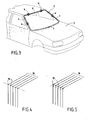
- Figure 1 shows a schematic view of the part of the assembly line within which the invention is used.
- a robot 1 must install a windshield 2 on a car 3.
- the movements of robot 1 are conventionally controlled by processors programmed for this purpose.
- Robot 1 is articulated. It presents in particular four axes hinge. It carries a rectangular frame 19 which is provided four suction cups 4 for gripping the windshield.
- Car 3 has a frame 5, hollow and shaped rectangular, which is intended to receive the windshield. This frame is delimited by two uprights 6 and 7 and two sleepers, one sleeper upper 8 and lower cross member 9. Car 2 is brought to robot 1 by a conveyor.
- the windshield 2 arrives at the level of the robot 1 also carried by a conveyor. It has a generally rectangular shape, dimensions approximately equal to those of box 5. It is delimited by lateral contours 6 'and 7', and longitudinal 8 'and 9'.
- the robot is equipped with a visiometry device, which has two optical heads on board the robot, in particular carried by the frame 19, and an acquisition and processing device image, or calculator, associated with them, to allow it to locate the windshield 2 on the one hand and the frame 5 of the car intended to receive the windshield 2 on the other hand.
- the visiometry device calculator and processors controlling robot 1 permanently communicate one with the other.
- the dimensions of the windshield 2 and the car 3 being slightly variable depending on each room, the device visiometry also has the role of determining the dimensions frame 5 and windshield 2, so that robot 1 can install the windshield 2 in a centered position relative to the frame 5, allowing to obtain an optimal aesthetic effect.
- An optical head 10 is illustrated in FIG. 2.
- a housing 11 which is compact and small.
- the head 10 is shown seen from above, the cover of the housing 11 having been removed, to show the different internal components of the head.
- the housing 11 contains a light source geometrically structured 12, which is preferably a source of laser light, which makes it possible to locate the reliefs of an object.
- a light source geometrically structured 12 which is preferably a source of laser light, which makes it possible to locate the reliefs of an object.
- other geometrically structured light sources such as an illuminated grid, can also be used.
- the laser source emits a determined light pattern 16.
- the structured light pattern is a series of straight lines parallel, in particular consisting of 5 to 11 lines.
- the precision of the measurement will be all the better as the number of lines is important. In a preferred embodiment of the invention, it is equal to 9.
- the head includes also a diffuse light source 13. It can thus also be used for the analysis of contrasts on an object.
- Such a diffuse light source 13 finds many applications in industrial production lines.
- a example of use consists in particular of searching in a piece a through hole. Illuminated by diffuse light, the hole appears darker while the rest of the room is more luminous.
- the diffuse light source 13 is an array of emission diodes of light, distributed over the entire front face of the housing 11. These have the advantage of not aging, turning on and off quickly, and emit an almost monochromatic light.
- the number and power of the diodes is variable depending on the application needs. Any other diffuse light source can also be used in the context of the invention, in particular a halogen lighting.
- geometrically structured light 12 or diffused light 13 is used.
- An optical filter 15, 15 ′ is placed in front of each of the cameras 14, 14 '.
- Each of these filters has a bandwidth narrow framing the wavelength of the laser light, so to eliminate all light signals of wavelengths different, including disturbances from ambient lighting.
- the diodes 13 are chosen from so as to emit in the same wavelength range as the laser light 12, so that the filter 15, 15 'lets through the same way the light reflected by the object, whether it was emitted by the laser source 12 or by the diodes 13.
- the laser source 12, which is monochromatic, and the diodes 13, which are practically so emit red light, with a wavelength close to 700 nm, and the filters let in only the light around this wave length. This allows quite advantageously improve contrast compared to ambient lighting.
- the housing 11 has opaque walls. It is provided with several transparent windows, which allow on the one hand the projection of light, and secondly observation by cameras.
- Measurements are thus carried out on three zones different from each room.
- Each head 10 thus performs two measurements, at two separate places in each room.
- the robot 1 moves the heads 10 to the adequately position for the second set of measures.
- optical heads in a fixed position or mobile is mainly based, for each application, on economic criteria. If a large number of measurements are necessary, using a smaller number of heads, which will be loaded onto a robot, we will realize the financial savings of buying multiple heads. In practice, we also observe in this case a gain in terms of flexibility of use. He can however be advantageous not to limit the number of heads on board the robot, in order to limit the movements of this last, and therefore save cycle time. Conversely, for other applications requiring a much smaller number of measures, the use of fixed heads will be preferred, which will allow to simplify the calculations to be performed in the processing steps of the signal.
- the position of the object is in a determined case with respect to a fixed mark, and in the other with respect to a mark specific to the robot.
- the area on which the light pattern is projected geometrically structured should also be chosen.
- the measurements are carried out on particular areas of the room, which have a relief or a contrast.
- the frame 5 of the car 3 comprising uprights and sleepers all having edges, it is particularly appropriate in his case to use the structured light source, which allows the location of reliefs.
- the same two heads optics 10 will therefore be used to locate on the one hand the windshield 2 and on the other hand the frame 5, by two different integrated means one and the other in each of the heads.
- the measurement areas a, a 'and b, b 'shown in Figure 3 are chosen respectively on the upright 6, upright 7 and upper cross member 8. These zones meet the above criteria.
- Figure 2 illustrates the measurement on a particular area of the frame 5 of car 3, from an optical head 10.
- a structured light pattern 16 in particular consisting of 5 lines, is projected by the laser source 12 in a direction predetermined to area a of the car frame, in which we know from the approximate known position of the piece that find relief.
- the light pattern is directed transversely to the profile of the relief.
- the head 10 is advantageously designed, positioned and oriented in such a way that for each point in the area of work, the angle ⁇ between the axes of view 17, 17 'of the two cameras and the working distance allow to obtain the best compromise between precision and ease of use.
- a distance to the important object which will involve a narrow angle between the axes of view of the two cameras, will give a strong imprecision on the coordinate of measured depth.
- a close observation with a wide angle will make it difficult to get a equivalent lighting over the entire area on which the laser light.
- the working distance is between 10 and 50 cm, and the angle between the axes of view of the two cameras is between 10 and 50 degrees. It is notably equal to 30 degrees.
- the angle between the projection direction of the laser light and the observation plane of the cameras is advantageously equal to 90 degrees, so as to obtain a precise measurement for most configurations of objects to locate.
- the laser lines undergo a deformation on contact with the object.
- the light is reflected by the object, and the two cameras 14, 14 'observe, each at a viewing angle different, the reflected light pattern.
- Each edge of the object is finding on the path of the laser lines 16 induces a deformation of these traits.
- the lines 16 thus undergo a sudden change of direction translating for each one by a point of deformation 18 on each one images.
- the image perceived by one of the cameras 14 is represented in figure 4.
- the cameras 14, 14 record the distorted image of the pattern of light reflected by frame 5, and transmit this information to the calculator.
- the computer analyzes the signals transmitted by each of the cameras, and identifies, for each line, a point of deformation 18 corresponding to the edge of the object. He then draws a vector passing through the five points 18 thus determined.
- This vector constitutes a marking of the edge analyzed. In the cases application described here, this vector is a straight line. According to profile of the edge, it can also be a circular vector.
- the calculator uses selection criteria predetermined to select the appropriate deformation point 18. These criteria can be a predetermined direction of the change of direction, an angular value of the deformation compared to a benchmark, or, if appropriate, the verification that the five points 18 belong to the same straight line. This last criterion allows if necessary to eliminate a point inconsistent with the others. This operation generates little loss of precision, from the moment we have always at least three points to draw the vector that will mark the ridge.
- the calculator determines its position in a 3D frame specific to the head 10, by combining the data from each of the cameras 14, 14 '.
- the same operation is carried out simultaneously by means of the other optical head 10 carried by the robot 1 on another of the zones for example, area b.
- the robot then moves the 10 heads for locating by the same process the two remaining zones a ', b', each observed by one of the two heads 10. This makes it possible to accurately determine both the position and the dimensions of the frame 5 of the car 3.
- the implementation of the process is similar for the location of the four contrast zones of the windshield, the only difference that it is the diffuse light source 13 which is this time used.
- Diffused light can also advantageously be used in many other applications, for example for locating a through hole in a room.
- the calculator determines the position in space of the center of each of the ellipses, and by combining the two data, it deduce the position in space from the center of the circular hole.
- Each of the heads 10 has its own repository XYZ. Quite advantageously, the fact that the two cameras 14, 14 'are placed in the same box 11 allows them to be conveniently used in dynamic mode (ease of displacement).
- the calibration of the two cameras 14, 14 ' is carried out in factory, prior to delivery. Then just to calibrate the head 10 at the place of use, according to the specific application for which it is intended.
- Robot 1 has its own reference system fixed to the ground.
- each head 10 In order to allow robot 1 to perform its task of assembly, the data from each head 10, which are expressed relative to the head 10 repository, are communicated to its control means. It is necessary to submit beforehand robot 1 learning, in order to match its own repository and that of each of the two heads 10. Learning is carried out in a conventional manner, identical to that of robots whose role is to handle a tool. Robot 1 is equipped for this as many tool marks as on-board heads 10. A test pattern with three targets forming the basis of an east marker system used.
- the head 10 is assimilated to a virtual tip for the robot 1.
- An operator manually moves the robot 1 in front of the target until this virtual point gives the position 0,0,0 of the center of the work area. This operation is repeated by taking three or four different directions of approach from point to point pattern.
- the virtual point then learns in the same way the position of the other two targets of the target, so that the robot 1 knows, at the end of these steps, the space defined by the target.
- the optical head 10 is then positioned in front of the same target, in a position defined as its reference position, which corresponds to the 0,0,0 position of the target. It is then moved in order to learn the position of the other two points of the target, which define, with the point 0,0,0, the three-dimensional space of the pattern.
- the visiometry device and the robot 1 are then capable to work in the same space that they both learned from the pattern.
- robot 1 After learning, robot 1 is able to understand the coordinates coming from head 10, which are data in a repository that he shares with her.
- the image observed by each of the cameras 14, 14 ′ generates two position coordinates.
- the invention advantageously takes advantage of this redundancy information to provide a reliable localization process and specific.
- the coincidence of the results obtained for the location of the point by each of these two sets of coordinates determines that it there is a concordance of the two images captured by the two cameras 14, 14 'on the laser line, and therefore to validate the spatial coordinates thus obtained as reliable location coordinates of the object.
- a predetermined threshold value is used to judge whether there is or not coincidence between the two sets of spatial coordinates.
- the method according to the invention is particularly advantageous, since it uses the redundancy of information generated by the use of two cameras, to best manage a plurality of features.
- each of the features observed by one of the cameras, by a treatment carried out as just described, is compared one to one with the features observed by the other, in order to find the one who matches.
- An iterative method is thus applied trait after line, until ensuring that the two images match one with the other on a maximum number of strokes. We are then sure of the accuracy of the location, since it was carried out from a plurality of features, and its reliability, since it has been validated by a information redundancy.
- the invention advantageously ensures that even if one or more lines missing in the images, it always remains enough traits on which the redundancy of information, and which can therefore be implemented correspondence on each of the two images, to obtain a precise and reliable localization.
- a similar signal processing system is implemented whatever the shape of the geometric light pattern structured 16 used.
- the signal processing system is also substantially identical for the analysis of contrasts from a diffused light lighting.
- it offers a particularly method and device adapted to the location and determination of the dimension of parts of all types in automated assembly lines.
- the process and device according to the invention respond advantageously to concerns of efficiency and yield predominantly economic in such industries. They exploit information redundancies available from two images captured from different angles of the same pattern structured light projected to examine how far there is coincidence. It is only then that the degree of consistency between the two images meet predetermined requirements that are validated the three-dimensional coordinate information calculated at from these images. If the agreement is insufficient, we can interrupt the automated part processing process by course, and in the previous particular application, we avoid proceed to the final bonding of a windshield which would not be compliant or that would not present correctly compared to receiver frame. More generally, it is better not to process a document for which the consistency of the information position is not enough, rather than taking the risk of a shock between the robot gripper and the part.
- the concordance check carried out not for a single point, but for several points of the images captured from the same projected pattern allows the operator to decide whether the montage is valid or not. This completes advantageously by examining the degree of consistency by pairing two captured images. If all the elements (lines or points) of the projected light pattern are visible from each camera, the comparative processing of the captured images considers the elements one after the other. If the elements are not all visible by each camera, we start by matching the elements seen by each.
- frame-by-frame analysis elements allows to recognize a geometric element of the object, unambiguously. This is the case for example when all lines are visible where they end at the edge of a sheet or where they draw a curved line on the same sheet metal fold.
- a first step then consists in extracting from each image the two-dimensional coordinates of this element geometric object (straight, ellipse, circle, or other), then a second step is to calculate the coordinates in three dimensions of this object (classic stereoscopic calculation between two points or two lines). Having a good estimate of the three-dimensional position of this geometric element it's possible to return to the coordinates of the light elements in images and match them using an iterative method taking into account various constraints, among which we can choose in particular: good agreement between the elements of two cameras, good coordinate matching with respect to the element's coordinates geometric previously calculated, compliance with the scheduling light elements, for example compliance with the order of succession of lines or dots.
- this pairing can be done by example by an iterative method that examines the different possible combinations of the elements of the two images, respecting the following constraints: good concordance between the elements of the two cameras, respect for the scheduling of the light elements, that is to say in particular the respect for the order of succession of lines or points.
- this pairing or concordance check, is to examine, for each possible combination, consistency of information, and determine for which combination we have a strong coherence in checking that for all the other combinations we observe a much less coherence.
- the projected structured light pattern is preferably made up of a plurality of distinct elements such as lines or series of points.
- a complementary technique particularly advantageous in the case of a projection of points, consists in memorize the coordinates of the light elements during a calibration phase, prior to the implementation of the sensor. During the pairing step, it is thus possible to add as constraint that the coordinates of the points found must actually correspond to the coordinates of a light element learned.
- This method can be used with any type of element bright (dots, lines, or others), but it is simpler in the point case, because it suffices to memorize for each point the coordinate of the line of the beam which draws this light point.
- the projection techniques are not perfect, the projected traits are generally not comparable to straight, but curved. The light beam cannot therefore be considered a plane, but as a curved surface, this which complicates calculations and increases processing time.
Landscapes
- Engineering & Computer Science (AREA)
- Mechanical Engineering (AREA)
- Physics & Mathematics (AREA)
- General Physics & Mathematics (AREA)
- Length Measuring Devices By Optical Means (AREA)
Applications Claiming Priority (2)
| Application Number | Priority Date | Filing Date | Title |
|---|---|---|---|
| FR0210073A FR2843454B1 (fr) | 2002-08-08 | 2002-08-08 | Procede et dispositif de localisation par visiometrie |
| FR0210073 | 2002-08-08 |
Publications (1)
| Publication Number | Publication Date |
|---|---|
| EP1391686A1 true EP1391686A1 (de) | 2004-02-25 |
Family
ID=30471004
Family Applications (1)
| Application Number | Title | Priority Date | Filing Date |
|---|---|---|---|
| EP03291985A Withdrawn EP1391686A1 (de) | 2002-08-08 | 2003-08-08 | Verfahren und Vorrichtung zur Lokalisierung von Objekten mittels einer optischen Messtechnik |
Country Status (2)
| Country | Link |
|---|---|
| EP (1) | EP1391686A1 (de) |
| FR (1) | FR2843454B1 (de) |
Cited By (4)
| Publication number | Priority date | Publication date | Assignee | Title |
|---|---|---|---|---|
| GB2405465A (en) * | 2003-08-27 | 2005-03-02 | Prophet Control Systems Ltd | Using stripe laser technology for determining the displacement offset to a surface, in order for a robot to find a target within its space |
| FR2995402A1 (fr) * | 2012-09-11 | 2014-03-14 | Visio Nerf | Dispositif de controle de pieces en defilement |
| CN110955958A (zh) * | 2019-11-09 | 2020-04-03 | 江苏跃格智能装备有限公司 | 一种基于cad模型的工件定位装置的工作方法 |
| CN115420193A (zh) * | 2022-07-21 | 2022-12-02 | 福建省万达汽车玻璃工业有限公司 | 一种附件定位装置和方法 |
Families Citing this family (2)
| Publication number | Priority date | Publication date | Assignee | Title |
|---|---|---|---|---|
| DE102005009606A1 (de) * | 2005-02-28 | 2006-08-31 | Isra Vision Systems Ag | Sensoranordnung |
| CN119347807B (zh) * | 2024-09-25 | 2025-09-09 | 中国长江电力股份有限公司 | 一种钢闸门视觉检测机器人定位系统及其定位方法 |
Citations (4)
| Publication number | Priority date | Publication date | Assignee | Title |
|---|---|---|---|---|
| FR2629233A1 (fr) * | 1988-03-25 | 1989-09-29 | Kreon Ingenierie Marketing | Procede de reconstitution des coordonnees spatiales de chacun des points d'un ensemble de points echantillonnant une surface tridimensionnelle, et procede de realisation d'une image tridimensionnelle de cette surface a partir desdites coordonnees |
| US5196900A (en) * | 1988-04-12 | 1993-03-23 | Metronor A.S. | Method and sensor for opto-electronic angle measurements |
| US5471383A (en) * | 1992-01-22 | 1995-11-28 | Acushnet Company | Monitoring systems to measure and display flight characteristics of moving sports object |
| EP0855575A1 (de) * | 1997-01-27 | 1998-07-29 | Automobiles Peugeot | Messwertgebervorrichtung, insbesondere zum Ermitteln der räumlichen Lage eines Objekts, wie z.B. der Lage einer Fahrzeugwindschutzscheibe relativ zum Fahrzeug |
-
2002
- 2002-08-08 FR FR0210073A patent/FR2843454B1/fr not_active Expired - Fee Related
-
2003
- 2003-08-08 EP EP03291985A patent/EP1391686A1/de not_active Withdrawn
Patent Citations (4)
| Publication number | Priority date | Publication date | Assignee | Title |
|---|---|---|---|---|
| FR2629233A1 (fr) * | 1988-03-25 | 1989-09-29 | Kreon Ingenierie Marketing | Procede de reconstitution des coordonnees spatiales de chacun des points d'un ensemble de points echantillonnant une surface tridimensionnelle, et procede de realisation d'une image tridimensionnelle de cette surface a partir desdites coordonnees |
| US5196900A (en) * | 1988-04-12 | 1993-03-23 | Metronor A.S. | Method and sensor for opto-electronic angle measurements |
| US5471383A (en) * | 1992-01-22 | 1995-11-28 | Acushnet Company | Monitoring systems to measure and display flight characteristics of moving sports object |
| EP0855575A1 (de) * | 1997-01-27 | 1998-07-29 | Automobiles Peugeot | Messwertgebervorrichtung, insbesondere zum Ermitteln der räumlichen Lage eines Objekts, wie z.B. der Lage einer Fahrzeugwindschutzscheibe relativ zum Fahrzeug |
Cited By (5)
| Publication number | Priority date | Publication date | Assignee | Title |
|---|---|---|---|---|
| GB2405465A (en) * | 2003-08-27 | 2005-03-02 | Prophet Control Systems Ltd | Using stripe laser technology for determining the displacement offset to a surface, in order for a robot to find a target within its space |
| FR2995402A1 (fr) * | 2012-09-11 | 2014-03-14 | Visio Nerf | Dispositif de controle de pieces en defilement |
| WO2014041416A1 (fr) * | 2012-09-11 | 2014-03-20 | Visio Nerf | Dispositif de controle de pieces en defilement |
| CN110955958A (zh) * | 2019-11-09 | 2020-04-03 | 江苏跃格智能装备有限公司 | 一种基于cad模型的工件定位装置的工作方法 |
| CN115420193A (zh) * | 2022-07-21 | 2022-12-02 | 福建省万达汽车玻璃工业有限公司 | 一种附件定位装置和方法 |
Also Published As
| Publication number | Publication date |
|---|---|
| FR2843454A1 (fr) | 2004-02-13 |
| FR2843454B1 (fr) | 2004-12-03 |
Similar Documents
| Publication | Publication Date | Title |
|---|---|---|
| EP0948760B1 (de) | Verfahren zur messung der position und der ausrichtung von einer oder mehreren bewegten kameras | |
| EP0063057B1 (de) | Verfahren zum Messen des Parallelismus der Räder der Vorder- und Hinterwelle von Kraftwagen sowie der Rückstellwinkel zwischen den Vorderrädern und der Krabwinkel und Gerät zum Ausführen dieses Verfahrens | |
| EP1976671B1 (de) | Verfahren und system zur automatischen aufnahme von teilen | |
| EP3870955B1 (de) | Optische vorrichtung zur messung der optischen eigenschaften von materialien | |
| EP0015826A1 (de) | Verfahren zur Überprüfung der Parallelität der Räder des Vorder- und Hinterradgestells von Kraftfahrzeugen und Vorrichtung zur Durchführung des Verfahrens | |
| EP1722924A2 (de) | Vorrichtung zum zentrieren/festklemmen eines brillenglases, zugehörige verfahren zur manuellen zentrierung und verfahren zur automatischen erfassung | |
| EP1392472A2 (de) | Automatische oder halbautomatische maschine für das aussenkonturfräsen einer linse | |
| FR2756626A1 (fr) | Systeme de mesure de jeux et d'affleurements entre des pieces en vis-a-vis | |
| WO2007128888A1 (fr) | Dispositif et procede de detection de defaut dans une bague d'article verrier | |
| EP0724144A1 (de) | Positionserfassungs- und Messvorrichtung für ein rotierendes Objekt und Unwuchtausgleichmaschine für ein rotierendes Objekt | |
| EP1193468B1 (de) | Optisches Verfahren zur Messung der Form eines Profils und Anwendung dieses Verfahrens für das Innenprofil einer Brillenfassung | |
| FR2679997A1 (fr) | Appareil pour relever automatiquement la forme et/ou le profil du contour interne d'un cercle de monture de lunettes. | |
| EP1391686A1 (de) | Verfahren und Vorrichtung zur Lokalisierung von Objekten mittels einer optischen Messtechnik | |
| FR3116902A1 (fr) | Procede pour detecter d’eventuels enfoncements sur une surface apte a reflechir la lumiere | |
| FR3116806A1 (fr) | Drone volant pour l’inspection de surfaces et procédé d’inspection de surfaces au moyen d’un tel drone volant | |
| FR3118014A1 (fr) | Procédé pour désempiler des pneus empilés en rangées inclinées | |
| EP2616764A1 (de) | Vorrichtung und verahren zur messung der form eines spiegels oder einer spiegelfläche | |
| WO2023275486A1 (fr) | Méthode d'analyse de la qualité optique d'un vitrage, méthode de calibration d'une caméra, vitrage analysé | |
| FR3105949A1 (fr) | Dispositif de détection de la position d’un appui-tête d’un siège, par exemple un siège de véhicule | |
| WO2016083703A1 (fr) | Procédé et dispositif de détection d'ensemencement et installation automatisée d'ensemencement équipée d'un tel dispositif de détection | |
| EP1921442A1 (de) | Verfahren und Anlage zur Qualitätskontrolle von Teilen | |
| EP1479044A2 (de) | Messungsverfahren zur lokalisierung eines objektes durch phasendetektion | |
| EP3080592A1 (de) | Verfahren und vorrichtung zur analyse der oberfläche eines substrats | |
| FR2884781A1 (fr) | Methode et dispositif de calibrage de camera | |
| FR3081219A1 (fr) | Installation avec un poste de controle du gabarit des pieces produites adapte au controle du support desdites pieces |
Legal Events
| Date | Code | Title | Description |
|---|---|---|---|
| PUAI | Public reference made under article 153(3) epc to a published international application that has entered the european phase |
Free format text: ORIGINAL CODE: 0009012 |
|
| AK | Designated contracting states |
Kind code of ref document: A1 Designated state(s): AT BE BG CH CY CZ DE DK EE ES FI FR GB GR HU IE IT LI LU MC NL PT RO SE SI SK TR |
|
| AX | Request for extension of the european patent |
Extension state: AL LT LV MK |
|
| 17P | Request for examination filed |
Effective date: 20040713 |
|
| AKX | Designation fees paid |
Designated state(s): AT BE BG CH CY CZ DE DK EE ES FI FR GB GR HU IE IT LI LU MC NL PT RO SE SI SK TR |
|
| 17Q | First examination report despatched |
Effective date: 20090602 |
|
| STAA | Information on the status of an ep patent application or granted ep patent |
Free format text: STATUS: THE APPLICATION IS DEEMED TO BE WITHDRAWN |
|
| 18D | Application deemed to be withdrawn |
Effective date: 20091215 |