EP1392959B1 - Systeme et procede de commande de capteurs du rapport carburant-air dans un bruleur - Google Patents
Systeme et procede de commande de capteurs du rapport carburant-air dans un bruleur Download PDFInfo
- Publication number
- EP1392959B1 EP1392959B1 EP02769703A EP02769703A EP1392959B1 EP 1392959 B1 EP1392959 B1 EP 1392959B1 EP 02769703 A EP02769703 A EP 02769703A EP 02769703 A EP02769703 A EP 02769703A EP 1392959 B1 EP1392959 B1 EP 1392959B1
- Authority
- EP
- European Patent Office
- Prior art keywords
- fuel
- air
- burner
- sensor
- temperature
- Prior art date
- Legal status (The legal status is an assumption and is not a legal conclusion. Google has not performed a legal analysis and makes no representation as to the accuracy of the status listed.)
- Expired - Lifetime
Links
Images




Classifications
-
- F—MECHANICAL ENGINEERING; LIGHTING; HEATING; WEAPONS; BLASTING
- F02—COMBUSTION ENGINES; HOT-GAS OR COMBUSTION-PRODUCT ENGINE PLANTS
- F02G—HOT GAS OR COMBUSTION-PRODUCT POSITIVE-DISPLACEMENT ENGINE PLANTS; USE OF WASTE HEAT OF COMBUSTION ENGINES; NOT OTHERWISE PROVIDED FOR
- F02G1/00—Hot gas positive-displacement engine plants
- F02G1/04—Hot gas positive-displacement engine plants of closed-cycle type
- F02G1/043—Hot gas positive-displacement engine plants of closed-cycle type the engine being operated by expansion and contraction of a mass of working gas which is heated and cooled in one of a plurality of constantly communicating expansible chambers, e.g. Stirling cycle type engines
- F02G1/044—Hot gas positive-displacement engine plants of closed-cycle type the engine being operated by expansion and contraction of a mass of working gas which is heated and cooled in one of a plurality of constantly communicating expansible chambers, e.g. Stirling cycle type engines having at least two working members, e.g. pistons, delivering power output
-
- F—MECHANICAL ENGINEERING; LIGHTING; HEATING; WEAPONS; BLASTING
- F02—COMBUSTION ENGINES; HOT-GAS OR COMBUSTION-PRODUCT ENGINE PLANTS
- F02G—HOT GAS OR COMBUSTION-PRODUCT POSITIVE-DISPLACEMENT ENGINE PLANTS; USE OF WASTE HEAT OF COMBUSTION ENGINES; NOT OTHERWISE PROVIDED FOR
- F02G1/00—Hot gas positive-displacement engine plants
- F02G1/04—Hot gas positive-displacement engine plants of closed-cycle type
- F02G1/043—Hot gas positive-displacement engine plants of closed-cycle type the engine being operated by expansion and contraction of a mass of working gas which is heated and cooled in one of a plurality of constantly communicating expansible chambers, e.g. Stirling cycle type engines
- F02G1/045—Controlling
- F02G1/047—Controlling by varying the heating or cooling
-
- F—MECHANICAL ENGINEERING; LIGHTING; HEATING; WEAPONS; BLASTING
- F02—COMBUSTION ENGINES; HOT-GAS OR COMBUSTION-PRODUCT ENGINE PLANTS
- F02G—HOT GAS OR COMBUSTION-PRODUCT POSITIVE-DISPLACEMENT ENGINE PLANTS; USE OF WASTE HEAT OF COMBUSTION ENGINES; NOT OTHERWISE PROVIDED FOR
- F02G1/00—Hot gas positive-displacement engine plants
- F02G1/04—Hot gas positive-displacement engine plants of closed-cycle type
- F02G1/043—Hot gas positive-displacement engine plants of closed-cycle type the engine being operated by expansion and contraction of a mass of working gas which is heated and cooled in one of a plurality of constantly communicating expansible chambers, e.g. Stirling cycle type engines
- F02G1/053—Component parts or details
- F02G1/055—Heaters or coolers
-
- F—MECHANICAL ENGINEERING; LIGHTING; HEATING; WEAPONS; BLASTING
- F16—ENGINEERING ELEMENTS AND UNITS; GENERAL MEASURES FOR PRODUCING AND MAINTAINING EFFECTIVE FUNCTIONING OF MACHINES OR INSTALLATIONS; THERMAL INSULATION IN GENERAL
- F16H—GEARING
- F16H21/00—Gearings comprising primarily only links or levers, with or without slides
- F16H21/10—Gearings comprising primarily only links or levers, with or without slides all movement being in, or parallel to, a single plane
- F16H21/16—Gearings comprising primarily only links or levers, with or without slides all movement being in, or parallel to, a single plane for interconverting rotary motion and reciprocating motion
- F16H21/18—Crank gearings; Eccentric gearings
- F16H21/22—Crank gearings; Eccentric gearings with one connecting-rod and one guided slide to each crank or eccentric
- F16H21/30—Crank gearings; Eccentric gearings with one connecting-rod and one guided slide to each crank or eccentric with members having rolling contact
-
- F—MECHANICAL ENGINEERING; LIGHTING; HEATING; WEAPONS; BLASTING
- F23—COMBUSTION APPARATUS; COMBUSTION PROCESSES
- F23D—BURNERS
- F23D14/00—Burners for combustion of a gas, e.g. of a gas stored under pressure as a liquid
- F23D14/46—Details
- F23D14/60—Devices for simultaneous control of gas and combustion air
-
- F—MECHANICAL ENGINEERING; LIGHTING; HEATING; WEAPONS; BLASTING
- F23—COMBUSTION APPARATUS; COMBUSTION PROCESSES
- F23N—REGULATING OR CONTROLLING COMBUSTION
- F23N1/00—Regulating fuel supply
- F23N1/02—Regulating fuel supply conjointly with air supply
- F23N1/022—Regulating fuel supply conjointly with air supply using electronic means
-
- F—MECHANICAL ENGINEERING; LIGHTING; HEATING; WEAPONS; BLASTING
- F23—COMBUSTION APPARATUS; COMBUSTION PROCESSES
- F23N—REGULATING OR CONTROLLING COMBUSTION
- F23N3/00—Regulating air supply or draught
- F23N3/08—Regulating air supply or draught by power-assisted systems
- F23N3/082—Regulating air supply or draught by power-assisted systems using electronic means
-
- F—MECHANICAL ENGINEERING; LIGHTING; HEATING; WEAPONS; BLASTING
- F23—COMBUSTION APPARATUS; COMBUSTION PROCESSES
- F23N—REGULATING OR CONTROLLING COMBUSTION
- F23N5/00—Systems for controlling combustion
- F23N5/003—Systems for controlling combustion using detectors sensitive to combustion gas properties
- F23N5/006—Systems for controlling combustion using detectors sensitive to combustion gas properties the detector being sensitive to oxygen
-
- F—MECHANICAL ENGINEERING; LIGHTING; HEATING; WEAPONS; BLASTING
- F02—COMBUSTION ENGINES; HOT-GAS OR COMBUSTION-PRODUCT ENGINE PLANTS
- F02G—HOT GAS OR COMBUSTION-PRODUCT POSITIVE-DISPLACEMENT ENGINE PLANTS; USE OF WASTE HEAT OF COMBUSTION ENGINES; NOT OTHERWISE PROVIDED FOR
- F02G2243/00—Stirling type engines having closed regenerative thermodynamic cycles with flow controlled by volume changes
- F02G2243/02—Stirling type engines having closed regenerative thermodynamic cycles with flow controlled by volume changes having pistons and displacers in the same cylinder
-
- F—MECHANICAL ENGINEERING; LIGHTING; HEATING; WEAPONS; BLASTING
- F02—COMBUSTION ENGINES; HOT-GAS OR COMBUSTION-PRODUCT ENGINE PLANTS
- F02G—HOT GAS OR COMBUSTION-PRODUCT POSITIVE-DISPLACEMENT ENGINE PLANTS; USE OF WASTE HEAT OF COMBUSTION ENGINES; NOT OTHERWISE PROVIDED FOR
- F02G2243/00—Stirling type engines having closed regenerative thermodynamic cycles with flow controlled by volume changes
- F02G2243/30—Stirling type engines having closed regenerative thermodynamic cycles with flow controlled by volume changes having their pistons and displacers each in separate cylinders
-
- F—MECHANICAL ENGINEERING; LIGHTING; HEATING; WEAPONS; BLASTING
- F02—COMBUSTION ENGINES; HOT-GAS OR COMBUSTION-PRODUCT ENGINE PLANTS
- F02G—HOT GAS OR COMBUSTION-PRODUCT POSITIVE-DISPLACEMENT ENGINE PLANTS; USE OF WASTE HEAT OF COMBUSTION ENGINES; NOT OTHERWISE PROVIDED FOR
- F02G2244/00—Machines having two pistons
-
- F—MECHANICAL ENGINEERING; LIGHTING; HEATING; WEAPONS; BLASTING
- F02—COMBUSTION ENGINES; HOT-GAS OR COMBUSTION-PRODUCT ENGINE PLANTS
- F02G—HOT GAS OR COMBUSTION-PRODUCT POSITIVE-DISPLACEMENT ENGINE PLANTS; USE OF WASTE HEAT OF COMBUSTION ENGINES; NOT OTHERWISE PROVIDED FOR
- F02G2270/00—Constructional features
- F02G2270/42—Displacer drives
- F02G2270/425—Displacer drives the displacer being driven by a four-bar mechanism, e.g. a rhombic mechanism
-
- F—MECHANICAL ENGINEERING; LIGHTING; HEATING; WEAPONS; BLASTING
- F23—COMBUSTION APPARATUS; COMBUSTION PROCESSES
- F23N—REGULATING OR CONTROLLING COMBUSTION
- F23N2221/00—Pretreatment or prehandling
- F23N2221/08—Preheating the air
-
- F—MECHANICAL ENGINEERING; LIGHTING; HEATING; WEAPONS; BLASTING
- F23—COMBUSTION APPARATUS; COMBUSTION PROCESSES
- F23N—REGULATING OR CONTROLLING COMBUSTION
- F23N2225/00—Measuring
- F23N2225/08—Measuring temperature
- F23N2225/14—Ambient temperature around burners
-
- F—MECHANICAL ENGINEERING; LIGHTING; HEATING; WEAPONS; BLASTING
- F23—COMBUSTION APPARATUS; COMBUSTION PROCESSES
- F23N—REGULATING OR CONTROLLING COMBUSTION
- F23N2227/00—Ignition or checking
- F23N2227/02—Starting or ignition cycles
-
- F—MECHANICAL ENGINEERING; LIGHTING; HEATING; WEAPONS; BLASTING
- F23—COMBUSTION APPARATUS; COMBUSTION PROCESSES
- F23N—REGULATING OR CONTROLLING COMBUSTION
- F23N2227/00—Ignition or checking
- F23N2227/04—Prepurge
-
- F—MECHANICAL ENGINEERING; LIGHTING; HEATING; WEAPONS; BLASTING
- F23—COMBUSTION APPARATUS; COMBUSTION PROCESSES
- F23N—REGULATING OR CONTROLLING COMBUSTION
- F23N2233/00—Ventilators
- F23N2233/06—Ventilators at the air intake
- F23N2233/08—Ventilators at the air intake with variable speed
Definitions
- the present invention pertains to improvements to a burner as for a Stirling cycle heat engine and more particularly to improvements relating to control of the fuel and air input provided to the burner.
- Stirling cycle machines including engines and refrigerators, have a long technological heritage, described in detail in Walker, Stirling Engines, Oxford University Press (1980 ), incorporated herein by reference.
- the principle underlying the Stirling cycle engine is the mechanical realization of the Stirling thermodynamic cycle: isovolumetric heating of a gas within a cylinder, isothermal expansion of the gas (during which work is performed by driving a piston), isovolumetric cooling, and isothermal compression.
- the working fluid undergoes successive cycles of isovolumetric heating, isothermal expansion, isovolumetric cooling and isothermal compression.
- Practical realizations of the cycle, wherein the stages are neither isovolumetric nor isothermal are within the scope of the present invention and may be referred to within the present description in the language of the ideal case without limitation of the scope of the invention as claimed.
- a piston 12 (otherwise referred to herein as a “compression piston") and a second piston (also known as an “expansion piston”) 14 move in phased reciprocating motion within cylinder 16.
- Compression piston 12 and expansion piston 14 may also move within separate, interconnected, cylinders.
- Piston seals 18 prevent the flow of a working fluid contained within cylinder 16 between piston 12 and piston 14 from escaping around either piston 12 .
- the working fluid is chosen for its thermodynamic properties, as discussed in the description below, and is typically helium at a pressure of several atmospheres.
- the volume of fluid governed by the position of expansion piston 14 is referred to as expansion space 22 .
- the volume of fluid governed by the position of compression piston 12 is referred to as compression space 24 .
- the fluid passes through regenerator 26 .
- Regenerator 26 is a matrix of material having a large ratio of surface area to volume which serves to absorb heat from the working fluid when the fluid enters hot from expansion space 22 and to heat the fluid when it passes from compression space 24 returning to expansion space 22 .
- piston 12 compresses the fluid in compression space 24 .
- the compression occurs at a constant temperature because heat is extracted from the fluid to the ambient environment.
- a cooler 68 shown in Fig. 2 ) is provided, as will be discussed in the description below.
- expansion piston 14 moves in synchrony with compression piston 12 to maintain a constant volume of fluid.
- the fluid is transferred to expansion space 22 , it flows through regenerator 26 and acquires heat from regenerator 26 such that the pressure of the fluid increases.
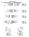
- the fluid is at a higher pressure and is contained within expansion space 22 , as depicted in Figure 1c .
- the volume of expansion space 22 increases as heat is drawn in from outside engine 10 , thereby converting heat to work.
- heat is provided to the fluid in expansion space 22 by means of a heater 64 (shown in Fig. 2 ) which is discussed in greater detail in the description below.
- the hot fluid fills the full expansion space 22 as depicted in Figure 1d .
- the fluid is transferred from expansion space 22 to compression space 24, heating regenerator 26 as the fluid passes through it.
- the fluid is in compression space 24, as depicted in Figure 1a , and is ready for a repetition of the compression phase.
- the Stirling cycle is depicted in a P-V (pressure-volume) diagram as shown in Figure 1e and in a T-S (temperature-entropy) diagram as shown in Figure 1f .
- the Stirling cycle is a closed cycle in that the working fluid is typically not replaced during the course of the cycle.
- US 4,364,724 describes a method and apparatus for closing the air-fuel mixture in a burner.
- the gas concentration in the exhaust gas product of the burner is measured using a gas composition sensor.
- the gas composition sensor may be an oxygen sensor or a carbon monoxide sensor.
- the air flow rate may be adjusted to obtain a predetermined optimal fuel-air ratio, where the optimal fuel-air ratio is based on at least a temperature of the air injected into the combustion chamber of the burner.
- the temperature of the air may be measured using a temperature sensor.
- the temperature of the air is determined based at least on a temperature of the heater head.
- the gas composition sensor is a carbon monoxide sensor and the air flow rate into the burner is adjusted to minimize the gas concentration signal produced by the carbon monoxide sensor.
- the air flow rate may be adjusted to obtain a gas concentration signal from the carbon monoxide sensor that is below a predetermined value.
- a system for controlling the fuel-air ratio of a burner of an external combustion engine having a heater head in accordance with claim 12.
- the system includes a gas composition sensor for monitoring the gas concentration in the exhaust gas product of the burner.
- the gas composition sensor may be an oxygen sensor or a carbon monoxide sensor.
- the air flow rate may be adjusted to obtain a predetermined optimal fuel-air ratio, where the optimal fuel-air ratio is based on at least a temperature of the air injected into the combustion chamber of the burner.
- the temperature of the air may be measured using a temperature sensor.
- the temperature of the air is determined based at least on a temperature of the heater head.
- the gas composition sensor is a carbon monoxide sensor and the air flow rate into the burner is adjusted to minimize the gas concentration signal produced by the carbon monoxide sensor.
- the air flow rate may be adjusted to obtain a gas concentration signal from the carbon monoxide sensor that is below a predetermined value.
- Stirling cycle engine 28 one embodiment of a Stirling cycle engine is shown in cross-section and is designated generally by numeral 28 . While the invention will be described generally with reference to the Stirling engine shown in Figure 2 , it is to be understood that many engines and other fuel burning boilers, furnaces, and machines may similarly benefit from various embodiments and improvements which are subjects of the present invention.
- the configuration of Stirling engine 28 shown in Figure 2 is referred to as an alpha configuration, characterized in that compression piston 30 and expansion piston 32 undergo linear motion within respective and distinct cylinders: compression piston 30 in compression cylinder 34 and expansion piston 32 in expansion cylinder 36.
- the alpha configuration is discussed by way of example only, and without limitation of the scope of any appended claims.
- the main components of Stirling engine 28 include heater 64 , regenerator 66 , and cooler 68 .
- Compression piston 30 and expansion piston 32 are constrained to move in reciprocating linear motion within respective volumes 38 and 40 .
- a cylinder liner 42 may line the respective cylinder surfaces.
- the volumes of the cylinder interior proximate to the heater 64 and cooler 68 will be referred to, herein, as hot and cold sections, respectively, of engine 28.
- the relative phase (the "phase angle") of the reciprocating linear motion of compression piston 30 and expansion piston 32 is governed by their respective coupling to drive mechanism 44 housed in crankcase 46.
- Drive mechanism 44 may be employed to govern the relative timing of pistons and to interconvert linear and rotary motion.
- Compression piston 30 and expansion piston 32 are coupled, respectively, to drive mechanism 44 via a first connecting rod 48 and a second connecting rod 50.
- the volume 38 of compression cylinder 34 is coupled to cooler 68 via duct 45 to allow cyclic cooling of working fluid.
- Duct 45 more particularly, couples compression volume 38 to the annular heat exchangers comprising cooler 68, regenerator 66, and heater 64.
- Expansion cylinder 36 contains a working fluid, preferably helium, which is heated by hot gases generated by a burner (not shown) by conduction through a heater head 52.
- heater head may include a heat exchanger (not shown).
- the heat exchanger may be, for example, heating loops.
- pins or fins are used on the heater head surface to increase the heat transfer across the heater head. The use and method of manufacture of heat transfer pins is described in copending U.S. Patent Application Serial No. 09/115,381, filed July 14,1998 and copending U.S. Patent Application No. 09/517,245, filed March 2, 2000 , which are herein incorporated by reference.
- Stirling engines are capable of providing high thermal efficiency and low emission of pollutants, these objectives impose requirements of thermal efficiency, in particular, on a burner 406 employed to heat heater head 408 of the Stirling engine as shown in Figure 4 .
- Components of such thermal efficiency include the efficient pumping of oxidant (typically, air, and, referred to herein and in any appended claims, without limitation, as "air”) through the burner 406 to provide combustion, and the recovery of hot exhaust leaving the heater head 408.
- oxidant typically, air, and, referred to herein and in any appended claims, without limitation, as "air
- air or other oxidant
- a heat exchanger may be used to transfer heat from the exhaust gases to the combustion air prior to introduction into the burner.
- a pre-heater 412 allows for the exchange of heat from the exhaust gases to the air taken from the ambient environment, typically from an air pump or blower.
- the burner In order to achieve high efficiency and low emissions, the burner must provide substantially complete combustion. In order to achieve substantially complete combustion, a measured amount of air as well as a gaseous fuel, such as propane, are delivered to the burner. Other gaseous fuels include natural gas, methane, butane, liquefied petroleum gas (LPG), producer gas, wood-gas and vaporized liquid fuels such as methanol and ethanol.
- LPG liquefied petroleum gas
- the fuel and air flow rates are controlled in order to allow for ignition of a flame in the burner, for clean emissions after ignition and to provide thermal power to the Stirling engine.
- the fuel and air must also be well-mixed with sufficient amounts of oxygen to limit the emission of carbon monoxide (CO) and hydrocarbons and, additionally, must be burned at low enough flame temperatures to limit the formation of oxides of nitrogen (NO x ).
- CO carbon monoxide
- NO x oxides of nitrogen
- auto-ignition temperature is defined as the temperature at which a fuel will ignite without a temperature-decreasing catalyst under existing conditions of air and fuel pressure.
- the typical preheated air temperature exceeds the auto-ignition temperature of most fuels, potentially causing the fuel-air mixture to ignite before entering the combustion chamber.
- One solution to this problem is to use a non-premixed diffusion flame. However, since such diffusion flames are not well-mixed, higher than desirable emissions of CO and NO x result.
- low emissions and high efficiency may be provided by producing a pre-mixed flame even in the presence of air heated above the auto-ignition temperature of the fuel, and, additionally, by minimizing the pressure drop between the air inlet and the flame region, thereby minimizing blower power consumption.
- flame speed is defined as the speed at which a flame front will propagate through a particular fuel-air mixture.
- combustion axis shall refer to the direction of predominant fluid flow upon combustion of the fluid.
- an intake manifold 399 is shown for application to a Stirling cycle engine or other combustion application in accordance with an embodiment of the present invention.
- the preferred intake manifold and burner described herein are discussed by way of example only, and without limitation of the scope of any of the appended claims.
- Various other methods for building a pre-mix burner are known in the art.
- fuel is pre-mixed with air that may be heated above the fuel's auto-ignition temperature and a flame is prevented from forming until the fuel and air are well-mixed and in the combustion chamber 409 (shown in Fig. 4 ).
- Figure 3a shows a preferred embodiment of the apparatus including an intake manifold 399 and a combustion chamber 310 .
- the intake manifold 399 has an axisymmetrical conduit 301 with an inlet manifold 303 for receiving air 300 supplied via the blower 328 .
- Air 300 is pre-heated to a temperature, typically above 1000 K, which may be above the auto-ignition temperature of the fuel.
- Conduit 301 conveys air 300 flowing inward radially with respect to combustion axis 320 to a swirler 302 disposed within the conduit 301 .
- FIG. 3b shows a cross sectional view of the conduit 301 including swirler 302 in accordance with an embodiment of the invention.
- swirler 302 has several spiral-shaped vanes 330 for directing the flow of air 300 radially inward and imparting a rotational component on the air.
- the diameter of the swirler section of the conduit decreases from the inlet 332 to the outlet 334 of swirler 302 as defined by the length of swirler vanes 330 .
- the decrease in diameter of swirler vanes 330 increases the flow rate of air 300 in substantially inverse proportion to the diameter. The flow rate is increased so that it is above the flame speed of the fuel.
- a gaseous fuel 306 which in a preferred embodiment is propane, is injected into the inwardly flowing air.
- fuel 306 is injected by fuel injector 304 through a series of nozzles 336 as shown in Figure 3c .
- Figure 3c shows a cross sectional view of conduit 301 and includes the fuel jet nozzles 336 .
- Each of the nozzles 336 is positioned at the exit of the swirler vanes 330 and is centralized between two adjacent vanes. Nozzles 336 are positioned in this way for increasing the efficiency of mixing the air and fuel.
- the fuel jet nozzles 336 are sized to provide jets of fuel that extend at least half way across the conduit 301 (shown in Figures 3a and 3b ).
- Nozzles 336 simultaneously inject the fuel 306 across the air flow 300 . Since the air flow is faster than the flame speed, a flame will not form at that point even though the temperature of the air and fuel mixture is above the fuel's auto-ignition temperature. In a preferred embodiment, where propane is used, the preheat temperature, as governed by the temperature of the heater head, is approximately 900 K.
- Fuel 306 is supplied via fuel regulator 324 .
- Throat 308 has an inner radius 314 and an outer dimension 316 .
- the transition of the air-fuel mixture is from a direction that is substantially transverse and radially inward with respect to combustion axis 320 to a direction that is substantially parallel to the combustion axis.
- the contour of the fairing 322 of throat 308 has the shape of an inverted bell such that the cross sectional area of throat 308 with respect to the average flow path remains constant from the inlet 311 of the throat to outlet 312 of the throat.
- the contour is smooth without steps and maintains the flow speed from the outlet of the swirler to the outlet of the throat 308 to avoid separation and the resulting recirculation along any of the surfaces.
- the constant cross sectional area allows the air and fuel to continue to mix without decreasing the flow speed or causing a pressure drop.
- a smooth and constant cross section produces an efficient swirler, where swirler efficiency refers to the fraction of static pressure drop across the swirler that is converted to swirling flow dynamic pressure. Swirl efficiencies of better than 80% may typically be achieved by practice of the invention. Thus, the parasitic power drain of the combustion air fan may be minimized.
- Outlet 312 of the throat flares outward allowing the air-fuel mixture 309 to disperse into the chamber 310 slowing the air-fuel mixture 309 below its flame speed thereby localizing and containing the flame.
- the rotational momentum generated by the swirler 302 produces a flame stabilizing ring vortex as well known in the art.
- burner controller 326 is used to control the fuel and air flow rates provided by fuel regulator 324 and blower 328 respectively.
- the fuel regulator 324 is set to an initial value for ignition.
- the burner controller 326 varies the fuel flow rate to control the heater head temperature as measured by a head temperature sensor 404 (shown in Figure 4 ).
- a flame is proved when a flame detector detects the presence of the flame.
- flame detectors There are several types of flame detectors including thermocouples and ultraviolet sensors known in the art. Flame detection methods are discussed in copending U.S. Patent application Serial No. 09/527,808, filed March 2, 2000 , which is herein incorporated by reference.
- the output (or air mass flow rate) of the combustion air blower 328 is set by the burner controller 326 to control the fuel-air ratio in the combustion chamber 409 (shown in Figure 4 ).
- the fuel-air ratio is the ratio of the fuel mass flow rate to the air mass flow rate and is a primary factor affecting emissions.
- the blower 328 controls the fuel-air ratio by increasing or decreasing the air mass flow rate relative to the fuel mass flow rate. For example, in order to hold the fuel-air ratio constant, the burner controller 326 will increase the blower output as the fuel regulator 324 increases its output and vice versa.
- the desired fuel-air ratio and the fuel flow rate may be changing at the same time, so the burner controller 326 will change the output of the blower 328 to accommodate both the change in desired fuel-air ratio and the fuel flow rate.
- a lean fuel-air mixture has more air than a stoichiometric mixture (i.e., 15.67 grams of air per gram of fuel, if propane is used, for example).
- a stoichiometric mixture i.e., 15.67 grams of air per gram of fuel, if propane is used, for example.
- the emissions of CO, HC and NO x will decrease until the fraction of air in the fuel-air mixture is large enough that the flame becomes unstable. At this point, pockets of the fuel-air mixture will pass through the burner without complete combustion. Incomplete combustion of the fuel-air mixture produces large amounts of CO and HC.
- the CO and HC emissions will quickly increase as more air is added to the fuel-air mixture until the flame extinguishes at a Lean Blow-Out limit ("LBO").
- LBO Lean Blow-Out limit
- the LBO will increase as the temperature of the incoming air (i.e., the preheated air) increases.
- the optimal fuel-air ratio of the fuel-air mixture decreases as the temperature of the preheated air increases during the warmup phase of the Stirling engine. Once the engine is warmed up, the fuel-air ratio is held at or below the optimal fuel-air ratio for operation of the engine.
- the fuel-air ratio must first be controlled to provide the optimal fuel-air ratio for ignition. Once the flame is proved, the fuel-air ratio is controlled to minimize emissions based upon the temperature of the preheated air and the fuel type. When the fuel flow rate is increased or decreased to adjust the temperature of the heater head, the air flow rate is also adjusted to maintain the desired fuel-air ratio.
- a given fuel will only ignite over a limited range of fuel-air ratios.
- an ignition fuel-air ratio is chosen which is slightly above or below the stoichiometric fuel-air ratio corresponding to the fuel being used.
- use of a lean fuel-air mixture minimizes the emissions of carbon monoxide (CO), hydrocarbons (HC) and oxides of nitrogen (NO x ).
- CO carbon monoxide
- HC hydrocarbons
- NO x oxides of nitrogen
- FIG. 5a is a schematic block diagram showing a system for control of the fuel and air provided to a burner in accordance with an embodiment of the invention.
- a burner 502 is coupled to a blower 528 and a fuel source 504 .
- a burner controller 526 is used to control the fuel and air provided to the burner 502 .
- burner 502 may include an intake manifold used to pre-mix the fuel from the fuel source 504 and the air from the blower 528 to form a fuel-air mixture.
- a choked state is achieved by specifying, using the burner controller 526, an initial relatively rich ignition fuel-air ratio that is used to light the premixed fuel-air mixture. Once a flame is established, the ignition fuel-air ratio is then adjusted to a leaner fuel-air ratio using metering valve 510 to reduce the fuel flow.
- Metering valve 510 may be a fast acting metering valve generally known in the art. The adjustment of the fuel-air ratio from a rich mixture to a lean mixture is done over a short period of time (e.g., a fraction of a second) in order to help stabilize the flame.
- FIG. 5b illustrates an exemplary ignition fuel-air equivalence ratio over time used to ignite a fuel-air mixture in accordance with an embodiment of the invention.
- a fuel-air equivalence ratio is plotted versus time.
- the term fuel-air equivalence ratio is well known in the art and is the fuel-air ratio (as defined above) normalized to a stoichiometric fuel-air ratio.
- the behavior of the fuel-air equivalence ratio and the fuel-air ratio are similar and the following discussion will refer to the fuel-air ratio.
- the ignition fuel-air ratio of the fuel-air mixture is initially set to a relatively rich mixture.
- the initial fuel-air mixture is set to 0.9 grams fuel per gram of air.
- the fuel flow from fuel source 504 shown in Figure 5a
- a constant air flow rate is maintained by blower 528 (shown in Figure 5a ) in order to reduce 514 the fuel-air ratio.
- the fuel-air ratio is reduced to 0.7 grams fuel per gram of air.
- a fast acting metering valve 510 may be used to reduce the fuel flow. The flame will generally stabilize 516 at the leaner fuel-air ratio.
- burner controller 526 may implement an adaptive process to locate an appropriate fuel-air ratio for ignition of the fuel-air mixture in the burner.
- Figure 6 illustrates graphically an alternating stepwise sequence of ignition fuel-air equivalence ratios that may be used by a burner controller to light a fuel-air mixture.
- the fuel-air equivalence ratio is the fuel-air ratio normalized to a stoichiometric fuel air ratio.
- the burner controller stores the last ignition fuel air ratio that was used to successfully light the fuel air mixture. This historical ignition fuel-air ratio value may then be used during subsequent lighting attempts.
- the burner controller uses the stored ignition fuel air ratio 602 in its first attempt to light the fuel-air mixture. If the first attempt fails, the ignition fuel air ratio is lowered to a second ignition fuel-air ratio 604 .
- the burner is purged of the unburned fuel-air mixture before adjusting the fuel-air ratio.
- the ignition fuel-air ratio may be adjusted by either changing the fuel flow or changing the air flow. Preferably, the amount of air supplied to the burner is changed because the blower typically provides for a finer adjustment.
- the second ignition fuel-air ratio is stored by the burner controller to use in future attempts to light or re-light the fuel-air mixture in the burner. If the second ignition fuel-air ratio 604 fails, the burner controller will then increase the ignition fuel-air ratio to a third ignition fuel-air ratio 606 that is higher than the first 602 or second 604 ignition fuel-air ratios. As mentioned above, the burner may be purged of the unburned fuel-air mixture before adjusting the fuel-air ratio. If the fuel-air mixture is successfully ignited at the third ignition fuel-air ratio, the third ignition fuel-air ratio 606 is stored by the burner controller for use as a starting point for future attempts to light the fuel-air mixture.
- the process continues and the ignition fuel-air ratio is again lowered to a fourth ignition fuel-air ratio 608 .
- the fourth ignition fuel-air ratio 608 is lower than both the first 602 and second 604 ignition fuel air ratios.
- the sequence of ignition fuel-air ratios is repeated until the fuel-air mixture in the burner successfully ignites.
- the value of the ignition fuel-air ratio at which the fuel-air mixture ignites is then stored (and replaces any previously stored value) by the burner controller for the next attempt at lighting or re-lighting the fuel-air mixture. This process allows the burner system to adapt to component degradation and other changes.
- the lighting behavior of the fuel-air mixture in the burner may also be affected by changes in the flammability limits for the fuel caused by the preheated air temperature. At higher preheated air temperatures, a leaner fuel-air mixture will light more easily and still achieve a stable flame. Accordingly, the ignition fuel air ratio, as determined, for example, by the methods described above, may be adjusted or offset based on the preheated air temperature in order to ensure proper lighting. As discussed above, use of a lean fuel-air mixture minimizes emissions of carbon monoxide (CO), hydrocarbons (HC) and oxides of nitrogen (NO x ).
- CO carbon monoxide
- HC hydrocarbons
- NO x oxides of nitrogen
- the temperature of the preheated air is preferably measured using a temperature sensor, such as a thermocouple 410 , in an air swirler 402 coupled to the combustion chamber 409 as shown in Figure 4 .
- the measured preheated air temperature may then used to determine an appropriate offset to the ignition fuel-air ratio based on a predetermined relationship between the preheated air temperature and the fuel-air ratio for ignition.
- a leaner fuel-air mixture may be used at higher preheated air temperatures. Therefore, in one embodiment, at a high preheated air temperature, the ignition fuel-air ratio will be lowered to a leaner ignition fuel-air ratio.
- the ignition fuel-air ratio is maintained until the flame stabilizes and the temperature of the interior of the combustion chamber increases to a warm-up temperature.
- the temperature of the combustion chamber 409 is typically determined by measuring the temperature of the heater head 408 or by allowing a predetermined time interval for the combustion chamber to heat.
- a temperature sensor such as thermocouple 404 , may be used to measure the temperature of heater head 408 .
- the ignition fuel-air ratio is held until the heater head temperature reaches 300°C and the flame has been lit for 5 seconds.
- the fuel-air ratio is then controlled based upon the air preheat temperature and the fuel type.
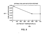
- the optimal fuel-air ratio 801 of the fuel-air mixture decreases as the temperature of the preheated air 803 increases as shown in Figure 8 .
- the temperature of the preheated air is preferably measured using a high temperature sensor that is placed in the incoming air stream just before the fuel is added to the preheated air.
- a temperature sensor 410 may be placed in the air swirler 402 to measure the temperature of the preheated air.
- the temperature of the preheated air may be inferred from the heater head temperature.
- the preheated air temperature may be estimated from the measured heater head temperature and a mathematical thermal model of the heater head, burner and preheater.
- Such a model may be based on an electrical analogue of capacitors and resistors as shown in Figure 7.
- Figure 7 illustrates an electrical model of the thermal behavior of the heater head and pre-heater in accordance with an embodiment of the invention. It is well known in the art to represent thermal systems using electrical analogues.
- the mathematical model, as shown in Figure 7 may be used by the burner controller to estimate the preheated air temperature based on the measured heater head temperature.
- the thermal power produced by the burner is represented by the current source 710 .
- V head is the known heater head temperature.
- a temperature sensor such as a thermocouple 404 shown in Figure 4 , may be used to measure the temperature of the heater head.
- the preheated air temperature is approximately the temperature of the pre-heater, V preheater .
- Capacitor 702 represents the thermal capacitance of the heater head and capacitor 704 represents the thermal capacitance of the pre-heater.
- Resistor 706 represents the thermal resistance between the combustion gases leaving the heater head and the pre-heater.
- Resistor 708 represents the thermal resistance between the pre-heater and the incoming preheated air.
- the preheated air temperature may be approximated by subtracting several hundred degrees Celsius from the heater head temperature. In one embodiment, the preheated air temperature is taken as the heater head temperature minus 300°C.
- the optimal fuel-air ratio will first decrease linearly with the preheated air temperature from a "start" fuel-air ratio for room temperature air to a "run” fuel air ratio, for a warmed up preheated air temperature.
- the air is considered fully warmed up when it exceeds the known auto-ignition temperature for the fuel.
- the auto-ignition temperature for propane is 490°C.
- the "start" fuel-air ratio is 0.052 grams of fuel to grams of air, which results in approximately 4% oxygen in the exhaust of the Stirling engine.
- the "run” fuel-air ratio in the preferred embodiment is 0.026 grams of fuel to grams of air, which results in approximately 13% oxygen in the exhaust of the Stirling engine.
- the determination of the fuel-air ratio may be based on a measurement of the oxygen content in the exhaust of the Stirling engine.
- a gas sensor 902 may be placed in the path of the exhaust gasses from combustion chamber 310 (as shown in Figure 3a ) to sample the exhaust gas and measure the percentage of a particular gas present in the exhaust.
- the gas sensor 902 is an oxygen sensor and is used to measure the percentage of oxygen in the exhaust.
- Oxygen sensors 902 such as those based on zirconium-oxide, may be used to measure the oxygen level.
- Figure 10 shows the relationship between the fuel-air equivalence ratio and the percentage of exhaust oxygen, and between the fuel-air equivalence ratio and the signal of an oxygen sensor, such as a zirconium-oxide sensor.
- the gas sensor 902 after measuring the exhaust oxygen level, the gas sensor 902 provides a signal 904 to the burner controller (or fuel-air controller) 910 which outputs a blower signal 908 to the blower 912 .
- the air provided by blower 912 is then mixed with fuel provided by a fuel regulator 916 from a fuel source 914 to form a fuel-air mixture 918 .
- the gas sensor signal will be proportional to the oxygen present in the exhaust as shown by curve 1002 in Figure 10 . If the air-flow drops low enough, however, there will be no oxygen in the exhaust.
- the gas sensor responds to the carbon monoxide (CO) instead of the oxygen.
- CO carbon monoxide
- the gas sensor signal will be proportional to the fuel-air equivalence ratio as shown by curve 1004 in Figure 10 .
- the sensor response may be used to determine the fuel-air ratio and provide good fuel-air control in both fuel rich and lean conditions.
- the actual fuel-air ratio can be determined from the magnitude of the oxygen sensor signal and the sign of the derivative of the oxygen signal versus the blower signal.
- a negative derivative indicates that the burner is operating in the fuel rich region while a positive derivative indicates that the burner is operating in the fuel lean or oxygen rich region.
- the fuel-air controller 910 (shown in Figure 9 ) adjusts the speed of the blower 912 , faster or slower, depending on which region the burner 906 is operating in, so that the optimal fuel-air ratio is achieved.
- the fuel-air ratio may be based on a measurement of the carbon monoxide (CO) content in the exhaust of the Stirling engine using a carbon monoxide sensor as the gas sensor 902 (shown in Figure 9 ).
- CO sensors are advantageous for reasons of cost.
- the fuel-air ratio can be expressed in terms of the CO exhaust signal in a piece-wise linear fashion as shown in Figure 11.
- Figure 11 shows the fuel-air equivalence ratio versus the CO exhaust signal. The relationship is non-monotonic, meaning that for a given CO value or Co sensor signal, there are two possible fuel-air ratio values.
- the fuel-air equivalence ratio may be determined from the magnitude of the CO sensor signal and the derivative of CO signal versus the blower signal.
- the controller 910 uses the blower signal 908 and the CO signal 904 from the CO sensor 902 to determine the current fuel-air ratio, compare it to the desired (or optimal) fuel-air ratio and drive the blower 912 to create the desired (or optimal) fuel-air ratio.
- the controller 910 may use a number of strategies to control the fuel-air ratio based on a CO sensor. In one embodiment, the controller 910 adjusts the speed of blower 912 , faster or slower, to produce the desired (or optimal) fuel-air ratio. In an alternative embodiment, the controller 910 may vary the blower speed to minimize the CO signal. Optimal control algorithms used to seek a minimal signal are well known in the art. In a further embodiment, the controller 910 may control the fuel and air delivered to the burner to hold the CO signal below a predetermined amount. The fuel-air ratio would be allowed to fluctuate as long as the CO level remained below the desired level.
- the systems and methods described herein apply for all gaseous fuels, including but not limited to, propane, natural gas, methane, butane, liquefied petroleum gas (LPG), producer gas, wood-gas and vaporized liquid fuels such as methanol and ethanol.
- LPG liquefied petroleum gas
- producer gas wood-gas and vaporized liquid fuels such as methanol and ethanol.
- vaporized liquid fuels such as methanol and ethanol.
- the systems and methods described herein may be applied in other applications besides the Stirling engine in terms of which the invention has been described.
- the described embodiments of the invention are intended to be merely exemplary and numerous variations and modifications will be apparent to those skilled in the art. All such variations and modifications are intended to be within the scope of the present invention as defined in the appended claims.
Landscapes
- Engineering & Computer Science (AREA)
- General Engineering & Computer Science (AREA)
- Mechanical Engineering (AREA)
- Chemical & Material Sciences (AREA)
- Combustion & Propulsion (AREA)
- Regulation And Control Of Combustion (AREA)
Claims (22)
- Procédé pour commander le rapport carburant/air d'un brûleur (406, 502) d'un moteur à combustion externe, comprenant une tête de chauffage (408), le brûleur comprenant un ventilateur (328, 528, 912), le procédé étant basé au moins sur la concentration d'un gaz dans un produit de gaz d'échappement d'une chambre de combustion du brûleur, le procédé comprenant les opérations consistant à :mesurer la concentration en gaz dans le produit de gaz d'échappement ;dériver un signal de concentration de gaz depuis la concentration de gaz mesurée ; etdéterminer le rapport carburant/air à partir du signal de concentration de gaz et du signe de la dérivée du signal de concentration de gaz par rapport au signal de pilotage du ventilateur ;caractérisé en ce que le ventilateur (328) réagit à un signal de pilotage de ventilateur pour injecter de l'air dans le brûleur, et en commandant le rapport carburant/air par ajustement d'un débit d'air entrant dans le brûleur, en ajustant le signal de pilotage du ventilateur.
- Procédé selon la revendication 1, dans lequel la mesure de la concentration de gaz dans les produits de gaz d'échappement comprend d'utiliser un capteur de composition gazeuse (902).
- Procédé selon la revendication 2, dans lequel l'utilisation d'un capteur de composition gazeuse (902) comprend d'utiliser au moins un capteur parmi un capteur d'oxygène et un capteur de monoxyde de carbone.
- Procédé selon la revendication 1, dans lequel la mesure de la concentration de gaz dans le produit de gaz d'échappement comprend de mesurer au moins un composant parmi l'oxygène et le monoxyde de carbone.
- Procédé selon la revendication 1, dans lequel le moteur à combustion externe est un moteur à cycle de Stirling.
- Procédé selon la revendication 1, dans lequel le débit d'air entrant dans le brûleur (406, 502) est ajusté pour obtenir un rapport carburant/air optimal prédéterminé.
- Procédé selon la revendication 6, dans lequel le rapport carburant/air optimal est basé au moins sur une température de l'air injecté dans la chambre de combustion du brûleur par le ventilateur.
- Procédé selon la revendication 7, dans lequel la température de l'air est mesurée en utilisant un capteur de température (410) placé dans un trajet de l'air injecté dans la chambre de combustion du brûleur par le ventilateur.
- Procédé selon la revendication 7, dans lequel la température de l'air est déterminée en se basant au moins sur une température de la tête de chauffage.
- Procédé selon la revendication 3, dans lequel le capteur de composition gazeuse (902) est un capteur de monoxyde de carbone (902) et le débit d'air entrant dans le brûleur est ajusté pour minimiser le signal de concentration gazeuse produit par le capteur de monoxyde de carbone.
- Procédé selon la revendication 3, dans lequel le capteur de composition gazeuse (902) est un capteur de monoxyde de carbone, et en ce que le débit d'air entrant dans le brûleur est ajusté pour obtenir un signal de concentration gazeuse provenant du capteur de monoxyde de carbone qui est au-dessous d'une valeur prédéterminée.
- Système pour commander le rapport carburant/air d'un brûleur d'un moteur à combustion externe ayant une tête de chauffage, basé au moins sur la concentration d'un gaz dans un produit de gaz d'échappement d'une chambre de combustion du brûleur, le système comprenant :un capteur (902) pour mesurer la concentration gazeuse dans le produit de gaz d'échappement de la chambre de combustion et pour générer un signal de capteur ;un ventilateur (378, 528, 912) pour injecter de l'air dans le brûleur ; etun contrôleur (910) pour recevoir le signal de capteur provenant du capteur ;caractérisé en ce que le ventilateur est régi par un signal de pilotage de ventilateur, et
le contrôleur (910) est agencé pour ajuster le signal de pilotage de ventilateur en se basant au moins sur le signal de capteur provenant du capteur et sur le signe de la dérivée du signal de capteur par rapport au signal de pilotage de ventilateur, pour commander le rapport carburant/air dans le brûleur. - Système selon la revendication 12, dans lequel le capteur (902) est un capteur de composition gazeuse.
- Système selon la revendication 13, dans lequel le capteur de composition gazeuse (902) est au moins un capteur parmi un capteur d'oxygène et un capteur de monoxyde de carbone.
- Système selon la revendication 12, dans lequel le capteur (902) mesure la concentration gazeuse d'un produit au moins parmi l'oxygène et le monoxyde de carbone.
- Système selon la revendication 12, dans lequel le moteur à combustion externe inclut un moteur à cycle de Stirling.
- Système selon la revendication 12, dans lequel le rapport carburant/air dans le brûleur (406, 502) est commandé pour obtenir un rapport carburant/air optimal prédéterminé.
- Système selon la revendication 17, dans lequel le rapport carburant/air optimal est basé au moins sur une température de l'air injecté dans la chambre de combustion du brûleur par le ventilateur.
- Système selon la revendication 18, dans lequel la température de l'air est mesurée en utilisant un capteur de température placé dans un trajet de l'air injecté dans la chambre de combustion du brûleur par le ventilateur.
- Système selon la revendication 18, dans lequel la température de l'air est déterminée en se basant au moins sur une température de la tête de chauffage.
- Système selon la revendication 14, dans lequel le capteur de composition gazeuse (902) est un capteur de monoxyde de carbone et le signal de pilotage du ventilateur est ajusté pour minimiser le signal de capteur produit par le capteur de monoxyde de carbone.
- Système selon la revendication 14, dans lequel le capteur de composition gazeuse (902) est un capteur de monoxyde de carbone, et le signal de pilotage du ventilateur est ajusté pour obtenir un signal de concentration gazeuse depuis le capteur de monoxyde de carbone qui est au-dessous d'une valeur prédéterminée.
Applications Claiming Priority (3)
| Application Number | Priority Date | Filing Date | Title |
|---|---|---|---|
| US853239 | 1992-03-18 | ||
| US09/853,239 US6705081B2 (en) | 1997-07-15 | 2001-05-11 | System and method for sensor control of the fuel-air ratio in a burner |
| PCT/US2002/014771 WO2002092987A2 (fr) | 2001-05-11 | 2002-05-10 | Systeme et procede de commande de capteurs du rapport carburant-air dans un bruleur |
Publications (2)
| Publication Number | Publication Date |
|---|---|
| EP1392959A2 EP1392959A2 (fr) | 2004-03-03 |
| EP1392959B1 true EP1392959B1 (fr) | 2008-10-15 |
Family
ID=25315469
Family Applications (1)
| Application Number | Title | Priority Date | Filing Date |
|---|---|---|---|
| EP02769703A Expired - Lifetime EP1392959B1 (fr) | 2001-05-11 | 2002-05-10 | Systeme et procede de commande de capteurs du rapport carburant-air dans un bruleur |
Country Status (9)
| Country | Link |
|---|---|
| US (1) | US6705081B2 (fr) |
| EP (1) | EP1392959B1 (fr) |
| JP (1) | JP4233877B2 (fr) |
| AT (1) | ATE411460T1 (fr) |
| AU (1) | AU2002344327B2 (fr) |
| CA (2) | CA2446855C (fr) |
| DE (1) | DE60229381D1 (fr) |
| MX (1) | MXPA03010292A (fr) |
| WO (1) | WO2002092987A2 (fr) |
Families Citing this family (31)
| Publication number | Priority date | Publication date | Assignee | Title |
|---|---|---|---|---|
| US7111460B2 (en) * | 2000-03-02 | 2006-09-26 | New Power Concepts Llc | Metering fuel pump |
| US7313916B2 (en) * | 2002-03-22 | 2008-01-01 | Philip Morris Usa Inc. | Method and apparatus for generating power by combustion of vaporized fuel |
| US7340879B2 (en) | 2002-11-13 | 2008-03-11 | Deka Products Limited Partnership | Locally powered water distillation system |
| US8511105B2 (en) | 2002-11-13 | 2013-08-20 | Deka Products Limited Partnership | Water vending apparatus |
| US8069676B2 (en) | 2002-11-13 | 2011-12-06 | Deka Products Limited Partnership | Water vapor distillation apparatus, method and system |
| WO2005003544A1 (fr) * | 2003-07-01 | 2005-01-13 | Tiax Llc | Echangeurs thermiques a contact pour machines a cycle de stirling |
| GB0328292D0 (en) * | 2003-12-05 | 2004-01-07 | Microgen Energy Ltd | A stirling engine assembly |
| US8502064B2 (en) * | 2003-12-11 | 2013-08-06 | Philip Morris Usa Inc. | Hybrid system for generating power |
| US7337057B2 (en) * | 2004-05-28 | 2008-02-26 | General Electric Company | Methods and apparatus for predicting and/or for avoiding lean blow-outs |
| CA2550607A1 (fr) * | 2004-07-29 | 2006-02-02 | Guangzhou Light Holdings Limited | Four a rotir multifonctions |
| US7461509B2 (en) * | 2005-05-06 | 2008-12-09 | General Electric Company | Method and system for determining lean blow out condition for gas turbine combustion cans |
| US20070044468A1 (en) * | 2005-09-01 | 2007-03-01 | Stm Power, Inc. | Energy recovery system for combustible vapors |
| US11826681B2 (en) | 2006-06-30 | 2023-11-28 | Deka Products Limited Partneship | Water vapor distillation apparatus, method and system |
| US8505323B2 (en) | 2007-06-07 | 2013-08-13 | Deka Products Limited Partnership | Water vapor distillation apparatus, method and system |
| US11884555B2 (en) | 2007-06-07 | 2024-01-30 | Deka Products Limited Partnership | Water vapor distillation apparatus, method and system |
| US8006511B2 (en) | 2007-06-07 | 2011-08-30 | Deka Products Limited Partnership | Water vapor distillation apparatus, method and system |
| US8359877B2 (en) * | 2008-08-15 | 2013-01-29 | Deka Products Limited Partnership | Water vending apparatus |
| EP2708724B1 (fr) * | 2011-05-11 | 2017-04-19 | Toyota Jidosha Kabushiki Kaisha | Dispositif de commande pour moteur à combustion interne |
| US20140034475A1 (en) | 2012-04-06 | 2014-02-06 | Deka Products Limited Partnership | Water Vapor Distillation Apparatus, Method and System |
| WO2014018896A1 (fr) | 2012-07-27 | 2014-01-30 | Deka Products Limited Partnership | Commande de la conductivité dans une sortie d'eau de production destinée à un évaporateur |
| US9482432B2 (en) | 2012-09-26 | 2016-11-01 | United Technologies Corporation | Gas turbine engine combustor with integrated combustor vane having swirler |
| US9404654B2 (en) | 2012-09-26 | 2016-08-02 | United Technologies Corporation | Gas turbine engine combustor with integrated combustor vane |
| US9335050B2 (en) | 2012-09-26 | 2016-05-10 | United Technologies Corporation | Gas turbine engine combustor |
| EP3147566B1 (fr) * | 2015-09-22 | 2020-05-06 | Electrolux Appliances Aktiebolag | Système de brûleur à gaz pour une cuisinière à gaz avec un thermocouple et procédé pour déterminer si un ustensile de cuisson est placé sur le brûleur à gaz. |
| US10047679B2 (en) * | 2016-06-14 | 2018-08-14 | General Electric Company | System and method to enhance lean blowout monitoring |
| US11092335B2 (en) * | 2018-01-23 | 2021-08-17 | Rheem Manufacturing Company | Ignition control systems for fuel-fired devices |
| CN112097399A (zh) * | 2019-06-18 | 2020-12-18 | 华帝股份有限公司 | 一种防止燃气热水器爆燃的控制方法及燃气热水器 |
| US11486576B2 (en) * | 2019-08-23 | 2022-11-01 | Regal Beloit America, Inc. | System and method for burner ignition using sensorless constant mass flow draft inducers |
| CA3158759A1 (fr) * | 2019-11-22 | 2021-05-27 | Elavo Energy Solutions Ltd. | Systeme et procede d'elimination de fluide de forage a partir de deblais de forage a l'aide de chaleur directe |
| US20210317987A1 (en) * | 2020-04-10 | 2021-10-14 | Total Destruction Products, LLC | Air assisted enclosed combustion device |
| JP7827551B2 (ja) * | 2022-06-02 | 2026-03-10 | アズビル株式会社 | 燃焼監視装置、及び、燃焼監視プログラム |
Family Cites Families (30)
| Publication number | Priority date | Publication date | Assignee | Title |
|---|---|---|---|---|
| US3775973A (en) | 1970-05-04 | 1973-12-04 | P Hudson | Combustion products pressure generators intermittent burner cycle and engines |
| US3860384A (en) * | 1972-05-25 | 1975-01-14 | Intelcon Rad Tech | Method to control NOX formation in fossil-fueled boiler furnaces |
| US4008039A (en) * | 1975-05-16 | 1977-02-15 | International Harvester Company | Low emission burners and control systems therefor |
| US4067191A (en) | 1975-10-10 | 1978-01-10 | Forenade Fabriksverken | System for supplying fuel and combustion air to an external combustion engine |
| US4085588A (en) | 1976-04-05 | 1978-04-25 | Ford Motor Company | Concentric crossflow recuperator for stirling engine |
| SE439980B (sv) | 1978-06-02 | 1985-07-08 | United Stirling Ab & Co | Forfarande och anordning for reglering av luft/brensleblandning vid brennare av den typ som er utformade med ett evaporatorror |
| US4231222A (en) | 1978-09-18 | 1980-11-04 | Ford Motor Company | Air fuel control system for Stirling engine |
| US4330260A (en) | 1979-01-31 | 1982-05-18 | Jorgensen Lars L S | Method and apparatus for regulating the combustion in a furnace |
| JPS60122255A (ja) | 1983-12-07 | 1985-06-29 | Aisin Seiki Co Ltd | スタ−リング機関の温度制御方法 |
| JPS61128024A (ja) * | 1984-11-26 | 1986-06-16 | Noritsu Co Ltd | 強制通風式燃焼器 |
| JPS61128014A (ja) | 1984-11-28 | 1986-06-16 | Matsushita Electric Ind Co Ltd | 石油燃焼器 |
| JPH0435567Y2 (fr) | 1985-03-20 | 1992-08-24 | ||
| FR2609154A1 (fr) | 1986-12-29 | 1988-07-01 | Pramata | Dispositif de regulation de la combustion, notamment de la teneur en oxygene des fumees de combustion par un bruleur a air souffle, procede de mise en oeuvre et bruleur equipe d'un tel dispositif |
| US4881372A (en) | 1988-02-29 | 1989-11-21 | Aisin Seiki Kabushiki Kaisha | Stirling engine |
| JPH0221123A (ja) | 1988-07-11 | 1990-01-24 | Matsushita Electric Ind Co Ltd | 給湯器の制御装置 |
| JPH0291461A (ja) | 1988-09-29 | 1990-03-30 | Aisin Seiki Co Ltd | スターリングエンジン |
| JPH02256856A (ja) | 1989-03-28 | 1990-10-17 | Mitsubishi Electric Corp | 外燃機関の加熱装置 |
| US4977742A (en) | 1989-04-21 | 1990-12-18 | Stirling Thermal Motors, Inc. | Stirling engine with integrated gas combustor |
| JPH039058A (ja) | 1989-06-01 | 1991-01-16 | Aisin Seiki Co Ltd | スターリングエンジンの燃焼制御装置 |
| US5065579A (en) | 1990-10-12 | 1991-11-19 | Gas Research Institute | Feedback air-fuel control system for Stirling engines |
| JPH04347410A (ja) | 1991-05-24 | 1992-12-02 | Matsushita Electric Ind Co Ltd | 燃焼器の着火制御装置 |
| JP3357384B2 (ja) | 1991-08-27 | 2002-12-16 | マツダ株式会社 | 火花点火式往復動型エンジン |
| US5735681A (en) | 1993-03-19 | 1998-04-07 | The Regents, University Of California | Ultralean low swirl burner |
| JPH0915197A (ja) | 1995-06-26 | 1997-01-17 | Aisin Seiki Co Ltd | 外燃機関用空燃比制御装置 |
| AT406514B (de) | 1997-04-28 | 2000-06-26 | Vaillant Gmbh | Verfahren zur zündung eines gasbeheizten brenners |
| US6247310B1 (en) * | 1997-07-15 | 2001-06-19 | New Power Concepts Llc | System and method for control of fuel and air delivery in a burner of a thermal-cycle engine |
| DE69819730T2 (de) * | 1997-07-15 | 2004-09-30 | New Power Concepts Llc | Brennverfahren |
| US6381958B1 (en) * | 1997-07-15 | 2002-05-07 | New Power Concepts Llc | Stirling engine thermal system improvements |
| US5921764A (en) | 1997-07-18 | 1999-07-13 | Stirling Thermal Motors, Inc. | Heat engine combustor |
| US5954039A (en) | 1998-04-01 | 1999-09-21 | Ford Global Technologies, Inc. | Air/fuel ratio control system |
-
2001
- 2001-05-11 US US09/853,239 patent/US6705081B2/en not_active Expired - Lifetime
-
2002
- 2002-05-10 DE DE60229381T patent/DE60229381D1/de not_active Expired - Lifetime
- 2002-05-10 JP JP2002590229A patent/JP4233877B2/ja not_active Expired - Lifetime
- 2002-05-10 AU AU2002344327A patent/AU2002344327B2/en not_active Ceased
- 2002-05-10 CA CA2446855A patent/CA2446855C/fr not_active Expired - Lifetime
- 2002-05-10 WO PCT/US2002/014771 patent/WO2002092987A2/fr not_active Ceased
- 2002-05-10 CA CA2721197A patent/CA2721197C/fr not_active Expired - Lifetime
- 2002-05-10 EP EP02769703A patent/EP1392959B1/fr not_active Expired - Lifetime
- 2002-05-10 AT AT02769703T patent/ATE411460T1/de not_active IP Right Cessation
- 2002-05-10 MX MXPA03010292A patent/MXPA03010292A/es active IP Right Grant
Also Published As
| Publication number | Publication date |
|---|---|
| WO2002092987A2 (fr) | 2002-11-21 |
| DE60229381D1 (de) | 2008-11-27 |
| US6705081B2 (en) | 2004-03-16 |
| JP4233877B2 (ja) | 2009-03-04 |
| MXPA03010292A (es) | 2004-03-09 |
| WO2002092987A3 (fr) | 2003-07-24 |
| CA2446855A1 (fr) | 2002-11-21 |
| EP1392959A2 (fr) | 2004-03-03 |
| AU2002344327B2 (en) | 2007-11-22 |
| US20010032452A1 (en) | 2001-10-25 |
| CA2721197C (fr) | 2014-01-28 |
| ATE411460T1 (de) | 2008-10-15 |
| CA2721197A1 (fr) | 2002-11-21 |
| CA2446855C (fr) | 2010-12-07 |
| JP2005515339A (ja) | 2005-05-26 |
Similar Documents
| Publication | Publication Date | Title |
|---|---|---|
| AU2002344327B2 (en) | System and method for sensor control of the fuel-air ratio in a burner | |
| AU2002344327A1 (en) | System and method for sensor control of the fuel-air ratio in a burner | |
| AU2001250007B2 (en) | System and method for control of fuel and air delivery in a burner of a thermal-cycle engine | |
| AU2001250007A1 (en) | System and method for control of fuel and air delivery in a burner of a thermal-cycle engine | |
| EP1756475B1 (fr) | Bruleur a combustible gazeux | |
| JP4281610B2 (ja) | 予混合圧縮自着火機関の運転方法及び予混合圧縮自着火機関 | |
| US9249744B2 (en) | Method for operating an engine | |
| CN101365868A (zh) | 内燃机及改进燃烧室的方法 | |
| CN1871414B (zh) | 向气态燃料直喷式内燃机提供高废气再循环的方法与设备 | |
| JP2007224807A (ja) | エンジン | |
| US4546610A (en) | Prevaporizing combustion method | |
| KR101466157B1 (ko) | 예혼합 압축착화 엔진 시스템 | |
| Vozár | After ignition, direct water injection (ai-wdi) dew point based closed loop algorithm logic | |
| WO2020014636A1 (fr) | Systèmes, appareil et procédés pour augmenter la température de combustion de mélanges carburant-air dans des moteurs à combustion interne | |
| JP2000054874A (ja) | 圧縮着火式内燃機関の燃料および燃焼方法 | |
| Pålsson | Development of a LPP CGR combustion system with ultra-low emissions for a SOLO 161 Stirling engine based micro-CHP unit | |
| Lucke et al. | The Heat-Engine Problem |
Legal Events
| Date | Code | Title | Description |
|---|---|---|---|
| PUAI | Public reference made under article 153(3) epc to a published international application that has entered the european phase |
Free format text: ORIGINAL CODE: 0009012 |
|
| 17P | Request for examination filed |
Effective date: 20031211 |
|
| AK | Designated contracting states |
Kind code of ref document: A2 Designated state(s): AT BE CH CY DE DK ES FI FR GB GR IE IT LI LU MC NL PT SE TR |
|
| AX | Request for extension of the european patent |
Extension state: AL LT LV MK RO SI |
|
| 17Q | First examination report despatched |
Effective date: 20061123 |
|
| GRAP | Despatch of communication of intention to grant a patent |
Free format text: ORIGINAL CODE: EPIDOSNIGR1 |
|
| GRAS | Grant fee paid |
Free format text: ORIGINAL CODE: EPIDOSNIGR3 |
|
| GRAA | (expected) grant |
Free format text: ORIGINAL CODE: 0009210 |
|
| AK | Designated contracting states |
Kind code of ref document: B1 Designated state(s): AT BE CH CY DE DK ES FI FR GB GR IE IT LI LU MC NL PT SE TR |
|
| REG | Reference to a national code |
Ref country code: GB Ref legal event code: FG4D Ref country code: CH Ref legal event code: EP |
|
| REG | Reference to a national code |
Ref country code: IE Ref legal event code: FG4D |
|
| REF | Corresponds to: |
Ref document number: 60229381 Country of ref document: DE Date of ref document: 20081127 Kind code of ref document: P |
|
| NLV1 | Nl: lapsed or annulled due to failure to fulfill the requirements of art. 29p and 29m of the patents act | ||
| PG25 | Lapsed in a contracting state [announced via postgrant information from national office to epo] |
Ref country code: ES Free format text: LAPSE BECAUSE OF FAILURE TO SUBMIT A TRANSLATION OF THE DESCRIPTION OR TO PAY THE FEE WITHIN THE PRESCRIBED TIME-LIMIT Effective date: 20090126 Ref country code: AT Free format text: LAPSE BECAUSE OF FAILURE TO SUBMIT A TRANSLATION OF THE DESCRIPTION OR TO PAY THE FEE WITHIN THE PRESCRIBED TIME-LIMIT Effective date: 20081015 |
|
| PG25 | Lapsed in a contracting state [announced via postgrant information from national office to epo] |
Ref country code: NL Free format text: LAPSE BECAUSE OF FAILURE TO SUBMIT A TRANSLATION OF THE DESCRIPTION OR TO PAY THE FEE WITHIN THE PRESCRIBED TIME-LIMIT Effective date: 20081015 Ref country code: PT Free format text: LAPSE BECAUSE OF FAILURE TO SUBMIT A TRANSLATION OF THE DESCRIPTION OR TO PAY THE FEE WITHIN THE PRESCRIBED TIME-LIMIT Effective date: 20090316 Ref country code: FI Free format text: LAPSE BECAUSE OF FAILURE TO SUBMIT A TRANSLATION OF THE DESCRIPTION OR TO PAY THE FEE WITHIN THE PRESCRIBED TIME-LIMIT Effective date: 20081015 |
|
| PG25 | Lapsed in a contracting state [announced via postgrant information from national office to epo] |
Ref country code: BE Free format text: LAPSE BECAUSE OF FAILURE TO SUBMIT A TRANSLATION OF THE DESCRIPTION OR TO PAY THE FEE WITHIN THE PRESCRIBED TIME-LIMIT Effective date: 20081015 Ref country code: DK Free format text: LAPSE BECAUSE OF FAILURE TO SUBMIT A TRANSLATION OF THE DESCRIPTION OR TO PAY THE FEE WITHIN THE PRESCRIBED TIME-LIMIT Effective date: 20081015 |
|
| PLBE | No opposition filed within time limit |
Free format text: ORIGINAL CODE: 0009261 |
|
| STAA | Information on the status of an ep patent application or granted ep patent |
Free format text: STATUS: NO OPPOSITION FILED WITHIN TIME LIMIT |
|
| PG25 | Lapsed in a contracting state [announced via postgrant information from national office to epo] |
Ref country code: IT Free format text: LAPSE BECAUSE OF FAILURE TO SUBMIT A TRANSLATION OF THE DESCRIPTION OR TO PAY THE FEE WITHIN THE PRESCRIBED TIME-LIMIT Effective date: 20081015 Ref country code: SE Free format text: LAPSE BECAUSE OF FAILURE TO SUBMIT A TRANSLATION OF THE DESCRIPTION OR TO PAY THE FEE WITHIN THE PRESCRIBED TIME-LIMIT Effective date: 20090115 |
|
| 26N | No opposition filed |
Effective date: 20090716 |
|
| PG25 | Lapsed in a contracting state [announced via postgrant information from national office to epo] |
Ref country code: MC Free format text: LAPSE BECAUSE OF NON-PAYMENT OF DUE FEES Effective date: 20090531 |
|
| REG | Reference to a national code |
Ref country code: CH Ref legal event code: PL |
|
| PG25 | Lapsed in a contracting state [announced via postgrant information from national office to epo] |
Ref country code: CH Free format text: LAPSE BECAUSE OF NON-PAYMENT OF DUE FEES Effective date: 20090531 Ref country code: LI Free format text: LAPSE BECAUSE OF NON-PAYMENT OF DUE FEES Effective date: 20090531 |
|
| PG25 | Lapsed in a contracting state [announced via postgrant information from national office to epo] |
Ref country code: IE Free format text: LAPSE BECAUSE OF NON-PAYMENT OF DUE FEES Effective date: 20090510 |
|
| PG25 | Lapsed in a contracting state [announced via postgrant information from national office to epo] |
Ref country code: GR Free format text: LAPSE BECAUSE OF FAILURE TO SUBMIT A TRANSLATION OF THE DESCRIPTION OR TO PAY THE FEE WITHIN THE PRESCRIBED TIME-LIMIT Effective date: 20090116 |
|
| PG25 | Lapsed in a contracting state [announced via postgrant information from national office to epo] |
Ref country code: LU Free format text: LAPSE BECAUSE OF NON-PAYMENT OF DUE FEES Effective date: 20090510 |
|
| PG25 | Lapsed in a contracting state [announced via postgrant information from national office to epo] |
Ref country code: TR Free format text: LAPSE BECAUSE OF FAILURE TO SUBMIT A TRANSLATION OF THE DESCRIPTION OR TO PAY THE FEE WITHIN THE PRESCRIBED TIME-LIMIT Effective date: 20081015 |
|
| PG25 | Lapsed in a contracting state [announced via postgrant information from national office to epo] |
Ref country code: CY Free format text: LAPSE BECAUSE OF FAILURE TO SUBMIT A TRANSLATION OF THE DESCRIPTION OR TO PAY THE FEE WITHIN THE PRESCRIBED TIME-LIMIT Effective date: 20081015 |
|
| REG | Reference to a national code |
Ref country code: FR Ref legal event code: PLFP Year of fee payment: 14 |
|
| REG | Reference to a national code |
Ref country code: FR Ref legal event code: PLFP Year of fee payment: 15 |
|
| REG | Reference to a national code |
Ref country code: FR Ref legal event code: PLFP Year of fee payment: 16 |
|
| REG | Reference to a national code |
Ref country code: FR Ref legal event code: PLFP Year of fee payment: 17 |
|
| PGFP | Annual fee paid to national office [announced via postgrant information from national office to epo] |
Ref country code: FR Payment date: 20200525 Year of fee payment: 19 Ref country code: DE Payment date: 20200528 Year of fee payment: 19 |
|
| PGFP | Annual fee paid to national office [announced via postgrant information from national office to epo] |
Ref country code: GB Payment date: 20200527 Year of fee payment: 19 |
|
| REG | Reference to a national code |
Ref country code: DE Ref legal event code: R119 Ref document number: 60229381 Country of ref document: DE |
|
| GBPC | Gb: european patent ceased through non-payment of renewal fee |
Effective date: 20210510 |
|
| PG25 | Lapsed in a contracting state [announced via postgrant information from national office to epo] |
Ref country code: GB Free format text: LAPSE BECAUSE OF NON-PAYMENT OF DUE FEES Effective date: 20210510 Ref country code: DE Free format text: LAPSE BECAUSE OF NON-PAYMENT OF DUE FEES Effective date: 20211201 |
|
| PG25 | Lapsed in a contracting state [announced via postgrant information from national office to epo] |
Ref country code: FR Free format text: LAPSE BECAUSE OF NON-PAYMENT OF DUE FEES Effective date: 20210531 |