EP1393831A2 - Vorrichtung zum Biegen von Hohlprofilstäben - Google Patents
Vorrichtung zum Biegen von Hohlprofilstäben Download PDFInfo
- Publication number
- EP1393831A2 EP1393831A2 EP03015669A EP03015669A EP1393831A2 EP 1393831 A2 EP1393831 A2 EP 1393831A2 EP 03015669 A EP03015669 A EP 03015669A EP 03015669 A EP03015669 A EP 03015669A EP 1393831 A2 EP1393831 A2 EP 1393831A2
- Authority
- EP
- European Patent Office
- Prior art keywords
- bending
- hollow profile
- wall
- holder
- counter
- Prior art date
- Legal status (The legal status is an assumption and is not a legal conclusion. Google has not performed a legal analysis and makes no representation as to the accuracy of the status listed.)
- Granted
Links
Images


Classifications
-
- B—PERFORMING OPERATIONS; TRANSPORTING
- B21—MECHANICAL METAL-WORKING WITHOUT ESSENTIALLY REMOVING MATERIAL; PUNCHING METAL
- B21D—WORKING OR PROCESSING OF SHEET METAL OR METAL TUBES, RODS OR PROFILES WITHOUT ESSENTIALLY REMOVING MATERIAL; PUNCHING METAL
- B21D53/00—Making other particular articles
- B21D53/74—Making other particular articles frames for openings, e.g. for windows, doors, handbags
-
- B—PERFORMING OPERATIONS; TRANSPORTING
- B21—MECHANICAL METAL-WORKING WITHOUT ESSENTIALLY REMOVING MATERIAL; PUNCHING METAL
- B21D—WORKING OR PROCESSING OF SHEET METAL OR METAL TUBES, RODS OR PROFILES WITHOUT ESSENTIALLY REMOVING MATERIAL; PUNCHING METAL
- B21D7/00—Bending rods, profiles, or tubes
- B21D7/02—Bending rods, profiles, or tubes over a stationary forming member; by use of a swinging forming member or abutment
- B21D7/022—Bending rods, profiles, or tubes over a stationary forming member; by use of a swinging forming member or abutment over a stationary forming member only
Definitions
- the invention relates to a device with in the preamble of claim 1 specified characteristics.
- a device is known from EP 0 483 044 A1 known.
- the known device is used for bending hollow profile bars to spacer frame for insulating glass panes.
- the hollow profile bars have two mutually parallel flanks and an inner wall and an outer wall, which connect the flanks with each other.
- Box profiles which are to be bent, as long as the hollow profile bars not yet contain a granular desiccant, which spacer frame must be contained in insulating glass panes.
- the device has a frame which carries a bending tool.
- the bending tool has a bending cheek, which um a pivot axis is pivotable and for bending on the outer wall of the Hollow profile bar acts.
- the bending tool also includes a Biegewiderlager, around which the hollow profile bar is bent, and a Support, which on the side facing away from the starting position of the bending cheek side the pivot axis of the bending cheek is arranged and the outer wall of the Hollow profile bar supports, so that on the relevant side of the bending abutment lying leg can not avoid while on the other Side of the bending abutment lying leg is bent.
- the Biegewiderlager should mark the point at which the hollow profile bar is bent, depress the inner wall of the hollow profile bar and cause the hollow profile bar on its inner wall at the bending point a predetermined shape accepts.
- the bending friction bearing known from EP 0 483 044 A2 consists of two abutment parts, which each have the shape of a rivet.
- the two abutment parts are coaxially arranged so that their two heads face each other are. Their mutual distance is changeable to them on different to be able to adjust wide hollow profile bars.
- this is an abutment part on a stationary guide jaw and the other abutment part on a slidable guide jaw attached, which is parallel to the stationary Guide jaw this opposite and their distance from the stationary Guide jaw is changeable.
- These guide jaws serve on the one hand, to guide the hollow profile rod while it is fed to the bending tool, and on the other hand serve to bulge the flanks of the hollow profile bar when Prevent bending.
- From DE 41 16 521 C2 is a device for bending hollow profiled strips known, which has a bending elastic bearing, which by means of a linear motor can be pivoted about an axis parallel to the bending axis.
- the Biegewiederlager this device is optional as a rotatable roller or a finger-like slider formed with a rounded sliding surface.
- the object of the present invention is to provide a device which is simpler compared with EP 0 771 597 B1 and which on the one hand makes it possible to better guide the hollow profile rod until the beginning of the bending process and during the bending process and release it after the bending process, that it can be advanced through the bending tool and finally removed from the device.
- the invention solves the problem by a special embodiment of the two-part Biegewiderlagers by this by means of its own drive around the pivot axis the bending beam or an axis adjacent to it and parallel to it, but preferably about the pivot axis of the bending beam, and is pivotable that the two abutment parts with respect to their pivot axis in the Have eccentrically trained shape, that the bending abutment of the plane in which the bending cheek and the column are aligned with each other (the is also the conveyor track on which the hollow profile bars with the feed move its outside), at the beginning of the bending process has a distance, equal to or less than the height of the hollow section bar, after the bending operation, in which the flexural damper is pivoted with, but a distance has, which is greater than the height of the hollow profile strip.
- the bending abutment pivotable independently of the bending cheek so that it after the bending process, when the bending cheek moves back to its original position will remain in its deflected position or even further into one End position can be pivoted, in which the hollow profile bar disability and without touching the bending braces, over the bending cheek can be advanced until the next bending point. Only then will the bending destroyer become pivoted back to its original position, in which it the inner wall the hollow profile bar rests and this preferably before the start the bending process something and thus the bending point clear marked.
- the invention achieves with extremely simple means that the bending abutment during bending his abutment task fully met, while advancing the hollow profile bars but is ineffective.
- the inner wall of the hollow profile bar which is the only wall visible later in the insulating glass pane, In this way it remains free of scratches and other sanding marks, in particular then disturbing when the surface of the hollow profile bar shiny or painted.
- a simple compressed air cylinder is sufficient. This one can do that be controlled, that he at the beginning and during the bending process, the bending abutment presses against the hollow profile bar and thus against the bending cheek, whereby the hollow profile rod clamped between bending and bearing bending arm and the bending cheek bending the process by overcoming the Compressed air cylinder exerted counterforce performs. Is the desired bending angle reached and the bending cheek is then swung back to its original position, you can depressurize the pressure cylinder, or better still, um verniern so that it is further pivoted to an end position in which he no longer touches the hollow profile bar during the feed.
- the bending destroyer passes through Actuating the compressed air cylinder swung back to its original position.
- the bending support or one of its parts opposite the top of one of the bending cheeks Counter-holder is arranged, which for application to the inner wall of the hollow profile bar is trained.
- Such an anvil not only facilitates the handling of the counter-abutment, but can also be used together with the bending cheek form a clamp in which the hollow profile bar temporarily as needed can be determined.
- the inner wall of the hollow profile bar preferably facing surface of the counter-holder educated.
- One way to clamp the hollow profile bars is preferably also provided on the opposite side of the pivot axis, in the vicinity of the support, where preferably a rear jaw and a front jaw are provided, which are intended for clamping the flanks of the hollow profile bar, wherein the rear Jaws stationary and the front jaws to be designed to be displaceable.
- the rear jaw limits the pivoting movement of the bending cheek.
- the rear jaw and the counter-holder are wedge-shaped, wherein the wedge tip in each case faces the bending support and the wedge surfaces are arranged and designed so that the wedge surface of the counter-holder by pivoting the counter-holder finally to the rear Clamping jaws and there finds its final position, the stop is preferably flat.
- the wedge angle of the counter-holder and the rear jaw should be chosen so that they are together less than 50 °, in particular less than 30 °, so that correspondingly large bending angles that exceed 90 °, are possible.
- two types of hollow profile bars are common. Most often so-called box sections are used, in which the inner wall extends at right angles from mutually parallel flanks of the hollow profile bar and the outer wall runs in a central region parallel to the inner wall and is connected on both sides via inclined surfaces with the flanks.
- the indications "inside” and "outside” are here derived from the finished bent spacer frame: The inner wall faces into the interior of the insulating glass pane; the outer wall faces in the opposite direction.
- flanks on the inner wall wherein the distance between the inner wall and the outer wall is usually smaller than in box sections.
- This type of profile in which the flanks protrude beyond the inner wall, is also referred to as a bar profile.
- Bar profiles have the advantage over box profiles that their inner wall has to be less deformed during bending because it is closer to the "neutral phase”.
- Bar profiles are usually bent after being filled with a granular desiccant, which the spacer frames must contain before being installed in the insulating glass pane.
- the invention is particularly suitable for bending hollow section bars that are still empty, especially for those with box sections. When bending box sections, a bending abutment has proven in which the abutment parts in a first peripheral portion have a predominantly cylindrical lateral surface with a radius of 2 mm to 3 mm, in particular 2.5 mm.
- the bending abutment when bending only on the inner wall, but not on the flanks of the hollow profile bar acts, it is the width of the hollow profile bars to be adapted so that its width at least twice the wall thickness of Hollow section bars is smaller than the width of the hollow profile bars.
- the distance between the two bending parts is mutually variable, with expediently not arranged displaceably the rear flexural damper part is, but lies in the flight of the rear jaw, which is in the neighborhood of the support.
- the front abutment part is in Direction of the pivot axis adjustable, best by coupling with a on the front edge of the hollow profile bar deliverable jaws, so that no separate drive for the adjustment of the front flexural damper part is needed.
- a separate one Clamping device which is arranged in the immediate region of the pivot axis is and there acts on the flanks of the hollow profile bar.
- a separate Clamping device in the region of the pivot axis is particularly useful because with it a bulging of the flanks in the immediate corner area of the to be bent hollow profile bar can be avoided, at a point where the The tendency to bulge is greatest.
- This separate clamping device, but at least their clamping jaws moving, are preferably with the flexure or the bending cheek swiveled to the friction between the jaws and the flanks of the hollow profile bar during the bending process keep as low as possible.
- the pivotability of the rear jaw which with the bending abutment The easiest way to achieve this is by pivoting it is taken from the bending support or from the backstop on which the bending divider is located.
- the associated front jaw and the coupled with it front abutment part can also from the rear abutment part or be taken by the counterpart, by this by a driver combines.
- the abutment parts As an eccentric shape for the abutment parts is particularly suitable, such in which a first peripheral portion is cylindrical and a second Peripheral portion is flat, in particular flat or even concave, the Dimension by which the hollow profile bars by pivoting the bending spreader can be released, is particularly large when both peripheral sections lie on one and the same side of the pivot axis.
- the bending support and the anvil are interchangeable a pivotable carrier attached to it in case of wear or in the case of bending tasks for which another bending stock is more favorable, to be able to exchange.
- a pivotable carrier attached to it in case of wear or in the case of bending tasks for which another bending stock is more favorable, to be able to exchange.
- Such another application would be e.g. the bending of already filled with granular desiccant bar profiles, what an undivided Biegewiderlager is cheaper.
- the invention is particularly suitable for bending hollow profile bars, the are still empty, especially of box sections.
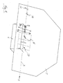
- Figure 1 shows a simplified overall view of the device with a frame 1, with a supported by the frame, backwardly inclined support wall 2, with a provided in the lower region of the support wall 2 horizontal Conveyor track 3, along which to be bent hollow profile rods in the conveying direction. 4 a bending tool 5 are supplied.
- a feed device is provided, which in the embodiment preferably from two endless, mutually parallel, synchronously driven Timing belts 6 and 7 are made which have pairs of gears 8 and 9 as well 8a and 9a are guided, of which the front gears 8, 8a driven are.
- Timing belt 6 and 7 variable in their mutual distance, in particular by moving the upper toothed belt 7 together with its gears 8 and 9.
- further tools may be arranged in particular a saw for severing the hollow profile bars, a labeling device for inscribing the hollow profile bars, and a connecting device for connecting successive sections of hollow profile bars.
- a connection device consists for example of a stationary Clamping jaw pair 10 and from a longitudinally displaceable on the conveyor track 3 Clamping jaw pair 11.
- the front hollow profile bar is near its rear end between fixed the stationary jaws 10 and the subsequent hollow profile bar set near its front end between the movable jaws 11, wherein one of the two ends carries a connector which passes through Advancing the second jaw pair 11 also in the opposite The end of the other hollow profile bar is pushed.
- the legs of the hollow profile bars to be bent are in the illustrated device, in which the conveying direction 4 runs from left to right, contrary bent clockwise, with the bent legs on the Supporting wall 2 can be supported and guided on it.
- the conveying direction 4 from left to right is arbitrary, it could also be from the right to the left; In this case, the hollow profile bars would be clockwise bent.
- the conveyor track 3 is not formed as a continuous continuous track, but consists of a sequence of partially different elements, which the hollow profile bars both parallel to the support wall 2 and in a thereto support and guide vertical plane while maintaining a straight, horizontal Force movement path of the hollow profile bars.
- the determine the trajectory of the hollow profile bars include the Timing belts 6 and 7, the jaw pairs 10 and 11 and the bending tool 5, which is shown in more detail in Figure 2.
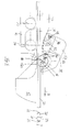
- Essential components of the bending tool 5 are a bending cheek 12, a with her cooperating counter-holder 13, a bending brace 14 and a Support 16, which is arranged on the same side of the hollow profile bar 20, as the bending machine 12, based on the conveying direction 4 behind the bending cheek. These components are in Figure 2 in a view with a viewing direction shown perpendicular to the support surface 2, of the two-piece bending support 14 but only the first rear abutment part 14a.
- Both the bending beam 12 and its counter-holder 13 are at a respect of the bending support 14 eccentrically oriented, perpendicular to the support wall 2 oriented Pivot axis 18 pivotable.
- the bending beam 12 is behind the plane of the support wall 2, preferably an electric servomotor provided, which allows predetermined swivel angle especially to execute exactly.
- the bending beam 12 by means of a pneumatic cylinder, in particular a rotary wing cylinder, to pivot.
- the anvil 13 has no own pivot drive, it is of the bending beam 12 taken when this in the direction of arrow 19 a Swivel movement performs.
- the counter-holder 13 against the on Bending cheek 12 lying portion of the hollow profile bar 20 is pressed or pulled, Preferably by means of a pneumatic cylinder, the in the drawings not shown and its resistance from the drive motor of the bending cheek 12 is overcome.
- a hollow profile bar to be bent 20 during the bending process between the bending beam 12 and her Contra-holder 13 is clamped.
- the inner wall 23 of the hollow profile bar 20 presses against the nose 34 can be provided between the bending beam 12 and the anvil 13 a stop be, the approach of the counter-holder 13 to the bending beam 12 on a limited by the height of the hollow section bar 20 dimension bounded; one such stop can be e.g. by a turned into the anvil 13 and against the bending beam 12 directed screw be formed.
- the hollow profile rod 20 is fed to the bending tool on the conveyor track 3, that its outer wall 21 points downwards and abuts the bending beam 12, that its mutually parallel flanks 22 extend parallel to the support wall 2 and that its inner wall 23 faces the counter-holder 13.
- Both shown hollow profile bars 20 are box sections, for which the Invention is particularly suitable. It is basically also suitable for Bar profiles, if they are to be bent, as long as they are unfilled.
- the indications "inside” and “outside” are chosen with regard to the corner to be bent, which has an outside and an inside, so that the "inner wall” the inside and the "outside wall” forms the outside of the corner.
- the support 16 is by means of a pressure medium cylinder, not shown by means of a pivotable at right angles to the support wall 2 extending shaft 25.
- the support 16 prevents the rear section of the hollow section bar from bending not deflected and supports his leadership in the feed.
- the support 16 from the in Figure 2 shown position if necessary, be pivoted slightly downwards; the bending cheek 12 is located in the starting position shown in Figure 2 or, if necessary, in a slightly downwards pivoted Position; the counter-holder 13 is located during the advancement of the hollow profile rod 20 preferably in the position shown in Figure 6, in which the bending abutment 14 has its greatest possible distance from the level 17, in which the hollow profile bar 20 facing surfaces of the support 16 and the Biegewange 12 are aligned in their initial position with each other.
- the hollow section bar 20 by its feed device 6 to 8 between the flexural deflector 14 and the anvil 13 on the one hand and the support 16 and the bending beam 12 on the other side advanced.
- the hollow section bar 20 is advanced until the point at which a corner is bent is to be achieved, the bending spreader 14.
- the correct position can determined by a displaceable along the conveyor track 3 stop 27 ( Figure 1) be, on which the front end of the hollow profile rod 20 abuts and shut down. After that, the support 16, if they are not in the Level 17 was in this swung. Instead of a stop 27 can the correct position but also in software from given production data and feed data.
- FIG Top view with a view parallel to the support surface 2 shown. you sees the pivot axis 18 and the bending beam 12.
- a support 32 is fixedly mounted, which interchangeable a fixed Jaws 33 carries, which is the rear edge of the hollow profile bar facing, which is not shown in Figure 3.
- the shaft 25 is supported, which carries the support 16 and rotates.
- the shaft 25 and the rod 24 are for this purpose in their Slidable longitudinally, so that the second jaw 35 in the direction of the arrow 37 the jaw 33 and thus the preceding hollow profile bar 20 can be approximated.
- the second jaw 35 also carries a jaw 38 ( Figure 3), which is rotatable about the pivot axis 18 in a Recess of the second jaw 35 is mounted.
- the rotatable jaws 38 together with one of the trailing edge 22 of the hollow profile bar 20th facing another jaw 36, which also about the pivot axis 18th is rotatably mounted on an extension 12a of the bending beam 12, a second Clamping device with which the flanks 22 of the hollow profile bar in the immediate Environment of the pivot axis 18 can be clamped.
- the Bakken 36 and 38 are eccentrically mounted; they extend along the to be bent Leg of the hollow section bar 20 over a greater length than along his unbendable thigh.
- the rear jaw 36 is from the anvil 13 taken.
- the front jaw 38 is formed by a positive Engagement of a provided on the anvil 13 driver 39 in a Recess of the front jaw 38 taken from the anvil 13; the procedure is similar to a dovetail connection and remains shortened, when the front jaw 38 increases its distance from the mounting wall 30.
- the second, front abutment part 14b is, as best shown in the figure 5 rotatably mounted rotatably in a recess 41 of the jaw 35, Why the front jaw 38 has a pin 42a on its back, which engages in a matching bush 43a of the jaw 35.
- Around the front jaws 38 captive in the recess 41 of the jaw 35 is to hold the recess 41 with a circular arc-shaped undercut 44 provided, in which the jaw 38 with a corresponding arcuate Projection 45 engages, which is approximately over a circumferential angle of Extends 180 °.
- the front jaw 38 In the bending process, the front jaw 38, based on the 5, rotated in the clockwise direction, whereby the engagement of the circular arc-shaped projection 45 in the circular arc-shaped undercut 44 is preserved. To replace the front jaw 38 against the Turned clockwise, whereby the circular arc-shaped projection 45 from the Undercut 44 can slip out. As long as the positive connection between the front jaw 38 and the jaws 35 is made, the front Bake 38 when adjusting the jaw 35 taken by this and moved into its clamping position on the hollow profile bar or from the clamping position moved out.
- the front flexural damper 14b is connected to the front Baking 38 screwed.
- the unit formed thereby has a recess 47, in which the driver 39 engages positively. In this way both become Abutment parts 14a and 14b inevitably with the anvil 13th pivoted.
- FIG. 5 shows in detail the contour of the nose 34 of the abutment parts 14a, 14b a substantially cylindrical first peripheral portion 26a and a in substantially planar second peripheral portion 26b.
- the nose 34 of the jaw 38 maintains a distance; this distance is at least twice the wall thickness of the hollow profile bar, so this can be dented by the peripheral portion 26a, without the flanks 22 damage.
- the hollow profile bar 20 is first clamped between the various clamping devices. Thereafter, by bending the bending beam 12 of the bending operation can be performed, wherein the maximum bending angle is reached when the anvil 13 abuts the jaw 33.
- the counter-holder 13 and the clamping jaw 33 are wedge-shaped, wherein the wedge tips are directed against the flexural abutment 14.
- An inclined surface 28 of the counter-holder 13 and an inclined surface 29 of the jaw 33, which are on the side facing away from the conveyor 3 side of the counter-holder 13 and the jaws 33 are arranged so that the counter-holder 13 with its inclined surface 28 over the entire surface of the inclined surface 29 of Clamping jaw 33 can strike, see Figure 6.
- the flexural deflector 14 has a first peripheral portion 26a with a substantially cylindrical lateral surface and a second, flattened peripheral portion 26b, both of which lie on the same side of the pivot axis 18.
- the distance of the first peripheral portion 26a of the bending support 14 from the plane 17, in which the hollow profile bar 20 facing surfaces of the bending beam 12 and the support 16 are aligned slightly smaller than the height of the hollow profile rod 20, so that the inner wall 23 before is dented the bending process, namely, when the counter-holder 13 and / or the bending beam 12 are pivoted to its position shown in Figure 2. At this point is then the center of the bend.
- the hollow profile rod 20 is then from the engagement of the bending support 14th completely free and can be advanced in the conveying direction 4 up to his next bending point, where he again in the manner described can be clamped and then bent.
- the release of the procedure the bending support of the hollow section bar 20 is done with the simplest means and guaranteed in particular, that the hollow profile rod 20 when advancing at its Interior wall is not touched and there are no sanding marks, especially would be distracting on painted surfaces, because the inner wall of the hollow profile bar later clearly visible in the insulating glass pane.
- the hollow profile rod 20 on both sides the bending point are clamped, if necessary even on all sides.
- This can on the outer wall 21 and on the flanks 22 when bending a well-defined and -wenn desired- also a larger train to be exercised than in the state of Technique, what to avoid wrinkling in the area of emerging Corner favors and improves the quality of the bend.
- the anvil 13 can be replaced together with the flexural abutment 14 and replaced by a filled with drying agent hollow profile rods special suitable arrangement of counter-holder, bending support and a support 16 opposite the clamping part, against which the support 16 can clamp the hollow section bar 20 and in which the bending abutment is formed by a hinge-like connection of the counter-holder with the clamping part.
- a hinge-like design of the bending support makes this despite small dimensions particularly resistant to the larger forces occurring during the bending of filled hollow profile bars.
- An example of such a bending tool is in the German patent application 101 38 345.2.
- a slot-like recess 46 which is open towards the end of the counter-holder 13.
- the counter-holder 13 is also a parallel to the pivot axis 18 bore 48, which lies between the recess 46 and the bending support bearing 14.
- a pin 49 and parallel thereto is in the support 57, a further axially parallel bore 50, which has a distance from the pin 49, which the distance of the bore 48th from the recess 46 corresponds.
- a locking pin 52 In the bore 50 is a locking pin 52, which by a resilient Pressure piece 54 is secured against moving out. After loosening the grub screw 54, the locking pin 52 pulled out and the Geumblehalter 13 be taken. This is a lightning fast tool change possible.
Landscapes
- Engineering & Computer Science (AREA)
- Mechanical Engineering (AREA)
- Bending Of Plates, Rods, And Pipes (AREA)
- Re-Forming, After-Treatment, Cutting And Transporting Of Glass Products (AREA)
Abstract
- mit einem Gestell (1),
- mit einem vom Gestell (1) getragenen Biegewerkzeug (5) welches
- eine Biegewange (12), welche um eine Schwenkachse (18) verschwenkbar ist, zum Biegen auf die Außenwand (21) des Hohlprofilstabes (20) einwirkt und eine Ausgangslage hat, welche sie vor dem Biegen einnimmt,
- einen um dieselbe Schwenkachse (18) verschwenkbaren Gegenhalter (13) zum Anlegen an die Innenwand (23)
- und ein der Innenwand (23) zugewandtes Biegewiderlager (14) aufweist, um welches herum der Hohlprofilstab (20) gebogen wird,
- mit einer ersten Klemmeinrichtung, welche auf der der Biegewange (12) in der
Ausgangslage abgewandten Seite der Schwenkachse (18) angeordnet ist und
- ein erstes Klemmteil (15) zum Einwirken auf die Innenwand (23) und
- ein zweites Klemmteil (16) zum Einwirken auf die Außenwand (21) des Hohlprofilstabes (20) aufweist.
Description
Für die Herstellung von Abstandhalterrahmen für Isolierglasscheiben sind zwei Typen von Hohlprofilstäben gebräuchlich. Am häufigsten werden sogenannte Kastenprofile verwendet, bei welchen die Innenwand rechtwinklig von zueinander parallelen Flanken des Hohlprofilstabes ausgeht und die Außenwand in einem mittleren Bereich parallel zur Innenwand läuft und beidseits über Schrägflächen mit den Flanken verbunden ist. Die Angaben "innen" und "außen" sind hierbei vom fertig gebogenen Abstandhalterrahmen abgeleitet: Die Innenwand weist in das Innere der Isolierglasscheibe; die Außenwand weist in die entgegengesetzte Richtung. Bei dem anderen Typ, welcher ebenfalls gebräuchlich ist, stehen die zueinander parallen Flanken über die Innenwand vor, wobei der Abstand zwischen Innenwand und Außenwand in der Regel kleiner ist, als bei Kastenprofilen. Dieser Profiltyp, bei dem die Flanken über die Innenwand vorstehen, wird auch als Stegprofil bezeichnet. Stegprofile haben gegenüber Kastenprofilen den Vorteil, dass ihre Innenwand beim Biegen weniger stark verformt werden muss, weil sie näher bei der "neutralen Phase" liegt. Stegprofile werden meistens gebogen, nachdem sie mit einem körnigen Trockenmittel gefüllt sind, welches die Abstandhalterrahmen enthalten müssen, bevor sie in die Isolierglasscheibe eingebaut werden. Die Erfindung eignet sich besonders für das Biegen von Hohlprofilstäben, die noch leer sind, insbesondere für solche mit Kastenprofilen. Beim Biegen von Kastenprofilen hat sich ein Biegewiderlager bewährt, in welchem die Widerlagerteile in einem ersten Umfangsabschnitt eine überwiegend zylindrische Mantelfläche mit einem Radius von 2 mm bis 3 mm, insbesondere 2,5 mm haben.
- Figur 1
- zeigt eine vereinfachte Gesamtansicht der Vorrichtung,
- Figur 2
- zeigt einen Teil des Biegewerkzeugs der Vorrichtung in einer Vorderansicht,
- Figur 3
- ist eine Draufsicht auf das Biegewerkzeug ohne Klemmteil,
- Figur 4
- ist eine Schnittansicht des Biegewerkzeuges gemäß der Schnittlinie A-A in Figur 3,
- Figur 5
- zeigt vergrößert ein Detail aus Figur 4, und
- Figur 6
- zeigt in einer Ansicht entsprechend der Figur 1 das Biegewerkzeug, in welchem der Gegenhalter in seine wirksame Endstellung verschwenkt ist, in welcher das Biegewiderlager unwirksam ist.
Das Biegewiderlager 14 hat einen ersten Umfangsabschnitt 26a mit einer im wesentlichen zylindrischen Mantelfläche und einen zweiten, abgeflachten Umfangsabschnitt 26b, welche beide auf derselben Seite der Schwenkachse 18 liegen. Vorzugsweise ist der Abstand des ersten Umfangsabschnittes 26a des Biegewiderlagers 14 von der Ebene 17, in welcher die dem Hohlprofilstab 20 zugewandten Oberflächen der Biegewange 12 und der Stütze 16 miteinander fluchten, etwas kleiner als die Höhe des Hohlprofilstabes 20, so dass dessen Innenwand 23 schon vor dem Biegevorgang eingedellt wird, nämlich dann, wenn der Gegenhalter 13 und/oder die Biegewange 12 in ihre in Figur 2 dargestellte Stellung geschwenkt werden. An genau dieser Stelle befindet sich dann das Zentrum der Biegestelle. Infolge der gewählten Anordnung und Gestalt des zweiten Umfangsabschnittes 26b des Biegewiderlagers 14 ist dessen Abstand von der Ebene 17 größer als der Abstand des ersten Umfangsabschnittes 26a, wenn sich der Gegenhalter 13 in der in Figur 6 dargestellten Anschlagstellung oder in deren Nähe befindet. Es sei noch darauf hingewiesen, dass die Umfangskontur für beide Widerlagerteile 14a und 14b gleich gewählt ist.
101 38 345.2 offenbart. Zum Zweck des Austausches hat der Gegenhalter 13 an seinem der Schwenkachse 18 abgewandten Ende eine langlochartige Ausnehmung 46, welche zum Ende des Gegenhalters 13 hin offen ist. Im Gegenhalter 13 befindet sich darüberhinaus eine zur Schwenkachse 18 parallele Bohrung 48, welche zwischen der Ausnehmung 46 und dem Biegewiderlager 14 liegt. In einer Bohrung eines um die Schwenkachse 18 schwenkbaren Trägers 57 für den Gegenhalter 13 steckt ein Stift 49 und parallel dazu befindet sich in dem Träger 57 noch eine weitere achsparallele Bohrung 50, welche von dem Stift 49 einen Abstand hat, welcher dem Abstand der Bohrung 48 von der Ausnehmung 46 entspricht.
Claims (25)
- Vorrichtung zum Biegen von Hohlprofilstäben (20), insbesondere für Abstandhalterrahmen für Isolierglasscheiben, wobei die Hohiprofilstäbe (20) zwei zu einander parallele Flanken (22) sowie eine Innenwand (23) und eine Außenwand (21) haben, welche die Flanken (22) miteinander verbinden,dadurch gekennzeichnet, dass das Biegewiderlager (14) mittels eines eigenen Antriebs um die Schwenkachse (18) der Biegewange (12) oder um eine ihr benachbarte und zu ihr parallele Achse verschwenkbar ist und dass die beiden Widerlagerteile (14a, 14b) in Bezug auf ihre Schwenkachse (18) eine in der Weise exzentrisch ausgebildete Gestalt haben, dass sie einen ersten Umfangsabschnitt (26a ) haben, welcher der Innenwand (23) des Hohlprofilstabes (20) während des Biegevorgangs anliegt und dass sie an den ersten Umfangsabschnitt ( 26a) anschließend einen zweiten Umfangsabschnitt (26b) haben, welcher durch Verschwenken des Biegewiderlagers (14) der Innenwand (23) des Hohlprofilstabes (20) zugewandt werden kann und in der dann gegebenen Lage von der Ebene (17), in welcher die dem Hohlprofilstab (20) zugewandte Seite der Stütze (16) und der Biegewange (12) miteinander fluchten, einen größeren Abstand haben, als der erste Umfangsabschnitt (26a) in seiner dieser Ebene (17) zugewandten Lage.mit einem Gestell (1),mit einem vom Gestell (1) getragenen Biegewerkzeug (5), welcheseine Biegewange (12) hat, welche um eine Schwenkachse (18) verschwenkbar ist, zum Biegen auf die Außenwand (21) des Hohlprofilstabes (20) einwirkt
und eine Ausgangslage hat, welche sie vor dem Biegen einnimmt,ein der Innenwand (23) zugewandtes Biegewiderlager (14) aufweist, um welches herum der Hohlprofilstab (20) gebogen wird, und welches zwei Widerlagerteile (14a, 14b) hat, deren gegenseitiger Abstand veränderbar ist,und eine Stütze (16) zum Stützen der Außenwand (21) des Hohlprofilstabes (20) aufweist, welche auf der der Ausgangslage der Biegewange (12) abgewandten Seite ihrer Schwenkachse (18) angeordnet ist - Vorrichtung nach Anspruch 1, dadurch gekennzeichnet, dass das Biegewiderlager (14) wahlweise auch gemeinsam mit der Biegewange (12) um dessen Schwenkachse (18) verschwenkbar ist.
- Vorrichtung nach Anspruch 1 oder 2, dadurch gekennzeichnet, dass das Biegewiderlager (14) oder eines seiner Teile 14a an der Spitze eines der Biegewange (12) gegenüberliegenden Gegenhalters (13) angeordnet ist, welcher zum Anlegen an die Innenwand (23) des Hohlprofilstabs (20) ausgebildet ist.
- Vorrichtung nach Anspruch 3, dadurch gekennzeichnet, dass die der Innenwand (23) des Hohlprofilstabes (20) zugewandte Oberfläche des Gegenhalters (13) eben ausgebildet ist.
- Vorrichtung nach Anspruch 3 oder 4, dadurch gekennzeichnet, dass der Gegenhalter (13) keilförmig ausgebildet ist, wobei die Keilspitze zum Biegewiderlager (14) weist.
- Vorrichtung nach einem der vorstehenden Ansprüche, dadurch gekennzeichnet, dass die Stütze (16) um eine zur Schwenkachse (18) parallele Achse (25) verschwenkbar ist.
- Vorrichtung nach Anspruch 6, dadurch gekennzeichnet, dass in der Nachbarschaft der Stütze (16) ein hinterer Klemmbacken (13) und ein vorderer Klemmbacken (35) vorgesehen sind, welche zum Klemmen der Flanken (22) des Hohlprofilstabs (20) bestimmt sind, und dass der hintere Klemmbacken (33) keilförmig ausgebildet ist, wobei die Keilspitze zum Biegewiderlager (14) weist.
- Vorrichtung nach Anspruch 7, dadurch gekennzeichnet, dass die Keilfläche des Gegenhalters (13) durch Verschwenken des Gegenhalters (13) zur flächigen Anlage an der ihr zugewandten Anlage des hinteren Klemmbackens (33) gebracht werden kann.
- Vorrichtung nach Anspruch 7 oder 8, dadurch gekennzeichnet, dass die Keilwinkel des Gegenhalters (13) und des hinteren Klemmbackens (33) zusammengenommen kleiner als 50°, insbesondere kleiner als 30°, sind.
- Vorrichtung nach einem der vorstehenden Ansprüche, dadurch gekennzeichnet, dass die Widerlagerteile (14a, 14b) in einem ersten Umfangsabschnitt (26a) eine überwiegend zylindrische Mantelfläche haben.
- Vorrichtung nach Anspruch 10, dadurch gekennzeichnet, dass für das Biegen von Hohlprofilstäben (20) mit kastenförmigem Querschnitt (Kastenprofile) der Radius der Mantelfläche des ersten Umfangsabschnitts (26a ) 2 mm bis 3 mm, insbesondere 2,5 mm, beträgt.
- Vorrichtung nach einem der vorstehenden Ansprüche, dadurch gekennzeichnet, dass beide Widerlagerteile (14a, 14b) in ihrem ersten Umfangsabschnitt (26a), welcher beim Biegen dem Hohlprofilstab 20 zugewandt ist, eine übereinstimmende Kontur haben.
- Vorrichtung nach einem der vorstehenden Ansprüche, dadurch gekennzeichnet, dass die Widerlagerteile (14a, 14b) auf ihrer Rückseite, welche dem ersten Umfangsabschnitt (26a) abgewandt ist, einen abgeflachten zweiten Umfangsabschnitt (26a) haben.
- Vorrichtung nach einem der vorstehenden Ansprüche, dadurch gekennzeichnet, dass der erste und der zweite Umfangsabschnitt (26a) beide auf derselben Seite der Schwenkachse (18) liegen.
- Vorrichtung nach einem der vorstehenden Ansprüche, dadurch gekennzeichnet, dass das Biegewiderlager (14) auswechselbar ist.
- Vorrichtung nach Anspruch 15, dadurch gekennzeichnet, dass das Biegewiderlager (14) an einem um die Schwenkachse (18) der Biegewange (12) verschwenkbaren Träger (57) lösbar befestigt ist.
- Vorrichtung nach Anspruch 16, dadurch gekennzeichnet, dass der Gegenhalter (13) an seinem der Schwenkachse (18) abgewandten Ende eine zu diesem Ende hin offene Ausnehmung (46) hat, dass vom schwenkbaren Träger (57) ein achsparalleler Stift (49) vorsteht, der zum Eingreifen in die Ausnehmung (46) bestimmt ist, und dass zum Festlegen des Biegewiderlagers (14) mit dem Gegenhalter (13) am schwenkbaren Träger (57) Mittel (52) vorgesehen sind, welche zusätzlich an einer von dem Stift (49) entfernten Stelle den Gegenhalter (13) an dem schwenkbaren Träger (57) lösbar festhält.
- Vorrichtung nach Anspruch 17, dadurch gekennzeichnet, dass zum Festlegen des Gegenhalters (13) mitsamt dem Biegewiderlagers (14) ein Stift (52) oder eine Schraube vorgesehen ist, welche durch den Gegenhalter (13) in den mit der Biegewange (12) oder relativ zu der Biegewange (12) verschwenkbaren Träger (57) eingeführt wird.
- Vorrichtung nach einem der vorstehenden Ansprüche, dadurch gekennzeichnet, dass im Bereich der Schwenkachse (18) eine auf die Flanken (22) des Hohlprofilstabes (20) einwirkende zweite Klemmeinrichtung (12a, 38) vorgesehen ist.
- Vorrichtung nach Anspruch 19, dadurch gekennzeichnet, dass die zweite Klemmeinrichtung (12a, 38) mit dem Biegewiderlager verschwenkbar ist.
- Vorrichtung nach Anspruch 20, dadurch gekennzeichnet, dass das eine Widerlagerteil (14a) mit einem hinteren Backen (36) der zweiten Klemmeinrichtung und das andere Widerlagerteil (14b) mit einem vorderen Backen (38) der zweiten Klemmeinrichtung gekoppelt ist, dessen Abstand vom hineren Bakken (36) der zweiten Klemmeinrichtung veränderbar ist.
- Vorrichtung nach Anspruch 21, dadurch gekennzeichnet, dass die Widerlagerteile (14a, 14b) lösbar mit den Backen (36, 38) gekoppelt sind.
- Vorrichtung nach Anspruch 21 oder 22, dadurch gekennzeichnet, dass am Gegenhalter (13) und/oder am daran angebrachten ersten Widerlagerteil (14a) ein Mitnehmer (39) angebracht ist, welcher am zweiten Widerlagerteil (14b) und/oder am zweiten, abstandsveränderlichen Teil (38) der zweiten Klemmeinrichtung angreift und es mitnimmt.
- Vorrichtung nach einem der vorstehenden Ansprüche, dadurch gekennzeichnet, dass auf der der Biegewange (12) in ihrer Ausgangslage abgewandten Seite der Schwenkachse (18) eine auf die Flanken (22) des Hohlprofilstabes (20) einwirkende dritte Klemmeinrichtung (33, 35) vorgesehen ist.
- Vorrichtung nach einem der vorstehenden Ansprüche, dadurch gekennzeichnet, dass mit der Biegewange (12) eine mit ihr verschwenkbare, auf die Flanken (22) des Hohlprofilstabes (20) einwirkende vierte Klemmeinrichtung (40, 41) verbunden ist.
Applications Claiming Priority (2)
| Application Number | Priority Date | Filing Date | Title |
|---|---|---|---|
| DE10236407 | 2002-08-02 | ||
| DE10236407A DE10236407B4 (de) | 2002-08-02 | 2002-08-02 | Vorrichtung zum Biegen von Hohlprofilstäben |
Publications (3)
| Publication Number | Publication Date |
|---|---|
| EP1393831A2 true EP1393831A2 (de) | 2004-03-03 |
| EP1393831A3 EP1393831A3 (de) | 2004-11-03 |
| EP1393831B1 EP1393831B1 (de) | 2007-09-26 |
Family
ID=30775091
Family Applications (1)
| Application Number | Title | Priority Date | Filing Date |
|---|---|---|---|
| EP03015669A Expired - Lifetime EP1393831B1 (de) | 2002-08-02 | 2003-07-18 | Vorrichtung zum Biegen von Hohlprofilstäben |
Country Status (3)
| Country | Link |
|---|---|
| EP (1) | EP1393831B1 (de) |
| AT (1) | ATE374082T1 (de) |
| DE (2) | DE10236407B4 (de) |
Family Cites Families (7)
| Publication number | Priority date | Publication date | Assignee | Title |
|---|---|---|---|---|
| DE3312764A1 (de) * | 1983-04-09 | 1984-10-18 | Fr. Xaver Bayer Isolierglasfabrik Kg, 7807 Elzach | Verfahren und vorrichtung zum biegen von abstandhalter-profilen fuer isolierglasscheiben |
| ES2051110T5 (es) * | 1990-05-21 | 2002-07-16 | Peter Lisec | Procedimiento y dispositivo para la fabricacion de segmentos curvados en regletas de perfil hueco. |
| DK169909B1 (da) * | 1990-10-26 | 1995-04-03 | Bayer Isolierglasfab Kg | Bukkemaskine |
| AT406236B (de) * | 1995-10-31 | 2000-03-27 | Lisec Peter | Vorrichtung zum biegen oder krümmen von hohlprofilleisten |
| DE19733536C2 (de) * | 1997-08-02 | 2001-10-11 | Bayer Isolierglasfab Kg | Biegevorrichtung mit einem Niederhalter für Hohlprofile |
| DE20112827U1 (de) * | 2001-08-03 | 2001-12-20 | Lenhardt Maschinenbau GmbH, 75242 Neuhausen | Vorrichtung zum Biegen von Hohlprofilstäben |
| DE20113079U1 (de) * | 2001-08-03 | 2001-11-29 | Lenhardt Maschinenbau GmbH, 75242 Neuhausen | Vorrichtung zum Biegen von Hohlprofilstäben |
-
2002
- 2002-08-02 DE DE10236407A patent/DE10236407B4/de not_active Expired - Fee Related
-
2003
- 2003-07-18 DE DE50308268T patent/DE50308268D1/de not_active Expired - Lifetime
- 2003-07-18 AT AT03015669T patent/ATE374082T1/de active
- 2003-07-18 EP EP03015669A patent/EP1393831B1/de not_active Expired - Lifetime
Also Published As
| Publication number | Publication date |
|---|---|
| ATE374082T1 (de) | 2007-10-15 |
| EP1393831A3 (de) | 2004-11-03 |
| EP1393831B1 (de) | 2007-09-26 |
| DE50308268D1 (de) | 2007-11-08 |
| DE10236407B4 (de) | 2007-09-27 |
| DE10236407A1 (de) | 2004-02-26 |
Similar Documents
| Publication | Publication Date | Title |
|---|---|---|
| DE2627972C2 (de) | Schwenkbiegemaschine | |
| EP0497778B2 (de) | Vorrichtung zum biegen eines bleches | |
| DE2347768B2 (de) | Verfahren zum Herstellen von insbesondere hochfesten Ketten und Vorrichtung zum Durchführen des Verfahrens | |
| DE69009791T2 (de) | Vorrichtung zum Formen einer länglichen Blechplatte. | |
| DE10206773C1 (de) | Vorrichtung zum Vorschieben von Werkstücken mit Greiferschienen | |
| DE2531290C3 (de) | Verfahren zum Biegen von Kettengliedern und Kettengliedbiegemaschine zur Durchführung des Verfahrens | |
| DE1063570B (de) | Ausbreitvorrichtung fuer die Zufuehr-vorrichtung einer Buegelmaschine | |
| DE20104582U1 (de) | Dreiwalzen-Biegewerkzeug | |
| EP1872963A2 (de) | Vorrichtung zum Abpressen von Buchblocks | |
| EP0585613B1 (de) | Blechwalzmaschine | |
| EP1281451B1 (de) | Vorrichtung zum Biegen von Hohlprofilstäben | |
| EP0579593A1 (de) | Vorrichtung zum Herstellen von Abstandhalterrahmen für Isolierglasscheiben aus Hohlprofilleisten | |
| EP1281457B1 (de) | Vorrichtung zum Biegen von Hohlprofilstäben | |
| CH653928A5 (de) | Verfahren zum biegen von profilblechen und vorrichtung zur durchfuehrung des verfahrens. | |
| DE3938477C2 (de) | ||
| EP3456211B1 (de) | Vorrichtung zur halterung mindestens eines fingers | |
| EP1393831B1 (de) | Vorrichtung zum Biegen von Hohlprofilstäben | |
| EP0771597A1 (de) | Vorrichtung zum Biegen oder Krümmen von Hohlprofilleisten | |
| DE102014116192B4 (de) | Rohrbiegepresse | |
| DE20112142U1 (de) | Maschine für die Bearbeitung von Profilen | |
| EP1045499A1 (de) | Zange | |
| DE20212241U1 (de) | Vorrichtung zum Biegen von Hohlprofilstäben | |
| DE2113771C2 (de) | Vorrichtung zum Herstellen von C-förmigen zu verschweißenden Kettengliedern aus Draht | |
| DE102004060805A1 (de) | Verfahren und Vorrichtung zum Biegen von Hohlprofilstäben, insbesondere für Abstandhalterrahmen von Isolierglasscheiben | |
| DE20112827U1 (de) | Vorrichtung zum Biegen von Hohlprofilstäben |
Legal Events
| Date | Code | Title | Description |
|---|---|---|---|
| PUAI | Public reference made under article 153(3) epc to a published international application that has entered the european phase |
Free format text: ORIGINAL CODE: 0009012 |
|
| AK | Designated contracting states |
Kind code of ref document: A2 Designated state(s): AT BE BG CH CY CZ DE DK EE ES FI FR GB GR HU IE IT LI LU MC NL PT RO SE SI SK TR |
|
| AX | Request for extension of the european patent |
Extension state: AL LT LV MK |
|
| PUAL | Search report despatched |
Free format text: ORIGINAL CODE: 0009013 |
|
| AK | Designated contracting states |
Kind code of ref document: A3 Designated state(s): AT BE BG CH CY CZ DE DK EE ES FI FR GB GR HU IE IT LI LU MC NL PT RO SE SI SK TR |
|
| AX | Request for extension of the european patent |
Extension state: AL LT LV MK |
|
| 17P | Request for examination filed |
Effective date: 20041120 |
|
| AKX | Designation fees paid |
Designated state(s): AT BE BG CH CY CZ DE DK EE ES FI FR GB GR HU IE IT LI LU MC NL PT RO SE SI SK TR |
|
| GRAP | Despatch of communication of intention to grant a patent |
Free format text: ORIGINAL CODE: EPIDOSNIGR1 |
|
| GRAS | Grant fee paid |
Free format text: ORIGINAL CODE: EPIDOSNIGR3 |
|
| GRAA | (expected) grant |
Free format text: ORIGINAL CODE: 0009210 |
|
| AK | Designated contracting states |
Kind code of ref document: B1 Designated state(s): AT BE BG CH CY CZ DE DK EE ES FI FR GB GR HU IE IT LI LU MC NL PT RO SE SI SK TR |
|
| REG | Reference to a national code |
Ref country code: GB Ref legal event code: FG4D Free format text: NOT ENGLISH |
|
| REG | Reference to a national code |
Ref country code: CH Ref legal event code: EP |
|
| REF | Corresponds to: |
Ref document number: 50308268 Country of ref document: DE Date of ref document: 20071108 Kind code of ref document: P |
|
| REG | Reference to a national code |
Ref country code: IE Ref legal event code: FG4D Free format text: LANGUAGE OF EP DOCUMENT: GERMAN |
|
| REG | Reference to a national code |
Ref country code: CH Ref legal event code: NV Representative=s name: WILLIAM BLANC & CIE CONSEILS EN PROPRIETE INDUSTRI |
|
| PG25 | Lapsed in a contracting state [announced via postgrant information from national office to epo] |
Ref country code: FI Free format text: LAPSE BECAUSE OF FAILURE TO SUBMIT A TRANSLATION OF THE DESCRIPTION OR TO PAY THE FEE WITHIN THE PRESCRIBED TIME-LIMIT Effective date: 20070926 |
|
| NLV1 | Nl: lapsed or annulled due to failure to fulfill the requirements of art. 29p and 29m of the patents act | ||
| GBT | Gb: translation of ep patent filed (gb section 77(6)(a)/1977) |
Effective date: 20080307 |
|
| PG25 | Lapsed in a contracting state [announced via postgrant information from national office to epo] |
Ref country code: NL Free format text: LAPSE BECAUSE OF FAILURE TO SUBMIT A TRANSLATION OF THE DESCRIPTION OR TO PAY THE FEE WITHIN THE PRESCRIBED TIME-LIMIT Effective date: 20070926 Ref country code: GR Free format text: LAPSE BECAUSE OF FAILURE TO SUBMIT A TRANSLATION OF THE DESCRIPTION OR TO PAY THE FEE WITHIN THE PRESCRIBED TIME-LIMIT Effective date: 20071227 Ref country code: ES Free format text: LAPSE BECAUSE OF FAILURE TO SUBMIT A TRANSLATION OF THE DESCRIPTION OR TO PAY THE FEE WITHIN THE PRESCRIBED TIME-LIMIT Effective date: 20080106 |
|
| REG | Reference to a national code |
Ref country code: IE Ref legal event code: FD4D |
|
| PG25 | Lapsed in a contracting state [announced via postgrant information from national office to epo] |
Ref country code: PT Free format text: LAPSE BECAUSE OF FAILURE TO SUBMIT A TRANSLATION OF THE DESCRIPTION OR TO PAY THE FEE WITHIN THE PRESCRIBED TIME-LIMIT Effective date: 20080226 Ref country code: SK Free format text: LAPSE BECAUSE OF FAILURE TO SUBMIT A TRANSLATION OF THE DESCRIPTION OR TO PAY THE FEE WITHIN THE PRESCRIBED TIME-LIMIT Effective date: 20070926 Ref country code: CZ Free format text: LAPSE BECAUSE OF FAILURE TO SUBMIT A TRANSLATION OF THE DESCRIPTION OR TO PAY THE FEE WITHIN THE PRESCRIBED TIME-LIMIT Effective date: 20070926 |
|
| ET | Fr: translation filed | ||
| PG25 | Lapsed in a contracting state [announced via postgrant information from national office to epo] |
Ref country code: RO Free format text: LAPSE BECAUSE OF FAILURE TO SUBMIT A TRANSLATION OF THE DESCRIPTION OR TO PAY THE FEE WITHIN THE PRESCRIBED TIME-LIMIT Effective date: 20070926 Ref country code: SE Free format text: LAPSE BECAUSE OF FAILURE TO SUBMIT A TRANSLATION OF THE DESCRIPTION OR TO PAY THE FEE WITHIN THE PRESCRIBED TIME-LIMIT Effective date: 20071226 |
|
| PG25 | Lapsed in a contracting state [announced via postgrant information from national office to epo] |
Ref country code: DK Free format text: LAPSE BECAUSE OF FAILURE TO SUBMIT A TRANSLATION OF THE DESCRIPTION OR TO PAY THE FEE WITHIN THE PRESCRIBED TIME-LIMIT Effective date: 20070926 |
|
| PLBE | No opposition filed within time limit |
Free format text: ORIGINAL CODE: 0009261 |
|
| STAA | Information on the status of an ep patent application or granted ep patent |
Free format text: STATUS: NO OPPOSITION FILED WITHIN TIME LIMIT |
|
| 26N | No opposition filed |
Effective date: 20080627 |
|
| PG25 | Lapsed in a contracting state [announced via postgrant information from national office to epo] |
Ref country code: IE Free format text: LAPSE BECAUSE OF FAILURE TO SUBMIT A TRANSLATION OF THE DESCRIPTION OR TO PAY THE FEE WITHIN THE PRESCRIBED TIME-LIMIT Effective date: 20070926 |
|
| PG25 | Lapsed in a contracting state [announced via postgrant information from national office to epo] |
Ref country code: MC Free format text: LAPSE BECAUSE OF NON-PAYMENT OF DUE FEES Effective date: 20080731 |
|
| PG25 | Lapsed in a contracting state [announced via postgrant information from national office to epo] |
Ref country code: EE Free format text: LAPSE BECAUSE OF FAILURE TO SUBMIT A TRANSLATION OF THE DESCRIPTION OR TO PAY THE FEE WITHIN THE PRESCRIBED TIME-LIMIT Effective date: 20070926 |
|
| PG25 | Lapsed in a contracting state [announced via postgrant information from national office to epo] |
Ref country code: SI Free format text: LAPSE BECAUSE OF FAILURE TO SUBMIT A TRANSLATION OF THE DESCRIPTION OR TO PAY THE FEE WITHIN THE PRESCRIBED TIME-LIMIT Effective date: 20070926 |
|
| PG25 | Lapsed in a contracting state [announced via postgrant information from national office to epo] |
Ref country code: CY Free format text: LAPSE BECAUSE OF FAILURE TO SUBMIT A TRANSLATION OF THE DESCRIPTION OR TO PAY THE FEE WITHIN THE PRESCRIBED TIME-LIMIT Effective date: 20070926 |
|
| PG25 | Lapsed in a contracting state [announced via postgrant information from national office to epo] |
Ref country code: BG Free format text: LAPSE BECAUSE OF FAILURE TO SUBMIT A TRANSLATION OF THE DESCRIPTION OR TO PAY THE FEE WITHIN THE PRESCRIBED TIME-LIMIT Effective date: 20071226 |
|
| REG | Reference to a national code |
Ref country code: CH Ref legal event code: PFA Owner name: LENHARDT MASCHINENBAU GMBH Free format text: LENHARDT MASCHINENBAU GMBH#KARL-LENHARDT-STASSE 1-9#D-75242 NEUHAUSEN-HAMBERG (DE) -TRANSFER TO- LENHARDT MASCHINENBAU GMBH#KARL-LENHARDT-STASSE 1-9#D-75242 NEUHAUSEN-HAMBERG (DE) |
|
| PG25 | Lapsed in a contracting state [announced via postgrant information from national office to epo] |
Ref country code: LU Free format text: LAPSE BECAUSE OF NON-PAYMENT OF DUE FEES Effective date: 20080718 Ref country code: BE Free format text: LAPSE BECAUSE OF NON-PAYMENT OF DUE FEES Effective date: 20080731 Ref country code: HU Free format text: LAPSE BECAUSE OF FAILURE TO SUBMIT A TRANSLATION OF THE DESCRIPTION OR TO PAY THE FEE WITHIN THE PRESCRIBED TIME-LIMIT Effective date: 20080327 |
|
| PG25 | Lapsed in a contracting state [announced via postgrant information from national office to epo] |
Ref country code: TR Free format text: LAPSE BECAUSE OF FAILURE TO SUBMIT A TRANSLATION OF THE DESCRIPTION OR TO PAY THE FEE WITHIN THE PRESCRIBED TIME-LIMIT Effective date: 20070926 |
|
| REG | Reference to a national code |
Ref country code: CH Ref legal event code: PCAR Free format text: NOVAGRAAF SWITZERLAND SA;CHEMIN DE L'ECHO 3;1213 ONEX (CH) |
|
| PG25 | Lapsed in a contracting state [announced via postgrant information from national office to epo] |
Ref country code: IT Free format text: LAPSE BECAUSE OF NON-PAYMENT OF DUE FEES Effective date: 20130718 |
|
| PGRI | Patent reinstated in contracting state [announced from national office to epo] |
Ref country code: IT Effective date: 20141001 |
|
| PGFP | Annual fee paid to national office [announced via postgrant information from national office to epo] |
Ref country code: IT Payment date: 20140728 Year of fee payment: 11 |
|
| PGRI | Patent reinstated in contracting state [announced from national office to epo] |
Ref country code: IT Effective date: 20141001 |
|
| REG | Reference to a national code |
Ref country code: FR Ref legal event code: PLFP Year of fee payment: 14 |
|
| REG | Reference to a national code |
Ref country code: FR Ref legal event code: PLFP Year of fee payment: 15 |
|
| REG | Reference to a national code |
Ref country code: FR Ref legal event code: PLFP Year of fee payment: 16 |
|
| PGFP | Annual fee paid to national office [announced via postgrant information from national office to epo] |
Ref country code: GB Payment date: 20180822 Year of fee payment: 17 Ref country code: CH Payment date: 20180725 Year of fee payment: 16 |
|
| PGFP | Annual fee paid to national office [announced via postgrant information from national office to epo] |
Ref country code: DE Payment date: 20190517 Year of fee payment: 17 |
|
| PGFP | Annual fee paid to national office [announced via postgrant information from national office to epo] |
Ref country code: AT Payment date: 20190719 Year of fee payment: 17 |
|
| REG | Reference to a national code |
Ref country code: CH Ref legal event code: PL |
|
| GBPC | Gb: european patent ceased through non-payment of renewal fee |
Effective date: 20190718 |
|
| PG25 | Lapsed in a contracting state [announced via postgrant information from national office to epo] |
Ref country code: GB Free format text: LAPSE BECAUSE OF NON-PAYMENT OF DUE FEES Effective date: 20190718 |
|
| PG25 | Lapsed in a contracting state [announced via postgrant information from national office to epo] |
Ref country code: LI Free format text: LAPSE BECAUSE OF NON-PAYMENT OF DUE FEES Effective date: 20190731 Ref country code: CH Free format text: LAPSE BECAUSE OF NON-PAYMENT OF DUE FEES Effective date: 20190731 |
|
| PG25 | Lapsed in a contracting state [announced via postgrant information from national office to epo] |
Ref country code: FR Free format text: LAPSE BECAUSE OF NON-PAYMENT OF DUE FEES Effective date: 20190731 |
|
| REG | Reference to a national code |
Ref country code: DE Ref legal event code: R119 Ref document number: 50308268 Country of ref document: DE |
|
| REG | Reference to a national code |
Ref country code: AT Ref legal event code: MM01 Ref document number: 374082 Country of ref document: AT Kind code of ref document: T Effective date: 20200718 |
|
| PG25 | Lapsed in a contracting state [announced via postgrant information from national office to epo] |
Ref country code: DE Free format text: LAPSE BECAUSE OF NON-PAYMENT OF DUE FEES Effective date: 20210202 Ref country code: AT Free format text: LAPSE BECAUSE OF NON-PAYMENT OF DUE FEES Effective date: 20200718 |