EP1393886A1 - Procédé pour la fabrication d'une préforme pour une fibre optique en plastique - Google Patents
Procédé pour la fabrication d'une préforme pour une fibre optique en plastique Download PDFInfo
- Publication number
- EP1393886A1 EP1393886A1 EP03255437A EP03255437A EP1393886A1 EP 1393886 A1 EP1393886 A1 EP 1393886A1 EP 03255437 A EP03255437 A EP 03255437A EP 03255437 A EP03255437 A EP 03255437A EP 1393886 A1 EP1393886 A1 EP 1393886A1
- Authority
- EP
- European Patent Office
- Prior art keywords
- optical fiber
- plastic optical
- fabricating
- preform
- reactor
- Prior art date
- Legal status (The legal status is an assumption and is not a legal conclusion. Google has not performed a legal analysis and makes no representation as to the accuracy of the status listed.)
- Withdrawn
Links
Images

Classifications
-
- G—PHYSICS
- G02—OPTICS
- G02B—OPTICAL ELEMENTS, SYSTEMS OR APPARATUS
- G02B6/00—Light guides; Structural details of arrangements comprising light guides and other optical elements, e.g. couplings
-
- B—PERFORMING OPERATIONS; TRANSPORTING
- B29—WORKING OF PLASTICS; WORKING OF SUBSTANCES IN A PLASTIC STATE IN GENERAL
- B29D—PRODUCING PARTICULAR ARTICLES FROM PLASTICS OR FROM SUBSTANCES IN A PLASTIC STATE
- B29D11/00—Producing optical elements, e.g. lenses or prisms
- B29D11/00663—Production of light guides
- B29D11/00721—Production of light guides involving preforms for the manufacture of light guides
Definitions
- the present invention relates to a method for fabricating a preform for a plastic optical fiber, and more particularly to a method which can use monomers irrespective of their density to fabricate a preform for a plastic optical fiber, in which refractive index varies along the radial direction of the preform.
- Optical fibers used in the field of telecommunications are generally classified into single-mode fibers and multi-mode fibers in terms of the transmission mode of optical signal.
- Optical fibers currently used for long distance and high speed communications are mostly the step-index single-mode optical fibers based on quartz glass. These optical fibers have a diameter as small as 5 microns to 10 microns, and as a result, these glass optical fibers face serious challenges in terms of achieving proper alignment and connection. Accordingly, these glass optical fibers are associated with expensive costs relating to achieving proper alignment and connection.
- multi-mode glass optical fibers having a diameter that is larger than the diameter of single-mode optical fibers may be used for short distance communications such as in local area networks (LANs).
- LANs local area networks
- these multi-mode glass optical fibers in addition to being fragile, also suffer from expensive costs relating to achieving proper alignment and connection and therefore are not widely used. Accordingly, these multi-mode glass optical fibers have been mainly used for short distance communication applications up to 200 meters such as in LANs using a metal cable, for example, a twisted pair or coaxial cable.
- the data transmission capacity or bandwidth of the metal cable is as low as about 150 Mbps and can not reach transmission speed of 625 Mbps, which is a standard for the year 2000 in accordance with asynchronous transfer mode (ATM), it cannot satisfy the future standard of transmission capacity.
- ATM asynchronous transfer mode
- plastic optical fibers which can be used in short distance communication applications, such as LANs. Since the diameter of plastic optical fibers can be as large as 0.5 to 1.0 mm which is 100 or more times than that of glass optical fibers, due to its flexibility, its alignment and connection are much easier issues than with plastic optical fibers. Moreover, since polymer-based connectors may be produced by compression molding, these connectors can be used both for alignment and for connection and thereby reduce costs.
- the plastic optical fiber may have a step-index (SI) structure, in which a refractive index changes stepwise in a radial direction, or a graded-index (GI) structure, in which a refractive index changes gradually in a radial direction.
- SI step-index
- GI graded-index
- plastic optical fibers having a SI structure have high modal dispersion, the transmission capacity (or bandwidth) of a signal cannot be larger than that of cable.
- plastic optical fibers having a GI structure have a low modal dispersion, it can have a large transmission capacity. Therefore, it is known that GI plastic optical fiber is adequate for use as a communication medium for short distance, high-speed communications because of reduced costs derived from its larger diameter and large capacity of data transmission derived from low modal dispersion.
- the first method is a batch process wherein a preliminary cylindrical molding product, namely, a preform in which a refractive index changes in a radial direction, is fabricated, and then the resultant perform is heated and drawn to fabricate GI plastic optical fiber.
- the second method is a continuous process wherein a plastic fiber is produced by extrusion process, and then the low molecular material is extracted from the fiber, or contrarily introduced to the fiber to obtain GI plastic optical fiber.
- Van Duijnhoven and Bastiaansen reported another method for fabricating GI preform using high speed of rotation as high as about 20,000 rpm in WO 97/29903(U.S. Pat. No.6,166,107). Unlike the prior arts as mentioned above, this method uses the principle of centrifugal separation. When a mixture of monomers having different densities and refractive indices or a monomer dissolving a polymer is polymerized under very strong centrifugal field, concentration gradient is generated on account of a density gradient, and thereby, a refractive index gradient is generated.
- the above method is limited in the selection of monomers because one monomer of high density must have a refractive index lower than the other monomer of low density.
- a polymer having a low refractive index is dissolved in a monomer, there is a danger of contamination during polymerizing and grinding the polymer and dissolution of the polymer in the monomer is not easily achieved, which makes the dissolution process troublesome.
- a method for fabricating a preform for a plastic optical fiber comprising the steps of:
- the invention provides a method for fabricating a preform for a plastic optical fiber which is capable of using monomers irrespective of their density.
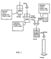
- Fig. 1 is a diagram schematically showing a series of processes for fabricating a preform for a plastic optical fiber in accordance with the present invention.
- a monomer solution having a relatively low refractive index is polymerized to form a prepolymer.
- the purpose of this process is to increase the density of the monomer.
- the other monomer solution having a relatively high refractive index is mixed with the prepolymer.
- the resulting mixture is fed into a cylindrical reactor, and polymerized with the reactor rotated to fabricate a preform for a plastic optical fiber.
- the preform for a plastic optical fiber thus fabricated has a refractive index profile varying along the radial direction.
- the term 'prepolymer' used herein means a state before a monomer is completely polymerized and solidified.
- the prepolymer has higher viscosity and density than the monomer prior to polymerizing.
- the present invention is characterized in that the prepolymer has higher density than the other monomer solution having a relatively high refractive index.
- the degree of polymerization of the prepolymer is determined by polymerization time and viscosity.
- the prepolymer used in the present invention has preferably a viscosity of about 50 ⁇ 500,000 cps (25°C), and more preferably 500 ⁇ 10,000 cps (25°C).
- the method of the present invention it is needless to select a pair of monomers, one of which has a lower refractive index and a higher density than the other because the monomer solution having a relatively low refractive index is prepolymerized to increase density, and then mixed with the monomer solution having a relatively high refractive index. Accordingly, the problem of contamination in the time of polymer grinding and dissolving as mentioned in U.S. Pat. No. 6,166,107, can be avoided and the fabricating process is simplified.
- a cavity is formed due to a volume shrinkage during the polymerization.
- a monomer solution having a relatively high refractive index a prepolymer of a monomer solution having a relatively low refractive index or a mixture of a monomer solution and a prepolymer, having a relatively high refractive index is added to the cavity and then polymerization is carried out.
- the above process can be repeated one or more times to obtain a perform without a cavity.
- a prepolymer having a low diffusion coefficient is used instead of a monomer solution, the occurrence of an indiscrete refractive index profile and optical loss due to the indiscrete refractive index profile can be minimized.
- Figs. 2A to 2C Various reactors usable in the present invention are depicted in Figs. 2A to 2C.
- a cylindrical reactor with a circular section is generally used.
- reactors with a triangular or a quadrangular section can be used depending on types of preforms intended to be fabricated.
- a rod-shaped reactor or other three dimensional reactors can be used.
- a cavity-preventing reactor described in U.S. Appln. Serial No. 10/197,215 which are incorporated herein by reference in its entirety, is available in the present invention. When the cavity-preventing reactor is used, additional adding of a reactant to the cavity is not needed because the reactant naturally flows from the introduction part to the cavity.
- the interior of the reactor using an inert gas such as argon to prevent the formation of a cavity, and to proceed polymerization in the reactor stably.
- an inert gas such as argon
- the interior of the reactor is pressurized, the boiling point of the monomer is raised and thus polymerization can be proceeded even at high temperature. Accordingly, the polymerization can be completed in a shortened time without formation of bubbles due to unreactants.
- the reactor is made of a fragile material, e.g., glass, quartz, ceramic or plastic, it is difficult to raise the internal pressure of the reactor to 4 bars or more. In this case, the exterior of the reactor is pressurized under the same pressure as applied to the interior of the reactor to avoid the breakage of the reactor.
- the rotational speed of the reactor can be varied.
- the variations can be not only a repeated rotation and stopping, but also a velocity function having varying amplitudes and cycles such as a trigonometric function.
- the term 'monomer solution' used herein refers to a solution which includes at least one monomer, a polymerization initiator and a chain transfer agent.
- a polymerization initiator a photopolymerization initiator or thermal polymerization initiator can be used.
- a combination of the photopolymerization initiator and the thermal polymerization initiator can be used to simultaneously proceed photopolymerization and thermal polymerization processes, thereby improving optical properties of a final optical fiber, such as refractive index distribution and optical loss.
- the monomer used in the present invention include, but are not limited to, methylmethacrylate, benzylmethacrylate, phenylmethacrylate, 1-methylcyclohexylmethacrylate, cyclohexylmethacrylate, chlorobenzylmethacrylate, 1-phenylethylmethacrylate, 1,2-diphenylethylmethacrylate, diphenylmethylmethacrylate, furfuryl methacrylate, 1-phenylcyclohexylmethacrylate, pentachlorophenylmethacrylate, pentabromophenylmethacrylate, styrene, TFEMA (2,2,2-trifluoroethylmethacrylate), TFPMA (2,2,3,3-tetrafluoropropylmethacrylate), PFPMA (2,2,3,3,3-pentafluoropropylmethacrylate), HFIPMA (1,1,1,3,3,3-hexafluofluo
- thermal polymerization initiator used in the present invention examples include, but are not limited to, 2,2'-azobis(isobutyronitrile), 1,1'-azobis(cyclohexanecarbonitrile), 2,2'-azobis(2,4-dimethylvaleronitrile), 2,2'-azobis(methylbutyronitrile), di-tert-butyl peroxide, lauroyl peroxide, benzoyl peroxide, tert-butyl peroxide, azo-tert-butane, azo-bis-isopropyl, azo-normal-butane, di-tert-butyl peroxide, etc.
- photopolymerization initiator used in the present invention examples include, but are not limited to 4-(para-tolylthio)benzophenone, 4,4'-bis(dimethylamino)benzophenone, 2-methyl-4'-(methylthio)-2-morpholino-propiophenone, 1-hydroxy-cyclohexyl-phenyl-ketone, 2-hydroxy-2-methyl-1-phenyl-propan-1-one, benzophenone, 1-[4-(2-hydroxyethoxy)-phenyl]-2-hydroxy-2-methyl-1-propan-1-one, 2-benzyl-2-methylamino-1-(4-morpholinophenyl)-butanone-1, 2,2-dimethoxy-1,2-diphenylmethan-1-one, bis(2,4,6-trimethylbenzoyl)-phenylphospinoxide, 2-methyl-1[4-(methylthio)phenyl]-2-morpholinopropan-1-one, bis(.eta.5-2,4-cyclopen
- chain transfer agent used in the present invention examples include, but are not limited to, normal-butyl-mercaptan, lauryl mercaptan, octyl mercaptan, dodecyl mercaptan, 1-butanethiol, etc.
- the preform In order to allow smooth heat transfer for the polymerization process in the fabrication of the preform for a plastic optical fiber, the preform preferably has a radius of 1 ⁇ 10cm.
- the length of the preform is preferably set to about 100cm or shorter suitable for a common thermal drawing.
- the preform for a plastic optical fiber fabricated in accordance with the method of the present invention is thermally drawn into a refractive index distributed type plastic optical fiber having a desired diameter. Furthermore, the method of the present invention is applicable to producing refractive index distributed type lenses and imaging guides for delivering images.
- a cylindrical reactor having a diameter of 50mm and a height of 400mm was used.
- a pair of monomers having different refractive indices benzyl methacrylate (hereinafter, referred to as 'BMA') and methyl methacrylate (hereinafter, referred to as 'MMA') were used.
- the density and the refractive index of BMA are 1.040 and 1.512, respectively, while those of MMA are 0.936 and 1.414, respectively. Comparing the two monomers in terms of their densities and the refractive indices, MMA has a relatively low density and refractive index.
- BMA having a relatively high refractive index and low density is distributed at the peripheral surface of a preform to be fabricated. Accordingly, a GI (Graded-Index) plastic optical fiber cannot be formed.
- a jacket reactor equipped with a circulator was used in a thermal polymerization initiator, while a transparent reactor equipped with a UV lamp was used in a photopolymerization initiator.
- thermal polymerization initiator and the photo polymerization initiator 2,2'-azobisisobutyronitrile (hereinafter, referred to as 'AIBN') and 4,4-bis(dimethylamino) benzophenone (hereinafter, referred to as 'DMABP') were used, respectively.
- 'AIBN' 2,2'-azobisisobutyronitrile
- 'DMABP' 4,4-bis(dimethylamino) benzophenone
- 1-butanethiol hereinafter, referred to as '1-BuSH' was used as a chain transfer agent.
- the optical loss of a plastic optical fiber was determined by drawing a 0.75mm thick optical fiber, cutting the drawn optical fiber at an interval of 1m, and measuring light intensity outputted from the ends of the cut optical fibers using a 650nm laser diode.
- AIBN and 1-BuSH were added to 510g of MMA in the concentration of 0.066% and 0.2% by weight, respectively.
- the mixture was charged into a cylindrical reactor, and polymerized at a temperature of 75 °C for 24 hours with the reactor rotated at a speed of 3,000rpm to form a clad layer.
- AIBN and 1-BuSH were added to 225g of MMA in the concentration of 0.066% and 0.2% by weight, respectively.
- the monomer solution thus prepared was charged into a jacket reactor, and polymerized at a temperature of 75 °C for 40 minutes to prepare a prepolymer.
- a monomer solution consisting of 80g of BMA containing 0.066% by weight of AIBN and 0.2% by weight of 1-BuSH was added and stirred for 2 minutes.
- the resulting mixture was filled into the cylindrical reactor in which the clad had been previously formed and polymerized at a temperature of 75°C for 12 hours with the reactor rotated at a speeded of 3,000rpm. Then, the rotational speed of the reactor was lowered to 100rpm and polymerization was continued for 12 hours to fabricate a preform for a plastic optical fiber. A 0.75mm thick plastic optical fiber was drawn from the preform. The optical loss of the plastic optical fiber was measured to be 210dB/km.
- AIBN and 1-BuSH were added to 510g of MMA in the concentration of 0.066% and 0.2% by weight, respectively.
- the mixture was charged into a cylindrical reactor, and polymerized at a temperature of 75 °C for 24 hours with the reactor rotated at a speed of 3,000 rpm to form a clad layer.
- DMABP and 1-BuSH were added to 225g of MMA in the concentration of 0.066% and 0.2% by weight, respectively.
- the monomer solution thus prepared was polymerized for 3 hours using UV lamp to prepare a prepolymer.
- a monomer solution consisting of 80g of BMA containing 0.066% by weight of DMABP and 0.2% by weight of 1-BuSH was added and stirred for 2 minutes.
- the resulting mixture was filled into the cylindrical reactor in which the clad had been previously formed, and polymerized at a temperature of 75 °C for 6 hours with the reactor rotated at a speed of 3,000rpm and irradiated with UV. Then, the polymerization was continued at a temperature of 85°C for 12 hours with the reactor rotated at a speed of 100 rpm to fabricate a preform for a plastic optical fiber. A 0.75mm thick plastic optical fiber was drawn from the preform. The optical loss of the plastic optical fiber was measured to be 190dB/km.
- AIBN and 1-BuSH were added to 510g of MMA in the concentration of 0.066% and 0.2% by weight, respectively.
- the mixture was polymerized at a temperature of 75°C for 3 hours to prepare a prepolymer.
- DMABP and 1-BuSH were added to a mixture of 225g of MMA and 80g of BMA in the concentration of 0.066% and 0.2% by weight, respectively.
- the prepared prepolymer was mixed thereto.
- the resulting mixture was filled into the cylindrical reactor at a temperature of 75 °C for 12 hours with the reactor rotated at a speeded of 3,000rpm and irradiated with UV.
- the polymerization was continued at a temperature of 85°C for 12 hours with the reactor rotated at a speed of 100 rpm to fabricate a preform for a plastic optical fiber.
- a 0.75mm thick plastic optical fiber was drawn from the preform.
- the optical loss of the plastic optical fiber was measured to be 195dB/km.
- AIBN and 1-BuSH were added to 510g of MMA in the concentration of 0.066% and 0.2% by weight, respectively.
- the mixture was charged into a cylindrical reactor, and polymerized at a temperature of 75 °C for 24 hours with the reactor rotated at a speed of 3,000rpm to form a clad layer.
- DMABP and 1-BuSH were added to 400g of MMA in the concentration of 0.066% and 0.2% by weight, respectively.
- the monomer solution thus prepared was polymerized at a temperature of 75°C for 20 minutes with UV irradiation to prepare a prepolymer.
- the fabricated preforms were an amorphous random copolymer.
Landscapes
- Engineering & Computer Science (AREA)
- Physics & Mathematics (AREA)
- Health & Medical Sciences (AREA)
- Manufacturing & Machinery (AREA)
- Ophthalmology & Optometry (AREA)
- Mechanical Engineering (AREA)
- General Physics & Mathematics (AREA)
- Optics & Photonics (AREA)
- Addition Polymer Or Copolymer, Post-Treatments, Or Chemical Modifications (AREA)
- Optical Fibers, Optical Fiber Cores, And Optical Fiber Bundles (AREA)
Applications Claiming Priority (2)
| Application Number | Priority Date | Filing Date | Title |
|---|---|---|---|
| KR2002051871 | 2002-08-30 | ||
| KR1020020051871A KR100707642B1 (ko) | 2002-08-30 | 2002-08-30 | 플라스틱 광섬유용 모재의 제조방법 |
Publications (1)
| Publication Number | Publication Date |
|---|---|
| EP1393886A1 true EP1393886A1 (fr) | 2004-03-03 |
Family
ID=31492919
Family Applications (1)
| Application Number | Title | Priority Date | Filing Date |
|---|---|---|---|
| EP03255437A Withdrawn EP1393886A1 (fr) | 2002-08-30 | 2003-08-29 | Procédé pour la fabrication d'une préforme pour une fibre optique en plastique |
Country Status (4)
| Country | Link |
|---|---|
| EP (1) | EP1393886A1 (fr) |
| JP (1) | JP4011000B2 (fr) |
| KR (1) | KR100707642B1 (fr) |
| CN (1) | CN1246347C (fr) |
Families Citing this family (3)
| Publication number | Priority date | Publication date | Assignee | Title |
|---|---|---|---|---|
| KR100707642B1 (ko) * | 2002-08-30 | 2007-04-13 | 삼성전자주식회사 | 플라스틱 광섬유용 모재의 제조방법 |
| CN106019466B (zh) * | 2016-06-03 | 2018-09-18 | 江西大圣塑料光纤有限公司 | 一种大直径柔性固态芯通体发光型塑料光纤的制备方法 |
| CN110187435B (zh) * | 2019-05-30 | 2020-12-01 | 山东光韵智能科技有限公司 | 一种远距离照明用多节点光纤及其制造方法 |
Citations (3)
| Publication number | Priority date | Publication date | Assignee | Title |
|---|---|---|---|---|
| US3955015A (en) * | 1972-10-23 | 1976-05-04 | Nippon Selfoc Co., Ltd. | Method of manufacturing a transparent light conducting element of synthetic resin having refractive index gradient |
| WO1996036478A1 (fr) * | 1995-05-15 | 1996-11-21 | Akzo Nobel N.V. | Procede de fabrication de fibres optiques polymeres a gradient d'indice |
| US6166107A (en) * | 1996-02-13 | 2000-12-26 | Technische University Eindhoven | Method for producing an optical rod-shaped graded-index polymer preform, preform obtained in accordance with this method and optical lens and optical fibre obtained by using same |
Family Cites Families (4)
| Publication number | Priority date | Publication date | Assignee | Title |
|---|---|---|---|---|
| JPH0312783A (ja) * | 1989-06-09 | 1991-01-21 | Matsushita Electric Ind Co Ltd | パターン検査方法 |
| JPH0420298A (ja) * | 1990-05-11 | 1992-01-23 | Hitachi Ltd | 骨髄像前処理装置および前処理方法 |
| KR100430389B1 (ko) * | 2001-07-18 | 2004-05-03 | 삼성전자주식회사 | 중공 방지형 반응기 및 이를 이용한 플라스틱 광섬유용모재의 제조방법 |
| KR100707642B1 (ko) * | 2002-08-30 | 2007-04-13 | 삼성전자주식회사 | 플라스틱 광섬유용 모재의 제조방법 |
-
2002
- 2002-08-30 KR KR1020020051871A patent/KR100707642B1/ko not_active Expired - Fee Related
-
2003
- 2003-08-29 EP EP03255437A patent/EP1393886A1/fr not_active Withdrawn
- 2003-09-01 CN CNB031649270A patent/CN1246347C/zh not_active Expired - Fee Related
- 2003-09-01 JP JP2003308768A patent/JP4011000B2/ja not_active Expired - Fee Related
Patent Citations (3)
| Publication number | Priority date | Publication date | Assignee | Title |
|---|---|---|---|---|
| US3955015A (en) * | 1972-10-23 | 1976-05-04 | Nippon Selfoc Co., Ltd. | Method of manufacturing a transparent light conducting element of synthetic resin having refractive index gradient |
| WO1996036478A1 (fr) * | 1995-05-15 | 1996-11-21 | Akzo Nobel N.V. | Procede de fabrication de fibres optiques polymeres a gradient d'indice |
| US6166107A (en) * | 1996-02-13 | 2000-12-26 | Technische University Eindhoven | Method for producing an optical rod-shaped graded-index polymer preform, preform obtained in accordance with this method and optical lens and optical fibre obtained by using same |
Also Published As
| Publication number | Publication date |
|---|---|
| JP4011000B2 (ja) | 2007-11-21 |
| KR100707642B1 (ko) | 2007-04-13 |
| JP2004094255A (ja) | 2004-03-25 |
| CN1246347C (zh) | 2006-03-22 |
| KR20040020298A (ko) | 2004-03-09 |
| CN1498907A (zh) | 2004-05-26 |
Similar Documents
| Publication | Publication Date | Title |
|---|---|---|
| JP4281889B2 (ja) | プラスチック光ファイバー用母材製造方法およびその方法を用いてなるプラスチック光ファイバー用母材 | |
| EP0472384A2 (fr) | Fibre optique en polymère et procédé pour sa fabrication | |
| EP0497984B1 (fr) | Procede de fabrication d'un milieu de transmission optique a partir d'une resine synthetique | |
| KR101041756B1 (ko) | 플라스틱 광학 파이버 및 그 제조 방법 | |
| US20040113297A1 (en) | Method for fabricating a preform for plastic optical fiber | |
| KR100707642B1 (ko) | 플라스틱 광섬유용 모재의 제조방법 | |
| EP1277555B1 (fr) | Réacteur anti-cavitation et procédé de fabrication d'une préforme de fibre optique dans un tel réacteur | |
| KR100430389B1 (ko) | 중공 방지형 반응기 및 이를 이용한 플라스틱 광섬유용모재의 제조방법 | |
| EP1393885A1 (fr) | Procédé pour la fabrication d'une préforme pour une fibre optique en plastique | |
| US20040113298A1 (en) | Method for fabricating a preform for plastic optical fiber | |
| JP2004054205A (ja) | プラスチック光学部材及び光学製品の製造方法並びにプラスチック光学製品及びプラスチック光ファイバ | |
| KR100368692B1 (ko) | 반경 방향으로 변화하는 물성을 지니는 봉형 고분자 모재,그의 제조방법 및 이에 사용되는 장치 | |
| KR100586362B1 (ko) | 순차적 자외광 중합을 이용한 플라스틱 광섬유용 모재의제조장치 및 방법 | |
| EP1583654A1 (fr) | Preforme utilisee dans la production de composants optiques en plastique, procede de fabrication de cette preforme et fibre optique plastique | |
| JPH0875931A (ja) | プラスチック光ファイバ母材及びその製造方法 | |
| KR20040064832A (ko) | 플라스틱 광섬유용 모재의 제조 방법 및 장치 | |
| JP2003344675A (ja) | 光伝送体の製造方法 | |
| JP2003195065A (ja) | プラスチック光学部材の製造方法 | |
| JP2003329859A (ja) | プラスチック光学部材の製造方法 | |
| JP2003329858A (ja) | プラスチック光学部材の製造方法 | |
| JP2003344674A (ja) | プラスチック光伝送体およびその製造方法 |
Legal Events
| Date | Code | Title | Description |
|---|---|---|---|
| PUAI | Public reference made under article 153(3) epc to a published international application that has entered the european phase |
Free format text: ORIGINAL CODE: 0009012 |
|
| AK | Designated contracting states |
Kind code of ref document: A1 Designated state(s): AT BE BG CH CY CZ DE DK EE ES FI FR GB GR HU IE IT LI LU MC NL PT RO SE SI SK TR |
|
| AX | Request for extension of the european patent |
Extension state: AL LT LV MK |
|
| 17P | Request for examination filed |
Effective date: 20040721 |
|
| AKX | Designation fees paid |
Designated state(s): BE DE FR GB |
|
| 17Q | First examination report despatched |
Effective date: 20081002 |
|
| STAA | Information on the status of an ep patent application or granted ep patent |
Free format text: STATUS: THE APPLICATION IS DEEMED TO BE WITHDRAWN |
|
| 18D | Application deemed to be withdrawn |
Effective date: 20090213 |