EP1394909A2 - Fibre optique amplificatrice et méthode de fabrication - Google Patents
Fibre optique amplificatrice et méthode de fabrication Download PDFInfo
- Publication number
- EP1394909A2 EP1394909A2 EP03018798A EP03018798A EP1394909A2 EP 1394909 A2 EP1394909 A2 EP 1394909A2 EP 03018798 A EP03018798 A EP 03018798A EP 03018798 A EP03018798 A EP 03018798A EP 1394909 A2 EP1394909 A2 EP 1394909A2
- Authority
- EP
- European Patent Office
- Prior art keywords
- optical fiber
- mole
- amplifying optical
- outer core
- cladding
- Prior art date
- Legal status (The legal status is an assumption and is not a legal conclusion. Google has not performed a legal analysis and makes no representation as to the accuracy of the status listed.)
- Withdrawn
Links
Images




Classifications
-
- G—PHYSICS
- G02—OPTICS
- G02B—OPTICAL ELEMENTS, SYSTEMS OR APPARATUS
- G02B6/00—Light guides; Structural details of arrangements comprising light guides and other optical elements, e.g. couplings
- G02B6/02—Optical fibres with cladding with or without a coating
-
- H—ELECTRICITY
- H01—ELECTRIC ELEMENTS
- H01S—DEVICES USING THE PROCESS OF LIGHT AMPLIFICATION BY STIMULATED EMISSION OF RADIATION [LASER] TO AMPLIFY OR GENERATE LIGHT; DEVICES USING STIMULATED EMISSION OF ELECTROMAGNETIC RADIATION IN WAVE RANGES OTHER THAN OPTICAL
- H01S3/00—Lasers, i.e. devices using stimulated emission of electromagnetic radiation in the infrared, visible or ultraviolet wave range
- H01S3/05—Construction or shape of optical resonators; Accommodation of active medium therein; Shape of active medium
- H01S3/06—Construction or shape of active medium
- H01S3/063—Waveguide lasers, i.e. whereby the dimensions of the waveguide are of the order of the light wavelength
- H01S3/067—Fibre lasers
- H01S3/06708—Constructional details of the fibre, e.g. compositions, cross-section, shape or tapering
-
- C—CHEMISTRY; METALLURGY
- C03—GLASS; MINERAL OR SLAG WOOL
- C03C—CHEMICAL COMPOSITION OF GLASSES, GLAZES OR VITREOUS ENAMELS; SURFACE TREATMENT OF GLASS; SURFACE TREATMENT OF FIBRES OR FILAMENTS MADE FROM GLASS, MINERALS OR SLAGS; JOINING GLASS TO GLASS OR OTHER MATERIALS
- C03C13/00—Fibre or filament compositions
- C03C13/04—Fibre optics, e.g. core and clad fibre compositions
- C03C13/041—Non-oxide glass compositions
- C03C13/043—Chalcogenide glass compositions
- C03C13/044—Chalcogenide glass compositions containing halogen, e.g. chalcohalide glass compositions
-
- C—CHEMISTRY; METALLURGY
- C03—GLASS; MINERAL OR SLAG WOOL
- C03C—CHEMICAL COMPOSITION OF GLASSES, GLAZES OR VITREOUS ENAMELS; SURFACE TREATMENT OF GLASS; SURFACE TREATMENT OF FIBRES OR FILAMENTS MADE FROM GLASS, MINERALS OR SLAGS; JOINING GLASS TO GLASS OR OTHER MATERIALS
- C03C13/00—Fibre or filament compositions
- C03C13/04—Fibre optics, e.g. core and clad fibre compositions
- C03C13/045—Silica-containing oxide glass compositions
- C03C13/046—Multicomponent glass compositions
Definitions
- the present invention relates to an optical fiber, and more specifically, relates to an amplifying optical fiber and a method for fabricating the same.
- rare-earth elements such as, Ce, Pr, Nd, Pm, Sm, Eu, Gd, Tb, Dy, Ho, Er, Tm, and Yb may emit fluorescence by electron transition.
- An optical fiber containing the rare-earth element may have a function of amplifying an input optical signal by means of a stimulated emission effect. By appropriately regulating reflectance at both ends of the optical fiber, it may also have a function of an optical fiber laser continuously producing the stimulated emission.
- Pr 3+ , Nd 3+ and Dy 3+ emit fluorescence in the wavelength range of 1.3 to 1.4 ⁇ m
- Tm 3+ emits fluorescence in the wavelength range of 1.4 to 1.5 ⁇ m
- Er 3+ emits the fluorescence in the wavelength range of 1.5 to 1.6 ⁇ m. Therefore, an Er 3+ doped optical fiber amplifier is widely used for the wavelength range of 1.5 to 1.6 ⁇ m within a light communication band.
- an Er 3+ doped optical fiber amplifier produced by adding Er 3+ to commonly-used quartz glass optical fiber, is used.
- FIGs. 1 and 2 shows the method for fabricating the fluoride amplifying optical fiber by using the over-jacketing method known in the prior art.
- one portion corresponding to a core of the amplifying optical fiber is made in the form of a rod 110 and the other portion corresponding to a cladding thereof is made in the form of a tube 120.
- the rod 110 is inserted into a hole 125 formed in the tube 120 to produce the basic material in the form of a rod.
- the fluoride optical fiber is elongated.
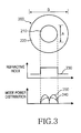
- FIG. 3 illustrates a view of a fluoride amplifying optical fiber known in the prior art.
- the fluoride amplifying optical fiber 200 comprises a core 210 disposed at a center of the fiber and a cladding 220 surrounding the core 210.
- a refractive index distribution curve 230 because there is a significant refractive index difference between the core 210 and the cladding 220, a problem occurs in that optical signals transmit in a multi-mode 240, 250.
- a core diameter A of the fluoride amplifying optical fiber 200 is reduced below 4 ⁇ m in order to transmit the optical signal in a single mode, coupling loss increases significantly when the fluoride amplifying optical fiber is coupled to the quartz amplifying optical fiber, the diameter of which is typically 8 ⁇ m.
- the amplifying optical fiber known in the prior art includes problems outlined below.
- the present invention provides an amplifying optical fiber that minimizes coupling loss by maintaining the diameter of a core at 8 ⁇ m and transmits light in a single mode.
- An embodiment of the present invention provides an amplifying optical fiber in which light-wave loss is not increased and mechanical strength is maintained even when an amplifying optical fiber is exposed to humidity.
- An embodiment of the present invention provides an amplifying optical fiber which improves fluorescence emitting efficiency and light amplification efficiency.
- An embodiment of the present invention provides an amplifying optical fiber in which light dispersion loss is reduced.
- An embodiment of the present invention provided a method for fabricating the amplifying optical fiber that achieves the above-stated objects.
- the present invention provides an amplifying optical fiber for amplifying an optical signal transmitted therethrough by stimulated emission, the amplifying optical fiber comprising: an inner core disposed at a center of said optical fiber and containing MX, GaS 3/2 and RE; an outer core surrounding said inner core and containing SiO 2 ; and a cladding surrounding said outer core and containing SiO 2 , wherein said M contained in MX is one component selected from the group consisting of Na, K, Rb and Cs; said X contained in MX is one component selected from the group consisting of F, Cl, Br, and I; and said RE is one component selected from the group consisting of Ce, Pr, Pm, Nd, Sm, Eu, Gd, Tb, Ho, Dy, Er, Tm and Yb.
- FIG. 4 shows an amplifying optical fiber according to the present invention.
- the amplifying optical fiber 300 comprises an inner core 310 disposed at the center of said amplifying optical fiber 300, an outer core 320 surrounding said inner core 310 and a cladding surrounding said outer core 320.
- the inner core has a diameter C in the range of 0.1 to 8 ⁇ m and may contain MX in the range of 5 to 67 mole %, GaS 3/2 in the range of 5 to 50 mole %, and RE in the range of 0.001 to 5 mole %. Also, it may further comprise one of the following: Ge in an amount greater than 0 and less than or equal to 33 mole%, As in an amount greater than 0 and less than or equal to 40 mole%, S in an amount greater than 0 and less than or equal to 67 mole % and LaS 3/2 in an amount greater than 0 and less than or equal to 50 mole %.
- M contained in said MX may be one component selected from a group consisting of Na, K, Rb, and Cs.
- X contained in said MX may be one component selected from a group consisting of F, Cl, Br and I.
- RE is a rare-earth element and may be one component selected from a group consisting of Ce, Pr, Pm, Nd, Sm, Eu, Gd, Tb, Ho, Dy, Er, Tm and Yb.
- the outer core 320 has a diameter D in the range of 2 to 10 ⁇ m and may comprise SiO 2 in the range of 30 to 100 mole %. Also, it may further comprise one of the following B 2 O 3 in an amount greater than 0 and less than or equal to 30 mole%, P 2 O 5 in an amount greater than 0 and less than or equal to 10 mole%, Al 2 O 3 in an amount greater than 0 and less than or equal to 10 mole % , GeO 2 in an amount greater than 0 and less than or equal to 30 mole %, PbO in an amount greater than 0 and less than or equal to 40 mole % and SiF 4 in an amount greater than 0 and less than or equal to 10 mole %.
- B 2 O 3 in an amount greater than 0 and less than or equal to 30 mole%
- P 2 O 5 in an amount greater than 0 and less than or equal to 10 mole%
- Al 2 O 3 in an amount greater than 0 and less than or equal to 10 mole %
- the cladding 330 has a diameter E in the range of 100 to 250 ⁇ m and may comprise SiO 2 in the range of 30 to 100 mole %. Also, it may further comprise one of following B 2 O 3 in an amount greater than 0 and less than or equal to 30 mole%, P 2 O 5 in an amount greater than 0 and less than or equal to 10 mole%, Al 2 O 3 in an amount greater than 0 and less than or equal to 10 mole % , GeO 2 in an amount greater than 0 and less than or equal to 30 mole %, PbO in an amount greater than 0 and less than or equal to 40 mole % and SiF 4 in an amount greater than 0 and less than or equal to 10 mole %.
- B 2 O 3 in an amount greater than 0 and less than or equal to 30 mole%
- P 2 O 5 in an amount greater than 0 and less than or equal to 10 mole%
- Al 2 O 3 in an amount greater than 0 and less than or equal to 10 mole %
- the difference ⁇ n of the refraction index between the outer core 320 and the cladding 330 is established to be in the range of 0.001 to 10 % and preferably to be below 2 %. Alternately, the difference ⁇ n of the refraction index between the inner core 310 and the outer core 320 is set to be below 2 %. In this case, the diameter C of the inner core 310 is set to be in the range of 1 to 8 ⁇ m.
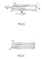
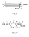
- FIGs. 5 to 9 illustrate explanatory views of a method for fabricating basic material for amplifying optical fiber according to the present invention.
- the method for fabricating basic material for amplifying optical fiber comprises steps of forming an outer core, supplying raw material, forming an inner core and collapsing a tube.
- the step of forming the outer core is a process for forming the outer core 430 on the inner wall of the quartz tube 420 for a cladding by means of the chemical vapor deposition method.
- a heating source such as an oxygen/hydrogen burner while material gas for the outer core is impregnated into the quartz tube 420.
- the quartz tube 410 is rotated and the heating source 410 moves along the longitudinal direction of the quartz tube 410.
- a high temperature zone is formed inside the quartz tube 420.
- the material gas passing through the high temperature zone produces reaction material, and the reaction material is deposited onto the inner wall of the quartz tube 420 to form the outer core 430.
- Chemical vapor deposition methods comprise MCVD (modified chemical vapor deposition), PECVD (plasma enhanced chemical vapor deposition).
- MCVD modified chemical vapor deposition
- PECVD plasma enhanced chemical vapor deposition
- FIG. 6 shows a quartz tube 420 with the outer core 430 formed on the inner wall thereof according to the above-mentioned step of forming the outer core.
- the above-mentioned step of supplying raw material is a process for supplying the raw material 440 for the inner core into the quartz tube 420.
- the raw material is produced in such a manner that raw material elements, such as, MX, GaS 3/2 , RE, etc., are melted in a separate container made of quartz material in order to prevent them from coming in contact with O 2 and then are rapidly cooled.
- FIG. 7 shows that the raw material 440 in the form of powder, grain or rod with a diameter in the range of 0.00 1 - 10 ⁇ m is supplied into said quartz tube 420.
- the above-mentioned step of forming the inner core is a process for forming the raw material 440 contained in said quartz tube 420.
- the outer surface of the quartz tube 420 is heated to a predetermined heating temperature as the quartz tube 420 is rotated in about its axis.
- the heating temperature must be lower than a softening point of the quartz tube and greater than a melting point of the raw material 440.
- the atmosphere gas that comprise at least two selected from the group consisting of He, Ne, Ar, Xe, N 2 , F 2 Cl 2 , Br 2 , I 2 , is supplied into the quartz tube 420.
- the above-mentioned step of collapsing a tube is a process for collapsing the quartz tube 420 to remove vacant space in the quartz tube 420.
- the quartz tube 420 is heated above the softening temperature thereof and the vacant space in the quartz tube 420 is kept at a lower pressure, so that there occurs a pressure difference between the interior and the exterior of the quartz tube 420.
- the quartz tube 420 collapses inward toward the axis of the tube its interior vacant space is removed, so that the basic material for an amplifying optical fiber is produced in a form of rod.
- the method proceeds to a step of elongating the amplifying optical fiber.
- the basic material for the amplifying optical fiber fabricated by the above-described method is loaded onto an apparatus for elongating the optical fiber so that one end of the optical fiber may be melted and elongated.
- the elongated optical fiber is coated with ultraviolet-hardening resin or thermosetting resin and its outer crust is formed by hardening said resin by ultraviolet rays or heating. The outer crust thus formed increases the mechanical strength of the amplifying optical fiber, protecting it against the external environment.
- the amplifying optical fiber according to the present invention may be diversely embodied depending on its components and many kinds of its embodiments are shown in Table 1 and Table 2.
- Table 1 shows figures representing components of the inner core in each embodiment.
- Table 2 shows figures representing formulation of the outer core and cladding commonly applied to each embodiment.
- Composition SiO 2 B 2 O 3 P 2 O 5 AL 2 O 3 GeO 2 PbO SiF 4 Outer core 70 17 3 2 2 5 1 Cladding 70 17 5 2 2 3 1
- Embodiment IV of Table 1 is detailed below by way of example only, along with the measured results with respect to that embodiment.
- an amplifying optical fiber 300 comprises an inner core 310, an outer core 320 and a cladding 330.
- the components of the amplifying optical fiber 300 are shown in Table 1 and Table 2.
- the inner core 310 has a diameter C of 0.6 ⁇ m and a refractive index of 1.58.
- the outer core 320 has a diameter D of 8 ⁇ m and a refractive index of 1.4590.
- the cladding 330 has a diameter E of 125 ⁇ m and a refractive index of 1.45701.
- the amplifying optical fiber 300 has a numerical aperture(NA) of 0.076, a mode field diameter (MFD) of 9.25 ⁇ m at the wavelength of 1.45 ⁇ m, and a coupling loss of 0.9 dB when coupled to a transmitting optical fiber.
- NA numerical aperture
- MFD mode field diameter
- FFD mode field diameter
- the amplifying optical fiber 300 has a transmitting loss of 0.13dB/m at a wavelength of 1.45 ⁇ m.
- a light signal with a wavelength of 1.45 ⁇ m transmits in a single mode 350.
- the cut-off wavelength in the single mode is 1.2 ⁇ m and bending loss is 0.2 dB/km at a wavelength of 1.65 ⁇ m.
- this amplifying optical fiber 300 has a transmission loss that is somewhat greater than the 0.1dB/m loss of the fluoride optical fiber known in the prior art, it is appropriate for purposes of use in an optical fiber amplifier or an optical fiber laser when considering that a length of optical fiber used in an optical fiber amplifier or an optical fiber laser is in a range of 20 - 40 m.
- the fluoride optical fiber of the prior art has problems in that only a mechanical coupling to a transmitting quartz optical fiber is possible, the coupling loss is greater than 1dB and that, due to high reproducibility, is not enough; the amplifying optical fiber 300 according to the present invention makes it possible to obtain high reproducibility and low coupling loss because a fusion splicing to the transmitting quartz optical fiber is possible.
- the inner core is protected by the cladding 330 and the outer core 320 made from chemically stabilized quartz glass even when the outer crust (not shown), i.e., the polymer coating layer is removed for coupling, O-H chemical bonding of the inner core 310 resulting from exterior humidity is kept to a minimum.
- the amplifying optical fiber 300 since the transmission of an optical signal is achieved mostly through the outer core 320 and the stimulated emission occurs only through the inner core 310, optical loss is minimized even in a state in which the inner core 310 is partially damaged by O-H chemical bonding.
- FIG. 10 illustrates diagrammatically a structure of an apparatus for measuring optical amplification gain
- FIG. 11 illustrates an optical amplification gain spectrum measured by the apparatus illustrated in FIG. 10.
- the apparatus comprises a wavelength variable type laser diode 510, first and second optical couplers 530 and 560, a pumping laser diode 570, a photodiode 540, first and second isolators 520 and 580, and a spectrum analyzer 590. Between the first and the second optical couplers 530 and 560, amplifying optical fiber 300 according to the present invention is disposed for coupling.
- the wavelength variable type laser diode 510 outputs an optical signal in a wavelength range of 1.45 to 1.5 ⁇ m and the pumping laser diode 570 produces a pumping light of 400 mW at a wavelength of 0.8 ⁇ m.
- the output of the optical signal measured by the photodiode 540 is -30dBm and the length of the amplifying optical fiber 300 is 20 m.
- the optical amplification gains above 30 dB are measured in a wavelength band of 60 nm in which gains are leveled. Accordingly, with the use of said amplifying optical fiber 300, it is possible to achieve the Tm 3+ -doped optical fiber amplifier (TDFA) for amplifying optical signals of the S band (corresponding to a wavelength range of 1.45 to 1.5 ⁇ m).
- TDFA Tm 3+ -doped optical fiber amplifier
- the amplifying optical fiber according to the present invention has an advantage in that it can further reduce the difference in refractive index between the outer core and the cladding compared to that of the prior art, so that the optical signal can emit in a single mode.
- the amplifying optical fiber according to the present invention has another advantage in that the optical loss due to an intrusion of humidity can be minimized because the inner core is protected by the outer core and the cladding made from chemically stabilized quartz.
Landscapes
- Physics & Mathematics (AREA)
- Chemical & Material Sciences (AREA)
- Optics & Photonics (AREA)
- Engineering & Computer Science (AREA)
- Materials Engineering (AREA)
- Chemical Kinetics & Catalysis (AREA)
- General Chemical & Material Sciences (AREA)
- Geochemistry & Mineralogy (AREA)
- Life Sciences & Earth Sciences (AREA)
- Organic Chemistry (AREA)
- Electromagnetism (AREA)
- Plasma & Fusion (AREA)
- General Physics & Mathematics (AREA)
- Glass Compositions (AREA)
- Lasers (AREA)
- Optical Fibers, Optical Fiber Cores, And Optical Fiber Bundles (AREA)
- Manufacture, Treatment Of Glass Fibers (AREA)
Applications Claiming Priority (2)
| Application Number | Priority Date | Filing Date | Title |
|---|---|---|---|
| KR2002051146 | 2002-08-28 | ||
| KR10-2002-0051146A KR100433909B1 (ko) | 2002-08-28 | 2002-08-28 | 증폭용 광섬유 및 그 제조 방법 |
Publications (2)
| Publication Number | Publication Date |
|---|---|
| EP1394909A2 true EP1394909A2 (fr) | 2004-03-03 |
| EP1394909A3 EP1394909A3 (fr) | 2005-05-04 |
Family
ID=31492904
Family Applications (1)
| Application Number | Title | Priority Date | Filing Date |
|---|---|---|---|
| EP03018798A Withdrawn EP1394909A3 (fr) | 2002-08-28 | 2003-08-28 | Fibre optique amplificatrice et méthode de fabrication |
Country Status (5)
| Country | Link |
|---|---|
| US (1) | US6987923B2 (fr) |
| EP (1) | EP1394909A3 (fr) |
| JP (1) | JP2004083411A (fr) |
| KR (1) | KR100433909B1 (fr) |
| CN (1) | CN1493893A (fr) |
Cited By (2)
| Publication number | Priority date | Publication date | Assignee | Title |
|---|---|---|---|---|
| DE102004013814A1 (de) * | 2004-03-20 | 2005-10-13 | B. Braun Medizintechnologie Gmbh | Verfahren zur Gestattung von Bedienereingaben an einem medizinischen Gerät |
| US7038844B2 (en) * | 2003-09-29 | 2006-05-02 | The Regents Of The University Of California | High power 938 nanometer fiber laser and amplifier |
Families Citing this family (15)
| Publication number | Priority date | Publication date | Assignee | Title |
|---|---|---|---|---|
| US6516124B2 (en) * | 2001-03-02 | 2003-02-04 | Optical Power Systems Incorporated | Fiber for enhanced energy absorption |
| US20030200771A1 (en) * | 2002-04-30 | 2003-10-30 | Burke Gerald E. | Method of manufacturing phosphosilicate optical fibers and optical fibers formed therefrom |
| US7046902B2 (en) * | 2003-09-30 | 2006-05-16 | Coractive High-Tech Inc. | Large mode field diameter optical fiber |
| US7088900B1 (en) * | 2005-04-14 | 2006-08-08 | Corning Incorporated | Alkali and fluorine doped optical fiber |
| JP2008078629A (ja) * | 2006-09-20 | 2008-04-03 | Imra America Inc | ファイバ・レーザおよびファイバ増幅器用の希土類がドープされ有効区域が大きい光ファイバ |
| JP5113400B2 (ja) * | 2007-02-08 | 2013-01-09 | 株式会社フジクラ | 光ファイバ、光ファイバ装置及びバンドルファイバ |
| US7805039B2 (en) * | 2007-05-04 | 2010-09-28 | Weatherford/Lamb, Inc. | Single mode optical fiber with improved bend performance |
| JP5329991B2 (ja) * | 2009-01-16 | 2013-10-30 | 三菱電線工業株式会社 | 希土類元素添加光ファイバ母材の製造方法 |
| CN104496173A (zh) * | 2014-12-15 | 2015-04-08 | 山东海富光子科技股份有限公司 | 用于高功率光纤激光器的硅酸盐全玻璃光纤的外包层玻璃 |
| JP7266525B2 (ja) * | 2017-01-19 | 2023-04-28 | コーニング インコーポレイテッド | ハイブリッドコア光ファイバを採用した分布型ファイバセンサ及びシステム |
| CN109052943A (zh) * | 2018-09-28 | 2018-12-21 | 镇江微芯光子科技有限公司 | 一种高稳定性的玻璃光纤 |
| US20200325300A1 (en) * | 2019-04-12 | 2020-10-15 | The Government Of The United States Of America, As Represented By The Secretary Of The Navy | Fabrication of polymer nanocomposites for use as fiber laser claddings |
| US20220009027A1 (en) * | 2020-07-07 | 2022-01-13 | Panasonic Intellectual Property Management Co. Ltd | Step-core fiber structures and methods for altering beam shape and intensity |
| CN115304266B (zh) * | 2022-10-11 | 2023-01-20 | 武汉长进激光技术有限公司 | 一种抗辐照保偏铒镱共掺光纤及其制备方法与应用 |
| CN116924687A (zh) * | 2023-07-24 | 2023-10-24 | 武汉安扬激光技术股份有限公司 | 一种可调控热光系数的稀土掺杂光纤及其制备方法和应用 |
Family Cites Families (15)
| Publication number | Priority date | Publication date | Assignee | Title |
|---|---|---|---|---|
| JP2857218B2 (ja) | 1990-04-20 | 1999-02-17 | 日本電信電話株式会社 | ファイバレーザ媒質およびこれを用いた光増幅器 |
| US5309452B1 (en) | 1992-01-31 | 1998-01-20 | Univ Rutgers | Praseodymium laser system |
| JP3228451B2 (ja) * | 1994-01-26 | 2001-11-12 | 日本電信電話株式会社 | 光ファイバ増幅器 |
| US5530709A (en) | 1994-09-06 | 1996-06-25 | Sdl, Inc. | Double-clad upconversion fiber laser |
| KR100195338B1 (ko) * | 1995-08-04 | 1999-06-15 | 권문구 | 탄소막이 증착튜브 내벽에 증착된 고강도 광섬유 및 그 제조방법 |
| EP0787694B1 (fr) | 1996-01-30 | 1999-04-21 | Nippon Telegraph And Telephone Corporation | Fibre de verre fluoré |
| KR0167132B1 (ko) * | 1996-03-30 | 1999-01-15 | 윤종용 | 어븀 첨가 광섬유의 제조 방법 및 장치 |
| EP1015396A1 (fr) | 1997-06-23 | 2000-07-05 | Corning Incorporated | Composition pour guide d'onde optique et procede de production de filament continu enrobe |
| JP3860647B2 (ja) * | 1997-08-04 | 2006-12-20 | 日立電線株式会社 | 希土類元素添加光ファイバおよびその製造方法、およびその希土類元素添加光ファイバを用いた光ファイバ増幅器 |
| KR100319296B1 (ko) * | 1998-10-13 | 2002-04-22 | 윤종용 | 광증폭기용광섬유 |
| JP2000252558A (ja) * | 1999-02-26 | 2000-09-14 | Sumitomo Electric Ind Ltd | 光増幅用光ファイバおよびその製造方法 |
| US6385384B1 (en) * | 1999-03-15 | 2002-05-07 | Corning Incorporated | Glasses containing rare earth fluorides |
| US6194334B1 (en) * | 1999-06-18 | 2001-02-27 | Corning Incorporated | Tellurite glasses and optical components |
| WO2003033422A1 (fr) * | 2001-10-15 | 2003-04-24 | The Furukawa Electric Co., Ltd. | Procede de production de verre dope aux elements du groupe des terres rares et fibre destinee a l'amplification optique utilisant un tel verre |
| KR100427446B1 (ko) * | 2002-05-13 | 2004-04-17 | 엘지전선 주식회사 | 광증폭기용 광섬유 및 제조방법 |
-
2002
- 2002-08-28 KR KR10-2002-0051146A patent/KR100433909B1/ko not_active Expired - Fee Related
-
2003
- 2003-08-12 US US10/638,985 patent/US6987923B2/en not_active Expired - Fee Related
- 2003-08-28 JP JP2003304157A patent/JP2004083411A/ja not_active Abandoned
- 2003-08-28 CN CNA031553923A patent/CN1493893A/zh active Pending
- 2003-08-28 EP EP03018798A patent/EP1394909A3/fr not_active Withdrawn
Cited By (2)
| Publication number | Priority date | Publication date | Assignee | Title |
|---|---|---|---|---|
| US7038844B2 (en) * | 2003-09-29 | 2006-05-02 | The Regents Of The University Of California | High power 938 nanometer fiber laser and amplifier |
| DE102004013814A1 (de) * | 2004-03-20 | 2005-10-13 | B. Braun Medizintechnologie Gmbh | Verfahren zur Gestattung von Bedienereingaben an einem medizinischen Gerät |
Also Published As
| Publication number | Publication date |
|---|---|
| US6987923B2 (en) | 2006-01-17 |
| KR100433909B1 (ko) | 2004-06-04 |
| US20040042759A1 (en) | 2004-03-04 |
| EP1394909A3 (fr) | 2005-05-04 |
| JP2004083411A (ja) | 2004-03-18 |
| KR20040019561A (ko) | 2004-03-06 |
| CN1493893A (zh) | 2004-05-05 |
Similar Documents
| Publication | Publication Date | Title |
|---|---|---|
| US6987923B2 (en) | Amplifying optical fiber and method for fabricating the same | |
| CA2056925C (fr) | Optocoupleur et amplificateur a fibres optiques | |
| US8958674B2 (en) | Amplifying optical fiber and production method | |
| US8259389B2 (en) | Amplifying optical fiber and method of manufacturing | |
| US6128430A (en) | Composition for optical waveguide article and method for making continuous clad filament | |
| US9162917B2 (en) | Rare-earth-doped amplifying optical fiber | |
| US8279900B2 (en) | Mode-locked two-micron fiber lasers | |
| US20130336343A1 (en) | Optical fiber, optical fiber laser and optical fiber amplifier, and method of manufacturing optical fiber | |
| CN1044748C (zh) | 光纤耦合器及放大器 | |
| EP1927167B1 (fr) | Procedes de fabrication d'une fibre optique amplificatrice fonctionnant sur une longueur d'onde comprise entre 1000 et 1700 nm | |
| US4881793A (en) | Optical fibre attenuators and method for making same | |
| JP3730775B2 (ja) | テルライトガラス、該テルライトガラスを用いた光増幅器および光源 | |
| JPH09159846A (ja) | 希土類元素添加マルチコアファイバ及びその製造方法 | |
| JPH11142672A (ja) | シリカベースの光ファイバを有する物品 | |
| JPH07109920B2 (ja) | エルビウムがドープされた光ファイバーを有する通信システム | |
| CA2276997C (fr) | Fibre optique pour un amplificateur optique et amplificateur de fibre optique | |
| GB2596483A (en) | Fiber laser pump reflector | |
| US6955774B2 (en) | Plastic optical fiber and method for producing the same | |
| US20020191902A1 (en) | Compact optical fiber amplifier module | |
| US5805332A (en) | Optical fiber amplifier | |
| JPH05249329A (ja) | 高入力光ファイバ及びその母材の製造方法 | |
| CN102073093B (zh) | 一种高衰减光纤及其制造方法 | |
| JP2005037959A (ja) | テルライトガラス、該テルライトガラスを用いた光増幅器および光源 | |
| US20250333349A1 (en) | Aluminosilicate Glasses with High Er3+ Concentration and High Quantum Yield | |
| JP4255077B2 (ja) | 光増幅器および光源 |
Legal Events
| Date | Code | Title | Description |
|---|---|---|---|
| PUAI | Public reference made under article 153(3) epc to a published international application that has entered the european phase |
Free format text: ORIGINAL CODE: 0009012 |
|
| 17P | Request for examination filed |
Effective date: 20030828 |
|
| AK | Designated contracting states |
Kind code of ref document: A2 Designated state(s): AT BE BG CH CY CZ DE DK EE ES FI FR GB GR HU IE IT LI LU MC NL PT RO SE SI SK TR |
|
| AX | Request for extension of the european patent |
Extension state: AL LT LV MK |
|
| PUAL | Search report despatched |
Free format text: ORIGINAL CODE: 0009013 |
|
| AK | Designated contracting states |
Kind code of ref document: A3 Designated state(s): AT BE BG CH CY CZ DE DK EE ES FI FR GB GR HU IE IT LI LU MC NL PT RO SE SI SK TR |
|
| AX | Request for extension of the european patent |
Extension state: AL LT LV MK |
|
| AKX | Designation fees paid |
Designated state(s): DE FR GB |
|
| STAA | Information on the status of an ep patent application or granted ep patent |
Free format text: STATUS: THE APPLICATION HAS BEEN WITHDRAWN |
|
| 18W | Application withdrawn |
Effective date: 20060310 |