EP1395105A2 - Komponentplazierungsmaschine - Google Patents
Komponentplazierungsmaschine Download PDFInfo
- Publication number
- EP1395105A2 EP1395105A2 EP03255397A EP03255397A EP1395105A2 EP 1395105 A2 EP1395105 A2 EP 1395105A2 EP 03255397 A EP03255397 A EP 03255397A EP 03255397 A EP03255397 A EP 03255397A EP 1395105 A2 EP1395105 A2 EP 1395105A2
- Authority
- EP
- European Patent Office
- Prior art keywords
- connecting shaft
- nozzle
- shaft
- nozzle connecting
- component
- Prior art date
- Legal status (The legal status is an assumption and is not a legal conclusion. Google has not performed a legal analysis and makes no representation as to the accuracy of the status listed.)
- Granted
Links
Images


Classifications
-
- B—PERFORMING OPERATIONS; TRANSPORTING
- B23—MACHINE TOOLS; METAL-WORKING NOT OTHERWISE PROVIDED FOR
- B23P—METAL-WORKING NOT OTHERWISE PROVIDED FOR; COMBINED OPERATIONS; UNIVERSAL MACHINE TOOLS
- B23P21/00—Machines for assembling a multiplicity of different parts to compose units, with or without preceding or subsequent working of such parts, e.g. with program control
-
- H—ELECTRICITY
- H05—ELECTRIC TECHNIQUES NOT OTHERWISE PROVIDED FOR
- H05K—PRINTED CIRCUITS; CASINGS OR CONSTRUCTIONAL DETAILS OF ELECTRIC APPARATUS; MANUFACTURE OF ASSEMBLAGES OF ELECTRICAL COMPONENTS
- H05K13/00—Apparatus or processes specially adapted for manufacturing or adjusting assemblages of electric components
- H05K13/04—Mounting of components, e.g. of leadless components
- H05K13/0404—Pick-and-place heads or apparatus, e.g. with jaws
- H05K13/0408—Incorporating a pick-up tool
- H05K13/0409—Sucking devices
-
- H—ELECTRICITY
- H05—ELECTRIC TECHNIQUES NOT OTHERWISE PROVIDED FOR
- H05K—PRINTED CIRCUITS; CASINGS OR CONSTRUCTIONAL DETAILS OF ELECTRIC APPARATUS; MANUFACTURE OF ASSEMBLAGES OF ELECTRICAL COMPONENTS
- H05K13/00—Apparatus or processes specially adapted for manufacturing or adjusting assemblages of electric components
- H05K13/04—Mounting of components, e.g. of leadless components
- H05K13/0404—Pick-and-place heads or apparatus, e.g. with jaws
- H05K13/0413—Pick-and-place heads or apparatus, e.g. with jaws with orientation of the component while holding it; Drive mechanisms for gripping tools, e.g. lifting, lowering or turning of gripping tools
-
- Y—GENERAL TAGGING OF NEW TECHNOLOGICAL DEVELOPMENTS; GENERAL TAGGING OF CROSS-SECTIONAL TECHNOLOGIES SPANNING OVER SEVERAL SECTIONS OF THE IPC; TECHNICAL SUBJECTS COVERED BY FORMER USPC CROSS-REFERENCE ART COLLECTIONS [XRACs] AND DIGESTS
- Y10—TECHNICAL SUBJECTS COVERED BY FORMER USPC
- Y10T—TECHNICAL SUBJECTS COVERED BY FORMER US CLASSIFICATION
- Y10T29/00—Metal working
- Y10T29/53—Means to assemble or disassemble
- Y10T29/5313—Means to assemble electrical device
- Y10T29/53174—Means to fasten electrical component to wiring board, base, or substrate
- Y10T29/53178—Chip component
Definitions
- the present invention relates to a component-placing apparatus having a suction head for mounting an electronic component on a board or the like, or for assembling electronic components.
- a component-placing apparatus having a suction head has been used for mounting an electronic component such as a semiconductor chip and/or a piezoelectric component on a board such as a printed circuit board.
- a nozzle head has been proposed in which a rotary motor for rotating a nozzle for applying suction to an electronic component and a cylindrical linear motor for vertically moving the nozzle, are disposed coaxially with the nozzle, such that moving parts of these motors rotate or move vertically while being integral with the nozzle.
- a semiconductor-mounting apparatus in which a suction nozzle, a pressure shaft which is movable vertically and rotatable and has the suction nozzle at the bottom thereof, an ultrasonic motor for turning the pressure shaft, and a voice coil motor for moving the pressure shaft in the vertical direction are disposed such that the pressure shaft extends through the voice coil motor and the ultrasonic motor.
- the voice coil motor when the voice coil motor is used as the cylindrical linear motor, since the shaft extends through the center of the voice coil motor, the central part of the motor cannot be used as a core; hence, the voice coil motor does not effectively generate a thrust force. Accordingly, the size of the voice coil motor must unavoidably be large. Also, the rotary motor is rotated together with a yoke and a casing of the voice coil motor, thereby causing problems of large inertia and large size of the rotary motor. In addition, when a moving coil of the voice coil motor rotates together with the shaft, feeding the moving coil with current is difficult.
- a component-placing apparatus for driving a suction nozzle in the rotational ( ⁇ ) and vertical (Z) directions for applying suction to a component, comprising: a rotary actuator; a linear actuator comprising a stator connected to a stator of the rotary actuator such that these stators are immovable relative to each other; a spline shaft connected to a rotating shaft of the rotary actuator; a nozzle connecting shaft connected to the spline shaft for being allowed to move only rectilinearly in the longitudinal direction of the spline shaft relative to the spline shaft and having the suction nozzle disposed at the bottom thereof; a hollow holder encircling the nozzle connecting shaft with rotary bearings being interposed therebetween which allow the nozzle connecting shaft to rotate with respect to the spline shaft and connected for being driven by a mover of the linear actuator; and a linear guide for guiding the hollow holder relative to the stators of the actuators so as to be rectilinear
- a functional equivalent may be substituted for the spline shaft.
- the invention also provides a component-placing apparatus for driving a suction nozzle in the rotational ( ⁇ ) and vertical (Z) directions for applying suction to a component, comprising: a rotary actuator having a rotating shaft; a linear actuator comprising a stator connected to a stator of the rotary actuator such that these stators are immovable relative to each other; a nozzle connecting shaft having the suction nozzle disposed at the bottom thereof; the nozzle connecting shaft being connected to the rotating shaft by a coupling which allows the nozzle connecting shaft to move only rectilinearly in the longitudinal direction of the rotating shaft, relative to the rotating shaft; a hollow holder encircling the nozzle connecting shaft with rotary bearings being interposed therebetween which allow the nozzle connecting shaft to rotate and connected for being driven by a mover of the linear actuator; and a linear guide for guiding the hollow holder relative to the stators of the actuators so as to be rectilinearly movable parallel to the rotating shaft.
- Embodiments of the invention may provide a component-placing apparatus having a linear actuator and a rotary actuator which are small in size which precisely position a component at high speed in the direction of the Z-axis and about the ⁇ -axis.
- the rotation of the rotary actuator is transmitted to the nozzle connecting shaft through the spline shaft.
- the nozzle connecting shaft having the suction nozzle disposed at its bottom is rectilinearly movable relative to the spline shaft.
- the hollow holder rotatably holding the nozzle connecting shaft is connected to the mover of the linear actuator.
- the nozzle connecting shaft and the spline shaft are movable in the axial direction, the rotational movement of the spline shaft can be transmitted to the nozzle connecting shaft regardless of the position at which the nozzle connecting shaft lies. Accordingly, the nozzle connecting shaft, and resultantly the suction nozzle, can be vertically moved to a desired position and turned -to a desired orientation.
- the stators of the linear actuator and the rotary actuator can be mutually fixed and thus are not required to drive each other. Accordingly, the mass of the vertically driven part and the inertia of the rotating part of the component-placing apparatus can be reduced, and thus a required thrust force of each actuator can be reduced, whereby both the rotary actuator and the linear actuator can be downsized.
- the actuators directly drive the nozzle both in the Z-axis direction and about the ⁇ -axis without an indirect transmission mechanism being interposed therebetween, a component can be precisely placed at high speed. Further, although the suction nozzle is radially shifted relative to the axis of the linear actuator, the nozzle is prevented from tilting due to its own weight, since the hollow holder is guided by the linear guide, thereby achieving a precise pick-and-place operation.
- the linear actuator since no shafts extend through the centers of the linear actuator and the rotary actuator, for example, a commercially available, compact servomotor can be used as the rotary actuator. Also, the central part of the linear actuator can be used as a core, whereby the linear actuator can effectively generate a thrust force. As a result, when a voice coil motor is used as the linear actuator, the size of a magnetic circuit of the voice coil motor can be reduced. In this case, since the moving coil of the voice coil motor moves only reciprocally and is not required to rotate, the moving coil can be easily fed with current.
- the stators of the rotary actuator and the linear actuator are fixed to a moving head of a drive mechanism driven in the X- and Y- directions.
- the component-placing apparatus can be independently driven in the X- and Y-directions by the drive mechanism, about the ⁇ -axis by the rotary actuator, and in the Z-direction by the linear actuator, respectively.
- a component can be precisely placed.
- the mover and the stator of the linear actuator have a return spring disposed therebetween for urging the mover upwards with its spring force which is slightly greater than the sum of the weight load of a moving part of the apparatus including the mover, the suction nozzle, and the nozzle connecting shaft, and a sliding frictional force generated between the linear guide and the spline shaft.
- the suction nozzle When the suction nozzle is vertically moved by driving the linear actuator, the suction nozzle drops when current to the linear actuator is shut off, due to the weight of the moving part including the suction nozzle.
- the return spring prevents this dropping.
- the linear actuator consumes a large amount of power in order to move the suction nozzle down.
- the hollow holder and the nozzle connecting shaft have an effectively sealed, or preferably a hermetically sealed, airtight chamber formed in a cylindrical space therebetween; the nozzle connecting shaft have an air passage formed therein for transmitting a pressure medium such as air in the airtight chamber to the suction nozzle; an air port in communication with the airtight chamber be formed in the outer surface of the hollow holder, and the air port be connected to a vacuum suction apparatus.
- the vacuum suction apparatus and the suction nozzle are required to be connected.
- the vacuum suction apparatus can be directly connected to the suction nozzle with an air hose being interposed therebetween, since the suction nozzle moves vertically and rotationally, there is a possibility that the hose is twisted or causes an operational resistance against the suction nozzle.
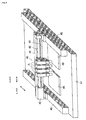
- Figs. 1 to 4 show a component-placing head (i.e., a component-placing apparatus) according to an embodiment of the present invention.
- a component-placing head i.e., a component-placing apparatus
- an electronic component P and a board B are referred to as a component and a fixing surface, respectively.
- a component-placing head A includes a supporting plate 1 fixed to a head of an X-Y robot or the like, a voice coil motor 2 as an example of a linear actuator having a stator (yoke) 3 fixed on the under surface of the supporting plate 1, and a servomotor 20 as an example of a rotary actuator having a stator 21 fixed on the upper surface of the supporting plate 1.
- the voice coil motor 2 is fixed on the lower surface of the supporting plate 1 and formed by the yoke 3 having an outer yoke 3a and a center yoke 3b, a magnet 4 fixed on the inner surface of the outer yoke 3a, a bobbin 5 inserted in the yoke 3 so as to be vertically movable, a coil 6 wound around the bobbin 5, and so forth.
- the coil 6 lies overlapping with the magnet 4 in the axial direction.
- the magnet 4 and the coil 6 are respectively disposed on the stationary and moving sides; on the other hand, the coil 6 and the magnet 4 may be respectively disposed on the stationary and moving sides.
- the bobbin 5 has a horizontal portion 7a of an approximately L-shaped connecting member 7 fixed on the bottom surface thereof, and a vertical portion 7b of the connecting member 7 protrudes axially parallel to the yoke 3, having a guide block 10 fixed on one side surface thereof.
- the guide block 10 is guided by a guide rail 9 fixed on the outer surface of the yoke 3 so as to be movable only in the vertical direction so that the guide rail 9 and the guide block 10 constitute a linear guide 8.
- the connecting member 7 has a hollow holder 30, which will be described later, fixed on the other side surface of the vertical portion 7b. Thus, the hollow holder 30 performs a precise and smooth linear motion relative to the yoke 3.
- the connecting member 7 and the supporting plate 1 have a return spring 11 interposed therebetween which is designed so as to return the bobbin 5 acting as a mover of the voice coil motor 2 to its top position when the power is off.
- the tensile force of the return spring 11 is set slightly greater than the sum of the weight load of a moving part including the bobbin 5, the coil 6, a suction nozzle 35, and a nozzle connecting shaft 26, which will be both described later, and a sliding frictional force generated between the linear guide 8 and a ball spline shaft 24, which will be described later.
- the return spring 11 is not limited to a tensile spring and may be a compression spring.
- the yoke 3 In order to detect the vertical movement of the voice coil motor 2, the yoke 3 has a linear encoder 12 fixed thereon, and the connecting member 7 has a linear scale 13 fixed thereon. By feeding back a signal of the linear encoder 12, the suction nozzle 35 can be controlled so as to lie at a desired vertical position.
- the servomotor 20 has an encoder integrated therein and can control the component-placing head so as to lie at a desired rotational position by feeding back a signal of the encoder.
- the servomotor 20 has a rotating shaft 22 extending downwards with the supporting plate 1 being interposed therebetween, and the rotating shaft 22 has the ball spline shaft 24 connected thereto with a coupling 23 being interposed therebetween.
- the ball spline shaft 24 is combined with a ball spline nut 25, to which the top of the nozzle connecting shaft 26 is fixed.
- the nozzle connecting shaft 26 rotates integrally with the ball spline shaft 24, it can move freely in the axial direction relative to the ball spline shaft 24 since its vertical movement is set free between the ball spline shaft 24 and the ball spline nut 25.
- the yoke 3 may have a stopper (not shown) on the surface thereof for limiting the moving range of the guide block 10 so as to prevent the ball spline nut 25 from being pulled out from the ball spline shaft 24.
- the nozzle connecting shaft 26 extends through the hollow holder 30, and the hollow holder 30 and the nozzle connecting shaft 26 are connected to each other at the upper and lower portions thereof by bearings (rotary bearings) 31 with flanges.
- bearings rotary bearings
- the nozzle connecting shaft 26 is rotatable relative to the holder 30 but is vertically immovable relative to the same.
- the voice coil motor 2 is activated, the holder 30 and the nozzle connecting shaft 26 move vertically in one united body. Since the lower bearing 31 is fixed by a nut 32 screwed together with a screw formed at the lower portion of the nozzle connecting shaft 26, the play in the vertical direction between the nozzle connecting shaft 26 and the holder 30 is minimized.
- seals 33 are disposed between the two bearings 31 so as to provide an airtight chamber 34 therebetween, thereby preventing air from flowing into and out from the chamber 34 in the vertical direction.
- the seals 33 in this embodiment are each a combination seal of a rubber ring 33a such as an O-ring and a resin ring 33b composed of a tetrafluoroethylene resin and disposed on the inner periphery of the rubber ring 33a.
- two seal stoppers 37 are provided.
- the nozzle connecting shaft 26 has a hollow structure so as to provide an air passage 27 therein having an open bottom. Also, the nozzle connecting shaft 26 has an air hole 28 formed therein for communication between the internal air passage 27 and the external airtight chamber 34.
- the nozzle connecting shaft 26 has the suction nozzle 35 fixed at the bottom thereof.
- the suction nozzle 35 has a shock-absorbing mechanism (not shown) with a spring built therein so as to absorb a shock against the electronic component P at the time of applying suction to it and mounting it on the board B.
- the hollow holder 30 has an air port 36 formed in the outer surface thereof for communication to the airtight chamber 34, to which an air hose (not shown) is connected. The air hose is connected to a vacuum suction apparatus (not shown). Thus, a suction pressure is transmitted to the suction nozzle 35 through the air port 36, the airtight chamber 34, the air hole 28, and the air passage 27.
- Fig. 3 illustrates a state in which the voice coil motor 2 is switched off and the moving part including the suction nozzle 35 is raised to its top position (original position) by the spring force of the return spring 11.
- the coil 6 receives a thrust force in the axial direction in proportion to the product of a magnetic density, an amount of current, and a conductor length of the coil; hence, as shown in Fig. 4, the holder 30 connected to the coil 6 with the connecting member 7 being interposed therebetween also moves downwards (i.e., downwards in the Z-axis direction as indicated by the arrow shown in Fig. 4).
- the nozzle connecting shaft 26 Since the nozzle connecting shaft 26 is held to the holder 30 with the bearings 31 being interposed therebetween so as to be rotatable but immovable in the axial direction, the nozzle connecting shaft 26 can move downwards while maintaining the ball spline shaft 24 and the ball spline nut 25 in engagement with each other. As a result, the suction nozzle 35 fixed to the bottom of the nozzle connecting shaft 26 moves downwards so as to mount the electronic component P held by suction at the end thereof on the board B.
- the servomotor 20 For adjusting the orientation of the electronic component P around the ⁇ -axis (i.e., the rotating axis of the component-placing head A) in order to mount the electronic component P on the board B, the servomotor 20 is driven so as to turn the electronic component P to a proper orientation.
- the rotation of the servomotor 20 is transmitted to the nozzle connecting shaft 26 through the ball spline shaft 24 and the ball spline nut 25, and the bearings 31 prevent the rotating force of the servomotor 20 from being transmitted to the holder 30, the nozzle connecting shaft 26 can be rotated with a small torque. As a result, the orientation of the electronic component P can be precisely adjusted.
- the component-placing head A has the servomotor 20, the nozzle connecting shaft 26, and the suction nozzle 35, all disposed coaxially with each other, and directly transmits the torque of the servomotor 20 to the suction nozzle 35.
- the servomotor 20 can be made small in size and also the positioning of the electronic component P around the ⁇ -axis can be precisely performed.
- the voice coil motor 2 vertically drives only the nozzle connecting shaft 26 and the holder 30 and is not required to vertically drive the servomotor 20 and the ball spline shaft 24.
- the voice coil motor 2 is only required to produce a relatively small thrust force and hence can be made small in size.
- the axis of the voice coil motor 2 is radially shifted relative to the axis of the nozzle connecting shaft 26 and the suction nozzle 35, the suction nozzle 35 is not likely to be tilted, since the holder 30 holding the nozzle connecting shaft 26 is guided to move only in the vertical direction by the linear guide 8, thereby achieving a precise pick-and-place operation of the component-placing head A.
- Fig. 5 illustrates an example of a mounting apparatus using the above-described component-placing head A.
- This mounting apparatus has a multi-head 40 formed by four units of the component-placing heads A.
- the multi-head 40 is supported by a Y-axis beam 41, which includes a servomotor 42, a ball screw 43, and a linear guide 44, both ends of which are supported by two linear motors 45 and 46 driven in the X-axis direction.
- the Y-axis beam 41 and the linear motors 45 and 46 are subjected to a feedback control using a linear scale and a linear encoder (both not shown) so that the multi-head 40 is positioned at a desired position on an X-Y plane lying perpendicular to the Z-axis.
- the linear motors 45 and 46 are supported by a mounting table 47, on which a feeding board 48 and a placing board 49 are arranged.
- each nozzle of the component-placing heads A can be independently controlled in the direction of the Z-axis and about the ⁇ -axis in concert with the movements of the Y-axis beam 41 and the linear motors 45 and 46 along the X-and Y-axes.
- an electronic component can be precisely transferred from the feeding board 48 to the placing board 49.
- a voice coil motor 2 is used as the linear actuator by way of example in the above-described embodiment, a combination of a servomotor, a ball screw, and a linear guide, or an air cylinder, may be used in place of the voice coil motor, for example.
- the linear guide of the linear actuator can be also used as a linear guide for guiding the hollow holder so as to be rectilinearly movable parallel to the spline shaft.
Landscapes
- Engineering & Computer Science (AREA)
- Manufacturing & Machinery (AREA)
- Microelectronics & Electronic Packaging (AREA)
- Mechanical Engineering (AREA)
- Supply And Installment Of Electrical Components (AREA)
- Manipulator (AREA)
- Automatic Assembly (AREA)
- Agricultural Chemicals And Associated Chemicals (AREA)
Applications Claiming Priority (2)
| Application Number | Priority Date | Filing Date | Title |
|---|---|---|---|
| JP2002250110 | 2002-08-29 | ||
| JP2002250110A JP3772808B2 (ja) | 2002-08-29 | 2002-08-29 | 部品装着装置 |
Publications (3)
| Publication Number | Publication Date |
|---|---|
| EP1395105A2 true EP1395105A2 (de) | 2004-03-03 |
| EP1395105A3 EP1395105A3 (de) | 2010-04-28 |
| EP1395105B1 EP1395105B1 (de) | 2011-03-02 |
Family
ID=31492595
Family Applications (1)
| Application Number | Title | Priority Date | Filing Date |
|---|---|---|---|
| EP03255397A Expired - Lifetime EP1395105B1 (de) | 2002-08-29 | 2003-08-29 | Komponentplazierungsmaschine |
Country Status (7)
| Country | Link |
|---|---|
| US (1) | US6851914B2 (de) |
| EP (1) | EP1395105B1 (de) |
| JP (1) | JP3772808B2 (de) |
| KR (1) | KR100560070B1 (de) |
| CN (1) | CN1266993C (de) |
| AT (1) | ATE500723T1 (de) |
| DE (1) | DE60336195D1 (de) |
Cited By (8)
| Publication number | Priority date | Publication date | Assignee | Title |
|---|---|---|---|---|
| EP1734802A3 (de) * | 2005-06-16 | 2007-12-05 | Siemens Aktiengesellschaft | Bestückkopf für einen Bestückautomaten zum Bestücken von Substraten mit elektrischen Bauteilen |
| CN1926937B (zh) * | 2004-04-23 | 2010-09-08 | 松下电器产业株式会社 | 线性驱动机构和采用该线性驱动机构的电子元件安装装置 |
| CN101636071B (zh) * | 2008-07-25 | 2014-07-09 | Juki株式会社 | 电子部件搭载头 |
| EP2755308A4 (de) * | 2011-09-07 | 2015-08-12 | Thk Co Ltd | Linearmotor und steuerverfahren |
| EP3307042A4 (de) * | 2015-05-27 | 2018-05-02 | Fuji Machine Mfg. Co., Ltd. | Komponentenmontagekopf und saugdüsenanordnung zur verwendung darin |
| EP3340760A4 (de) * | 2015-08-20 | 2018-08-08 | Fuji Machine Mfg. Co., Ltd. | Komponentenmontagevorrichtung |
| CN112171267A (zh) * | 2020-10-12 | 2021-01-05 | 乐清市海马电子有限公司 | 一种用于生产压电电子的流水线及其生产工艺 |
| CN112171266A (zh) * | 2020-10-12 | 2021-01-05 | 乐清市海马电子有限公司 | 一种压电电子点火装置半成品组装设备及其生产工艺 |
Families Citing this family (44)
| Publication number | Priority date | Publication date | Assignee | Title |
|---|---|---|---|---|
| DE10236626A1 (de) * | 2002-08-09 | 2004-02-19 | Siemens Ag | Vorrichtung zum selektiven Bewegen von Haltevorrichtungen und Bestückkopf zum Transportieren von Bauelementen |
| US20050056215A1 (en) * | 2003-03-11 | 2005-03-17 | Shibaura Mechantronics Corporation | Apparatus for applying paste and method of applying paste |
| CH696103A5 (de) * | 2003-06-06 | 2006-12-15 | Esec Trading Sa | Halbleiter-Montageeinrichtung. |
| JP4643185B2 (ja) * | 2004-07-05 | 2011-03-02 | リンテック株式会社 | 移載装置 |
| JP4813056B2 (ja) * | 2004-07-29 | 2011-11-09 | パナソニック株式会社 | 部品実装用実装ヘッド、及び該実装ヘッドを備える部品実装装置 |
| US7484782B2 (en) * | 2005-08-26 | 2009-02-03 | Intellepro, Inc. | Multi-axis pick and place assembly |
| US20070089554A1 (en) * | 2005-10-21 | 2007-04-26 | Gieskes Koenraad A | Tetrahedron rack and pinion drive |
| US7471019B2 (en) * | 2005-12-30 | 2008-12-30 | The Gillette Company | High speed assembly actuator |
| JP4208155B2 (ja) * | 2006-03-27 | 2009-01-14 | パナソニック株式会社 | 実装ヘッド、および電子部品実装装置 |
| US20080003092A1 (en) * | 2006-06-30 | 2008-01-03 | Petar Baclija | Rotary union connection |
| KR100909426B1 (ko) * | 2006-10-17 | 2009-07-24 | 엘에스산전 주식회사 | 액츄에이터 |
| US8550523B2 (en) * | 2007-06-22 | 2013-10-08 | Data I/O Corporation | Pick and place system |
| JP5151306B2 (ja) * | 2007-08-09 | 2013-02-27 | 富士通株式会社 | 部品供給装置及びその方法 |
| JP4705118B2 (ja) * | 2008-01-11 | 2011-06-22 | ヤマハ発動機株式会社 | 多軸リニアモータ及び部品移載装置 |
| JP4997124B2 (ja) * | 2008-01-21 | 2012-08-08 | 株式会社日立ハイテクインスツルメンツ | 電子部品装着ヘッド及び電子部品装着装置 |
| JP5359803B2 (ja) * | 2008-12-25 | 2013-12-04 | 株式会社村田製作所 | 部品装着装置および多部品装着装置 |
| IT1393030B1 (it) * | 2009-03-11 | 2012-04-11 | Gimatic Spa | Dispositivo di supporto per organi prensili |
| KR101610272B1 (ko) * | 2009-04-15 | 2016-04-08 | 한화테크윈 주식회사 | 진공 노즐 제어 장치 및 이를 갖는 부품 실장기용 헤드 어셈블리 |
| JP5287741B2 (ja) * | 2010-01-21 | 2013-09-11 | 富士通株式会社 | 部品のマウンタ装置及び部品のマウント方法 |
| JP5689646B2 (ja) * | 2010-10-26 | 2015-03-25 | Juki株式会社 | 電子部品実装装置 |
| JP5129371B1 (ja) * | 2011-07-27 | 2013-01-30 | ファナック株式会社 | 重量計測機能付き吸着式ロボットハンド |
| JP5875376B2 (ja) | 2012-01-12 | 2016-03-02 | ヤマハ発動機株式会社 | 吸着ノズル昇降用リニアモータおよび電子部品実装装置 |
| JP5747168B2 (ja) * | 2012-03-12 | 2015-07-08 | パナソニックIpマネジメント株式会社 | 装着ヘッド及び部品装着装置 |
| US8920103B2 (en) * | 2012-05-10 | 2014-12-30 | Varian Semiconductor Equipment Associates, Inc. | Multi-cell rotary end effector mechanism with slip ring |
| JP5952129B2 (ja) * | 2012-08-10 | 2016-07-13 | ヤマハ発動機株式会社 | 部品搬送用ヘッド、部品吸着用ノズル及び部品実装装置 |
| PL222470B1 (pl) | 2012-08-14 | 2016-07-29 | Włodarczyk Władysław Igloo | Moduł głowicy do pobierania oraz umieszczania komponentów dedykowanych w technologii SMT |
| JP6535172B2 (ja) * | 2015-01-28 | 2019-06-26 | 日本トムソン株式会社 | 可動コイル型リニアモータを内蔵した立軸用スライド装置 |
| US10421197B2 (en) * | 2016-03-23 | 2019-09-24 | Glebar Acquisition, Llc | Quick-change gripper apparatus for a grinding system |
| CN106132186A (zh) * | 2016-07-28 | 2016-11-16 | 珠海智新自动化科技有限公司 | 夹取装置和机器人异型插件机 |
| JP7092471B2 (ja) * | 2017-08-07 | 2022-06-28 | 山洋電気株式会社 | 軸回転リニアモータ |
| FR3073763B1 (fr) | 2017-11-17 | 2021-05-14 | Besi Switzerland Ag | Tete de soudage pour monter des composants et microsoudeuse de puce avec une telle tete de soudage |
| CN108500582A (zh) * | 2018-04-09 | 2018-09-07 | 东莞触点智能装备有限公司 | 一种用于精密加工的贴合头 |
| JP7193062B2 (ja) * | 2018-08-01 | 2022-12-20 | Thk株式会社 | アクチュエータのセンシング装置及びアクチュエータの制御システム |
| JP7188735B2 (ja) | 2018-08-01 | 2022-12-13 | Thk株式会社 | アクチュエータ |
| JP7188850B2 (ja) * | 2018-08-01 | 2022-12-13 | Thk株式会社 | アクチュエータ |
| CN109494181B (zh) * | 2018-11-12 | 2020-11-20 | 中国科学院长春光学精密机械与物理研究所 | 一种微型芯片转移吸嘴的制造工艺 |
| TWI709454B (zh) * | 2019-12-27 | 2020-11-11 | 致茂電子股份有限公司 | 可旋轉之緩衝取放裝置 |
| CN111857198B (zh) * | 2020-07-31 | 2023-08-08 | 苏州猎奇智能设备有限公司 | 一种压力控制闭环系统及其压力控制方法 |
| KR102889823B1 (ko) * | 2020-09-09 | 2025-11-26 | 엘지전자 주식회사 | 마운팅 장치의 헤드 |
| JP7584082B2 (ja) | 2020-10-21 | 2024-11-15 | パナソニックIpマネジメント株式会社 | ヘッドユニット、アクチュエータ及び実装システム |
| CN114370505A (zh) * | 2022-01-17 | 2022-04-19 | 江苏邑文微电子科技有限公司 | 一种适用于真空中运动部件的组合密封机构及半导体设备 |
| CN116054526B (zh) * | 2023-02-25 | 2023-07-18 | 佛山市增广智能科技有限公司 | 具备直线、旋转运动的致动器 |
| EP4459348A1 (de) * | 2023-05-02 | 2024-11-06 | Leica Microsystems CMS GmbH | Linearantrieb zum bewegen einer funktionseinheit eines mikroskops und mikroskop |
| DE102023111327A1 (de) * | 2023-05-02 | 2024-11-07 | Compact Motion GmbH | Linearmotor |
Family Cites Families (7)
| Publication number | Priority date | Publication date | Assignee | Title |
|---|---|---|---|---|
| JPH0582998A (ja) | 1991-05-17 | 1993-04-02 | Tokico Ltd | 部品取付装置 |
| US5446323A (en) * | 1991-09-25 | 1995-08-29 | Systems, Machines, Automation Components Corporation | Actuator with translational and rotational control |
| JP3262683B2 (ja) | 1995-01-20 | 2002-03-04 | 松下電器産業株式会社 | 半導体実装装置 |
| JP2993401B2 (ja) * | 1995-07-10 | 1999-12-20 | 松下電器産業株式会社 | ワークの装着装置および装着方法 |
| US6211591B1 (en) * | 1997-08-27 | 2001-04-03 | Tri-Tech, Inc. | Linear/rotary electromagnetic device |
| US6240628B1 (en) * | 1997-09-29 | 2001-06-05 | Matsushita Electric Industrial Co., Ltd. | Device for securing a nozzle of a parts installer |
| WO2002026011A2 (en) * | 2000-09-19 | 2002-03-28 | Matsushita Electric Industrial Co., Ltd. | Component suction device, component mounting apparatus and component mounting method |
-
2002
- 2002-08-29 JP JP2002250110A patent/JP3772808B2/ja not_active Expired - Lifetime
-
2003
- 2003-07-28 US US10/628,523 patent/US6851914B2/en not_active Expired - Lifetime
- 2003-08-05 KR KR1020030054069A patent/KR100560070B1/ko not_active Expired - Lifetime
- 2003-08-29 CN CNB031577792A patent/CN1266993C/zh not_active Expired - Lifetime
- 2003-08-29 DE DE60336195T patent/DE60336195D1/de not_active Expired - Lifetime
- 2003-08-29 EP EP03255397A patent/EP1395105B1/de not_active Expired - Lifetime
- 2003-08-29 AT AT03255397T patent/ATE500723T1/de not_active IP Right Cessation
Cited By (11)
| Publication number | Priority date | Publication date | Assignee | Title |
|---|---|---|---|---|
| CN1926937B (zh) * | 2004-04-23 | 2010-09-08 | 松下电器产业株式会社 | 线性驱动机构和采用该线性驱动机构的电子元件安装装置 |
| EP1734802A3 (de) * | 2005-06-16 | 2007-12-05 | Siemens Aktiengesellschaft | Bestückkopf für einen Bestückautomaten zum Bestücken von Substraten mit elektrischen Bauteilen |
| CN101636071B (zh) * | 2008-07-25 | 2014-07-09 | Juki株式会社 | 电子部件搭载头 |
| EP2755308A4 (de) * | 2011-09-07 | 2015-08-12 | Thk Co Ltd | Linearmotor und steuerverfahren |
| US10020767B2 (en) | 2011-09-07 | 2018-07-10 | Thk Co., Ltd. | Linear motor device and control method |
| EP3307042A4 (de) * | 2015-05-27 | 2018-05-02 | Fuji Machine Mfg. Co., Ltd. | Komponentenmontagekopf und saugdüsenanordnung zur verwendung darin |
| EP3340760A4 (de) * | 2015-08-20 | 2018-08-08 | Fuji Machine Mfg. Co., Ltd. | Komponentenmontagevorrichtung |
| CN112171267A (zh) * | 2020-10-12 | 2021-01-05 | 乐清市海马电子有限公司 | 一种用于生产压电电子的流水线及其生产工艺 |
| CN112171266A (zh) * | 2020-10-12 | 2021-01-05 | 乐清市海马电子有限公司 | 一种压电电子点火装置半成品组装设备及其生产工艺 |
| CN112171267B (zh) * | 2020-10-12 | 2021-08-10 | 乐清市海马电子有限公司 | 一种用于生产压电电子的流水线及其生产工艺 |
| CN112171266B (zh) * | 2020-10-12 | 2021-08-10 | 乐清市海马电子有限公司 | 一种压电电子点火装置半成品组装设备及其生产工艺 |
Also Published As
| Publication number | Publication date |
|---|---|
| EP1395105A3 (de) | 2010-04-28 |
| US20040042890A1 (en) | 2004-03-04 |
| JP3772808B2 (ja) | 2006-05-10 |
| EP1395105B1 (de) | 2011-03-02 |
| US6851914B2 (en) | 2005-02-08 |
| DE60336195D1 (de) | 2011-04-14 |
| JP2004088024A (ja) | 2004-03-18 |
| CN1489434A (zh) | 2004-04-14 |
| KR100560070B1 (ko) | 2006-03-13 |
| CN1266993C (zh) | 2006-07-26 |
| KR20040019884A (ko) | 2004-03-06 |
| ATE500723T1 (de) | 2011-03-15 |
Similar Documents
| Publication | Publication Date | Title |
|---|---|---|
| EP1395105B1 (de) | Komponentplazierungsmaschine | |
| CN110712195B (zh) | 运送机器人和机器人系统 | |
| KR101932512B1 (ko) | 픽업 장치 | |
| JPH11122866A (ja) | アクチュエータ | |
| JP2000280194A (ja) | 部品実装機用ヘッド組立体及びこれを具備した部品実装機 | |
| US6116104A (en) | Actuator | |
| EP1233667B1 (de) | Elektronische Bauteile-Bestückungsvorrichtung | |
| US6713920B2 (en) | Linear actuator using two rotors | |
| WO2010036204A1 (en) | Direct drive pick and place system with reduced moving mass | |
| JP2003284311A (ja) | ステッピングモータ | |
| JP2022113696A (ja) | 搬送ロボットおよびロボットシステム | |
| JP2003266258A (ja) | 保持装置および保持方法 | |
| JPH11122862A (ja) | モータ | |
| JP5203299B2 (ja) | 反力処理機構、その反力処理機構を備えたステージ装置、及びそのステージ装置を備えた半導体検査装置 | |
| JP2004034276A (ja) | 3軸ロボット | |
| JP4734946B2 (ja) | アクチュエータ | |
| JPH10123405A (ja) | レンズ駆動機構 | |
| KR100394224B1 (ko) | 비접촉 실링구조를 갖는 부품흡착헤드 | |
| US7004060B2 (en) | Balancing vertical load device for a motor | |
| CN114142703A (zh) | 音圈电机以及驱动模块 | |
| JP2000127540A (ja) | 衝撃伝達防止装置及びこれを用いた装置 | |
| JP2025016831A (ja) | ロボット装置 | |
| JPH10234174A (ja) | Xy移動用アクチュエータおよび半導体接続装置 | |
| KR20250156992A (ko) | 리니어 마그네틱 피커 구동장치 | |
| CN122003983A (zh) | 拾取装置 |
Legal Events
| Date | Code | Title | Description |
|---|---|---|---|
| PUAI | Public reference made under article 153(3) epc to a published international application that has entered the european phase |
Free format text: ORIGINAL CODE: 0009012 |
|
| 17P | Request for examination filed |
Effective date: 20030922 |
|
| AK | Designated contracting states |
Kind code of ref document: A2 Designated state(s): AT BE BG CH CY CZ DE DK EE ES FI FR GB GR HU IE IT LI LU MC NL PT RO SE SI SK TR |
|
| AX | Request for extension of the european patent |
Extension state: AL LT LV MK |
|
| RAP1 | Party data changed (applicant data changed or rights of an application transferred) |
Owner name: MURATA MANUFACTURING CO., LTD. |
|
| PUAL | Search report despatched |
Free format text: ORIGINAL CODE: 0009013 |
|
| AK | Designated contracting states |
Kind code of ref document: A3 Designated state(s): AT BE BG CH CY CZ DE DK EE ES FI FR GB GR HU IE IT LI LU MC NL PT RO SE SI SK TR |
|
| AX | Request for extension of the european patent |
Extension state: AL LT LV MK |
|
| GRAP | Despatch of communication of intention to grant a patent |
Free format text: ORIGINAL CODE: EPIDOSNIGR1 |
|
| RIC1 | Information provided on ipc code assigned before grant |
Ipc: H05K 13/04 20060101AFI20100906BHEP |
|
| AKX | Designation fees paid |
Designated state(s): AT BE BG CH CY CZ DE DK EE ES FI FR GB GR HU IE IT LI LU MC NL PT RO SE SI SK TR |
|
| GRAS | Grant fee paid |
Free format text: ORIGINAL CODE: EPIDOSNIGR3 |
|
| GRAA | (expected) grant |
Free format text: ORIGINAL CODE: 0009210 |
|
| AK | Designated contracting states |
Kind code of ref document: B1 Designated state(s): AT BE BG CH CY CZ DE DK EE ES FI FR GB GR HU IE IT LI LU MC NL PT RO SE SI SK TR |
|
| REG | Reference to a national code |
Ref country code: GB Ref legal event code: FG4D |
|
| REG | Reference to a national code |
Ref country code: CH Ref legal event code: EP |
|
| REG | Reference to a national code |
Ref country code: IE Ref legal event code: FG4D |
|
| REF | Corresponds to: |
Ref document number: 60336195 Country of ref document: DE Date of ref document: 20110414 Kind code of ref document: P |
|
| REG | Reference to a national code |
Ref country code: DE Ref legal event code: R096 Ref document number: 60336195 Country of ref document: DE Effective date: 20110414 |
|
| REG | Reference to a national code |
Ref country code: NL Ref legal event code: VDEP Effective date: 20110302 |
|
| PG25 | Lapsed in a contracting state [announced via postgrant information from national office to epo] |
Ref country code: GR Free format text: LAPSE BECAUSE OF FAILURE TO SUBMIT A TRANSLATION OF THE DESCRIPTION OR TO PAY THE FEE WITHIN THE PRESCRIBED TIME-LIMIT Effective date: 20110603 Ref country code: ES Free format text: LAPSE BECAUSE OF FAILURE TO SUBMIT A TRANSLATION OF THE DESCRIPTION OR TO PAY THE FEE WITHIN THE PRESCRIBED TIME-LIMIT Effective date: 20110613 Ref country code: SE Free format text: LAPSE BECAUSE OF FAILURE TO SUBMIT A TRANSLATION OF THE DESCRIPTION OR TO PAY THE FEE WITHIN THE PRESCRIBED TIME-LIMIT Effective date: 20110302 |
|
| PG25 | Lapsed in a contracting state [announced via postgrant information from national office to epo] |
Ref country code: SI Free format text: LAPSE BECAUSE OF FAILURE TO SUBMIT A TRANSLATION OF THE DESCRIPTION OR TO PAY THE FEE WITHIN THE PRESCRIBED TIME-LIMIT Effective date: 20110302 Ref country code: CY Free format text: LAPSE BECAUSE OF FAILURE TO SUBMIT A TRANSLATION OF THE DESCRIPTION OR TO PAY THE FEE WITHIN THE PRESCRIBED TIME-LIMIT Effective date: 20110302 Ref country code: NL Free format text: LAPSE BECAUSE OF FAILURE TO SUBMIT A TRANSLATION OF THE DESCRIPTION OR TO PAY THE FEE WITHIN THE PRESCRIBED TIME-LIMIT Effective date: 20110302 Ref country code: AT Free format text: LAPSE BECAUSE OF FAILURE TO SUBMIT A TRANSLATION OF THE DESCRIPTION OR TO PAY THE FEE WITHIN THE PRESCRIBED TIME-LIMIT Effective date: 20110302 Ref country code: FI Free format text: LAPSE BECAUSE OF FAILURE TO SUBMIT A TRANSLATION OF THE DESCRIPTION OR TO PAY THE FEE WITHIN THE PRESCRIBED TIME-LIMIT Effective date: 20110302 Ref country code: BG Free format text: LAPSE BECAUSE OF FAILURE TO SUBMIT A TRANSLATION OF THE DESCRIPTION OR TO PAY THE FEE WITHIN THE PRESCRIBED TIME-LIMIT Effective date: 20110602 |
|
| PG25 | Lapsed in a contracting state [announced via postgrant information from national office to epo] |
Ref country code: BE Free format text: LAPSE BECAUSE OF FAILURE TO SUBMIT A TRANSLATION OF THE DESCRIPTION OR TO PAY THE FEE WITHIN THE PRESCRIBED TIME-LIMIT Effective date: 20110302 |
|
| PG25 | Lapsed in a contracting state [announced via postgrant information from national office to epo] |
Ref country code: EE Free format text: LAPSE BECAUSE OF FAILURE TO SUBMIT A TRANSLATION OF THE DESCRIPTION OR TO PAY THE FEE WITHIN THE PRESCRIBED TIME-LIMIT Effective date: 20110302 Ref country code: PT Free format text: LAPSE BECAUSE OF FAILURE TO SUBMIT A TRANSLATION OF THE DESCRIPTION OR TO PAY THE FEE WITHIN THE PRESCRIBED TIME-LIMIT Effective date: 20110704 |
|
| PG25 | Lapsed in a contracting state [announced via postgrant information from national office to epo] |
Ref country code: CZ Free format text: LAPSE BECAUSE OF FAILURE TO SUBMIT A TRANSLATION OF THE DESCRIPTION OR TO PAY THE FEE WITHIN THE PRESCRIBED TIME-LIMIT Effective date: 20110302 Ref country code: RO Free format text: LAPSE BECAUSE OF FAILURE TO SUBMIT A TRANSLATION OF THE DESCRIPTION OR TO PAY THE FEE WITHIN THE PRESCRIBED TIME-LIMIT Effective date: 20110302 Ref country code: SK Free format text: LAPSE BECAUSE OF FAILURE TO SUBMIT A TRANSLATION OF THE DESCRIPTION OR TO PAY THE FEE WITHIN THE PRESCRIBED TIME-LIMIT Effective date: 20110302 |
|
| PLBE | No opposition filed within time limit |
Free format text: ORIGINAL CODE: 0009261 |
|
| STAA | Information on the status of an ep patent application or granted ep patent |
Free format text: STATUS: NO OPPOSITION FILED WITHIN TIME LIMIT |
|
| 26N | No opposition filed |
Effective date: 20111205 |
|
| PG25 | Lapsed in a contracting state [announced via postgrant information from national office to epo] |
Ref country code: DK Free format text: LAPSE BECAUSE OF FAILURE TO SUBMIT A TRANSLATION OF THE DESCRIPTION OR TO PAY THE FEE WITHIN THE PRESCRIBED TIME-LIMIT Effective date: 20110302 |
|
| REG | Reference to a national code |
Ref country code: DE Ref legal event code: R097 Ref document number: 60336195 Country of ref document: DE Effective date: 20111205 |
|
| PG25 | Lapsed in a contracting state [announced via postgrant information from national office to epo] |
Ref country code: MC Free format text: LAPSE BECAUSE OF NON-PAYMENT OF DUE FEES Effective date: 20110831 |
|
| REG | Reference to a national code |
Ref country code: CH Ref legal event code: PL |
|
| GBPC | Gb: european patent ceased through non-payment of renewal fee |
Effective date: 20110829 |
|
| PG25 | Lapsed in a contracting state [announced via postgrant information from national office to epo] |
Ref country code: LI Free format text: LAPSE BECAUSE OF NON-PAYMENT OF DUE FEES Effective date: 20110831 Ref country code: CH Free format text: LAPSE BECAUSE OF NON-PAYMENT OF DUE FEES Effective date: 20110831 |
|
| REG | Reference to a national code |
Ref country code: FR Ref legal event code: ST Effective date: 20120430 |
|
| REG | Reference to a national code |
Ref country code: IE Ref legal event code: MM4A |
|
| PG25 | Lapsed in a contracting state [announced via postgrant information from national office to epo] |
Ref country code: IT Free format text: LAPSE BECAUSE OF FAILURE TO SUBMIT A TRANSLATION OF THE DESCRIPTION OR TO PAY THE FEE WITHIN THE PRESCRIBED TIME-LIMIT Effective date: 20110302 |
|
| PG25 | Lapsed in a contracting state [announced via postgrant information from national office to epo] |
Ref country code: IE Free format text: LAPSE BECAUSE OF NON-PAYMENT OF DUE FEES Effective date: 20110829 |
|
| PG25 | Lapsed in a contracting state [announced via postgrant information from national office to epo] |
Ref country code: GB Free format text: LAPSE BECAUSE OF NON-PAYMENT OF DUE FEES Effective date: 20110829 Ref country code: FR Free format text: LAPSE BECAUSE OF NON-PAYMENT OF DUE FEES Effective date: 20110831 |
|
| PG25 | Lapsed in a contracting state [announced via postgrant information from national office to epo] |
Ref country code: LU Free format text: LAPSE BECAUSE OF NON-PAYMENT OF DUE FEES Effective date: 20110829 |
|
| PG25 | Lapsed in a contracting state [announced via postgrant information from national office to epo] |
Ref country code: TR Free format text: LAPSE BECAUSE OF FAILURE TO SUBMIT A TRANSLATION OF THE DESCRIPTION OR TO PAY THE FEE WITHIN THE PRESCRIBED TIME-LIMIT Effective date: 20110302 |
|
| PG25 | Lapsed in a contracting state [announced via postgrant information from national office to epo] |
Ref country code: HU Free format text: LAPSE BECAUSE OF FAILURE TO SUBMIT A TRANSLATION OF THE DESCRIPTION OR TO PAY THE FEE WITHIN THE PRESCRIBED TIME-LIMIT Effective date: 20110302 |
|
| PGFP | Annual fee paid to national office [announced via postgrant information from national office to epo] |
Ref country code: DE Payment date: 20220819 Year of fee payment: 20 |
|
| REG | Reference to a national code |
Ref country code: DE Ref legal event code: R071 Ref document number: 60336195 Country of ref document: DE |