EP1396321A1 - Verfahren zur herstellung von spannbeton - Google Patents
Verfahren zur herstellung von spannbeton Download PDFInfo
- Publication number
- EP1396321A1 EP1396321A1 EP02728074A EP02728074A EP1396321A1 EP 1396321 A1 EP1396321 A1 EP 1396321A1 EP 02728074 A EP02728074 A EP 02728074A EP 02728074 A EP02728074 A EP 02728074A EP 1396321 A1 EP1396321 A1 EP 1396321A1
- Authority
- EP
- European Patent Office
- Prior art keywords
- carbon fiber
- anchors
- straight
- fiber cable
- straight carbon
- Prior art date
- Legal status (The legal status is an assumption and is not a legal conclusion. Google has not performed a legal analysis and makes no representation as to the accuracy of the status listed.)
- Withdrawn
Links
Images


Classifications
-
- E—FIXED CONSTRUCTIONS
- E04—BUILDING
- E04C—STRUCTURAL ELEMENTS; BUILDING MATERIALS
- E04C5/00—Reinforcing elements, e.g. for concrete; Auxiliary elements therefor
- E04C5/08—Members specially adapted to be used in prestressed constructions
- E04C5/085—Tensile members made of fiber reinforced plastics
-
- B—PERFORMING OPERATIONS; TRANSPORTING
- B28—WORKING CEMENT, CLAY, OR STONE
- B28B—SHAPING CLAY OR OTHER CERAMIC COMPOSITIONS; SHAPING SLAG; SHAPING MIXTURES CONTAINING CEMENTITIOUS MATERIAL, e.g. PLASTER
- B28B23/00—Arrangements specially adapted for the production of shaped articles with elements wholly or partly embedded in the moulding material; Production of reinforced objects
- B28B23/02—Arrangements specially adapted for the production of shaped articles with elements wholly or partly embedded in the moulding material; Production of reinforced objects wherein the elements are reinforcing members
- B28B23/04—Arrangements specially adapted for the production of shaped articles with elements wholly or partly embedded in the moulding material; Production of reinforced objects wherein the elements are reinforcing members the elements being stressed
- B28B23/043—Wire anchoring or tensioning means for the reinforcements
-
- B—PERFORMING OPERATIONS; TRANSPORTING
- B28—WORKING CEMENT, CLAY, OR STONE
- B28B—SHAPING CLAY OR OTHER CERAMIC COMPOSITIONS; SHAPING SLAG; SHAPING MIXTURES CONTAINING CEMENTITIOUS MATERIAL, e.g. PLASTER
- B28B23/00—Arrangements specially adapted for the production of shaped articles with elements wholly or partly embedded in the moulding material; Production of reinforced objects
- B28B23/02—Arrangements specially adapted for the production of shaped articles with elements wholly or partly embedded in the moulding material; Production of reinforced objects wherein the elements are reinforcing members
- B28B23/04—Arrangements specially adapted for the production of shaped articles with elements wholly or partly embedded in the moulding material; Production of reinforced objects wherein the elements are reinforcing members the elements being stressed
- B28B23/046—Post treatment to obtain pre-stressed articles
-
- E—FIXED CONSTRUCTIONS
- E04—BUILDING
- E04C—STRUCTURAL ELEMENTS; BUILDING MATERIALS
- E04C5/00—Reinforcing elements, e.g. for concrete; Auxiliary elements therefor
- E04C5/07—Reinforcing elements of material other than metal, e.g. of glass, of plastics, or not exclusively made of metal
-
- E—FIXED CONSTRUCTIONS
- E04—BUILDING
- E04C—STRUCTURAL ELEMENTS; BUILDING MATERIALS
- E04C5/00—Reinforcing elements, e.g. for concrete; Auxiliary elements therefor
- E04C5/08—Members specially adapted to be used in prestressed constructions
- E04C5/12—Anchoring devices
- E04C5/127—The tensile members being made of fiber reinforced plastics
-
- D—TEXTILES; PAPER
- D07—ROPES; CABLES OTHER THAN ELECTRIC
- D07B—ROPES OR CABLES IN GENERAL
- D07B1/00—Constructional features of ropes or cables
- D07B1/18—Grommets
Definitions
- the present invention relates to a method of manufacturing pre-stressed concrete members, which are reinforced with carbon fiber, useful as pillars, columns, spars, beams or the like of building, civil engineering or offshore structures and so on.
- Pillar, columns, spars, beams or the like in a building, constructing or engineering field are fabricated from concrete members reinforced with steel rods or fiber-reinforced plastics (FRP).
- FRP fiber-reinforced plastics
- the steel rod is a representative reinforcing member, it is heavy and requires a broad workspace for processing and handling the reinforced concrete member.
- the steel rod shall be stored in a properly controlled atmosphere due to its poor corrosion-resistance.
- a post-tension concrete member which has the structure that steel anchors are embedded in a concrete body at both ends, is significantly damaged in a corrosive atmosphere near a seaside.
- thermosetting carbon fibers or fiber cables to pre-stressed concrete members has been researched and developed, aiming at lightening and improved corrosion-resistance of the concrete members.
- prepregs which are prepared by bundling many carbon filaments of 10 ⁇ m or less in diameter and impregnating the fiber bundle with a thermosetting primer, are sometimes used as carbon fiber cables.
- Composite members which are prepared by forming and curing a woven fiber bundle, are also used for reinforcement of concrete members.
- Thermosetting carbon fibers and carbon fiber cables are very expensive due to complicated manufacturing process, so that concrete members reinforced with such fibers or cables can not be used to various fields in point of economical view. Carbon fiber cables are often embedded in a loosed state, resulting in poor fatigue strength of the concrete members. Moreover, steel anchors, which are likely to be damaged in a corrosive atmosphere, are still used for pre-stressed concrete members reinforced with carbon fiber cables. In short, corrosion of the concrete members in a salty atmosphere is not fundamentally dissolved only by use of thermosetting carbon fibers or carbon fiber cables for reinforcement.
- the present invention aims at provision of concrete members, which are reinforced with stretched straight carbon fiber cables, excellent in fatigue strength, corrosion-resistance and mechanical properties.
- An object of the present invention is to offer concrete members, which can be installed without steel anchors.
- the inventive concrete member is manufactured by either of post-tension and pre-tension processes.
- continuous carbon filaments are held parallel to each other and bonded together at proper parts with an adhesive to prepare a straight carbon fiber cable.
- the carbon fiber cable is inserted in a sheath and set in a molding box. Green concrete is poured in the molding box and steam-aged to a predetermined profile. The sheath is filled with grout under the condition that the carbon fiber cable is stretched by pulling tentative anchors. After the grout is hardened, the carbon fiber cable is released from tension.
- continuous carbon filaments are held parallel to each other and bonded together at proper positions with an adhesive to prepare a straight carbon fiber cable.
- the carbon fiber cable is processed to a main reinforcing member by attaching burial anchors.
- Tentative anchors are attached to both ends of the main reinforcing member.
- the tentative anchors are clamped to an anchor-fixing discs.
- At least a carbon fiber hoop is wound around a plurality of the straight carbon fiber cables and bonded thereto with an adhesive.
- the main reinforcing member which has the carbon fiber hoops fixed to the carbon fiber cables, is set in a molding box. Green concrete is poured in the molding box under the condition that the main reinforcing member is stretched by pulling the tentative anchors.
- the green concrete is steam-aged to a predetermined profile in the molding box. Thereafter, the main reinforcing member is released from tension.
- burial anchors are bonded to the carbon fiber cable at its both ends or parts near the ends.
- the burial anchor is prepared by forming a carbon fiber bundle to a U-shaped profile.
- the burial anchor may be a part of the carbon fiber cable shaped to a predetermined profile.
- the U-shaped anchor preferably has a flat bottom perpendicular to a longitudinal direction of the concrete member.
- the burial anchor is completely buried in a concrete body without such projection as noted in a conventional steel anchor.
- a burial anchor which is bonded to a carbon fiber cable, is a U-shaped carbon fiber cable. It is bonded to a folded end of a carbon fiber bundle extending from an end of the straight carbon fiber cable.
- a burial anchor which is a part of a straight carbon fiber cable, is prepared as follows: A plurality of straight carbon fiber bundles are arranged in a toroidal state each parallel to the other. A banding carbon fiber bundle is wound onto straight parts of the carbon fiber bundles. A cold-setting low-viscosity resin bond is infiltrated to the banded parts and cured, so as to form the burial anchor at both ends of the carbon fiber cable.
- a main reinforcing member is formed to a proper length with ease by bonding two or more straight carbon fiber cables.
- carbon filaments of each carbon fiber cable are overlaid on and bonded to carbon filaments of the other carbon fiber cable.
- the carbon fiber bundles are firmly bonded together.
- a composite member which is prepared by impregnating a carbon fiber bundle with a thermosetting primer, forming the prepreg to a predetermined profile and then curing the thermosetting primer, has been used as a carbon fiber cable for a pre-stressed concrete member.
- the inventive carbon fiber cable is different from the conventional composite member, since it is fabricated without steps of pre-impregnation and thermosetting. Due to omission of pre-impregnating and thermosetting steps, the carbon fiber cable is offered at a low cost.
- carbon filaments are bundled in a state each parallel to the other, and the carbon fiber bundle is formed to a straight carbon fiber cable by application of a certain tension.
- a cold-setting low-viscosity resin bond is infiltrated into the straight carbon fiber cable and then cured at a temperature of 60°C or lower during steam-aging concrete.
- the cold-setting low-viscosity resin bond preferably has a cure temperature of 20 ⁇ 10°C and viscosity of 700-1000 mPa ⁇ sec..
- a burial anchor is also prepared from the same straight carbon fiber cable, as follows: The straight carbon fiber cable is bent to a U-shape, and upper parts of the U-shaped carbon fiber cable are coupled with a tendon. A middle part between the coupled parts is straightened, while a bottom of the U-shaped carbon fiber cable is reformed to a flatter and wider profile than the other part. A resin bond is infiltrated into the carbon fiber cable and cured therein.
- the U-shaped carbon exhibits an elevated anchoring effect due to the flattened bottom, when the anchor is buried in grout hardened in a sheath or a concrete body.
- the anchor made of the straight carbon fiber cable is also excellent in corrosion-resistance and handled with ease.
- a hoop which is used in a pre-tension process, is also prepared from a straight carbon fiber cable. Two or more straight carbon fiber cables as a main reinforcing member are arranged parallel to each other. A carbon fiber hoop is wound around the straight carbon fiber cables. A cold-setting low-viscosity resin bond is infiltrated into the main reinforcing member and the hoop at the crossing points. The hoop is formed at a part of the main reinforcing member by curing the resin bond.
- pre-stressed concrete members which are lightened (e.g. a fourth of a conventional concrete member reinforced with a steel rod by specific gravity) and well resistant to corrosion in a salty atmosphere, are manufactured. Due to excellent corrosion-resistance, the concrete members are easily handled or stored and also installed with good durability.
- Continuous carbon filaments 11 are arranged and stretched in a state parallel to each other, so as to form a straight carbon fiber cable 10 .
- the carbon filaments 11 are fixed together by a cold-setting resin bond 12 at proper positions along a longitudinal direction, as shown in Fig. 1A .
- the carbon fiber cable 10 is used for reinforcement of a pre-stressed concrete member, it is reformed to a tight state and impregnated with a cold-setting low-viscosity resin bond.
- Each carbon filament 11 is firmly bonded with the other by curing the resin bond, as shown in Fig. 1B . Since the straight carbon fiber cable 10 is prepared by stretching continuous carbon filaments 11 and bonding the filaments 11 together, it is not loosened but improved in fatigue strength as compared with a conventional stranded cable.
- Infiltration and curing of the cold-setting resin bond in the straight carbon fiber cable 10 may be performed in a cable-fabricating yard or a pre-stressed concrete member-manufacturing yard.
- use of the straight carbon fiber cable 10 remarkably eliminates difficulty on production and handling of a reinforced concrete member, and saves a working space necessary for fabrication and preparation of reinforcing members. Consequently, pre-stressed concrete members are manufactured and installed at a low cost. Moreover, it is possible to automatically on-line control arrangement of reinforcing members and production of pre-stressed concrete members.
- Two or more straight carbon fiber cables 10 may be tied each other to a predetermined length suitable for a purpose, as shown in Fig. 2 .
- carbon fibers 10f are preferably wound onto the tied joint for reinforcement.
- one straight carbon fiber cable 10a is overlaid on the other straight carbon fiber cable 10b , a cold-setting resin bond 12 is infiltrated into the overlaid part of the straight carbon fiber cables 10a , 10b , and the straight carbon fiber cables 10a , 10b are banded together with carbon fibers 10f . Thereafter, the cold-setting resin bond 12 is cured so as to bond the carbon fibers 10f to the carbon fiber cables 10a , 10b .
- a fiber bundle of each carbon fiber cables 10a , 10b may be untied and intertwined at the joint before infiltration of the cold-setting resin bond 12 , in order to strengthen the tied joint.
- the U-shaped carbon fiber anchor 33 may be untied to separate filaments at jointing ends 33e in a predetermined length A, as shown in Fig. 5 .
- the separate filaments are intertwined with filaments of the straight carbon fiber bundles 13a , 13b , and a resin bond is infiltrated into the intertwined part, whereby the U-shaped carbon fiber anchors 33 are firmly bonded to the straight carbon fiber bundles 13a , 13b by curing the infiltrated resin bond.
- the U-shaped carbon fiber anchor 33 preferably has a flattened bottom in order to enlarge its bearing area with respect to grout 22 .
- the U-shaped carbon fiber anchor 33 which is preformed to a certain profile by infiltrating a thermosetting resin bond to a part except the jointing ends 33e and curing the infiltrated resin bond therein, is bonded to a straight carbon fiber cable 10 in a cable-fabricating yard or a pre-stressed concrete-manufacturing yard.
- a U-shaped carbon fiber anchor 35 which is formed from an end part of a straight carbon fiber cable 10 , may be used instead of the separate U-shaped carbon fiber anchor 33 .
- the integrated U-shaped carbon fiber anchor is fabricated as follows:
- Carbon fiber bundles 17 are arranged in a toroidal state each parallel to the other, and expanded at both ends with spacers 34 r , 34 l , as shown in Fig. 6(a) . After the carbon fiber bundles 17 are stretched, a banding carbon fiber bundle 18 is helically wound on and bonded to straight parts of the carbon fiber bundles 17 . As a result, U-shaped carbon fiber anchors 35 r , 35 l are formed at both ends of the carbon fiber cable 10 , as shown in Fig. 6(b) .
- Carbon fiber cables 36 1r , 36 1l , 36 2r , 36 2l are properly attached to the U-shaped carbon fiber anchors 35r , 35 l by winding carbon fiber reinforcing members 37 1r , 37 1l , 37 2r , 37 2l thereon, as shown in Fig. 6(c).
- the fiber cables 36 1r , 36 1l , 36 2r , 36 2l are used for stretching the main reinforcing member 10 .
- the reinforcing members 32 , 37 are made of continuous carbon filaments.
- the stretching carbon fiber cables 36 1r , 36 1l , 36 2r , 36 2l are bonded to the integrated U-shaped carbon fiber anchors 35r , 35l , by intertwining filaments of the carbon fiber cables 36 1r , 36 1l , 36 2r , 36 2l with filaments of the carbon fiber anchors 35 r , 35 l , impregnating the intertwined part with a resin bond, and curing the resin bond therein.
- a cold-setting low-viscosity resin bond is applied to a surface of the joint, where the U-shaped carbon fiber anchor 33 is bonded to the straight carbon fiber cable 10 , or where the stretching carbon fiber cables 36 1r , 36 1l , 36 2r , 36 2l are bonded to the U-shaped carbon fiber anchors 35 r , 35 l formed at end parts of the straight carbon fiber cable 10 .
- the reinforcing members 32 , 37 1r , 37 1l , 37 2r , 37 2l are helically wound on the resin bond-applied surface, and then the resin bond is cured so as to firmly integrate the reinforcing members 32 , 37 1r , 37 1l , 37 2r , 37 2l with the straight carbon fiber cable 10 and the U-shaped carbon fiber anchors 33 , 35 r , 35 l .
- Each carbon fiber bundle is preferably untied to separate filaments and intertwined together in this case, too.
- the bonded joint is strengthened due to presence of the cured resin bond and a tightening force of the reinforcing members 32 , 37 1r , 37 1l , 37 2r , 37 2l .
- the U-shaped carbon fiber anchor 33 is firmly bonded to the straight carbon fiber cable 10
- the stretching carbon fiber cables 36 1r , 36 1l , 36 2r , 36 2l is firmly bonded to the U-shaped carbon fiber anchors 35 r , 35 l formed at end parts of the straight carbon fiber cable 10 by enlarging a contact plane between the carbon fiber filaments, infiltrating a sufficient amount of the resin bond and raising a tightening force of the reinforcing member 32, 37 1r , 37 1l , 37 2r , 37 2l .
- each carbon fiber bundle is preferably untied to separate filaments at the joint between the straight carbon fiber cable 10 and the U-shaped carbon fiber anchor 33 or between the integrated U-shaped carbon fiber anchors 35r , 35 l and the stretching carbon fiber cable 36 1r , 36 1l , 36 2r , 36 2l .
- the separate carbon fiber filaments are intertwined each other, impregnated with the resin bond and tied with the reinforcing members 32, 37 1r , 37 1l , 37 2r , 37 2l , the bonded joint is further strengthened due to the cured resin bond in the carbon fiber bundles.
- the fabricated straight carbon fiber cable 10 is useful as a stretching cable in a post-tension or pre-tension process for manufacturing a pre-stressed concrete member 20 .
- the U-shaped carbon fiber anchor 33 is bonded to the straight carbon fiber cable 10 , tentative anchors 40a, 40b for application of an initial tension are attached to top ends of carbon fiber bundles 13a, 13b extending from the straight carbon fiber cable 10 , and then the carbon fiber bundles 13a, 13b are inserted in a sheath 21 , which preferably has a tapered inner surface 21t enlarged toward an opened end, as shown in Fig. 3 .
- a reinforcing carbon fiber cable 14 may be helically wound on the straight carbon fiber cable 10 and bonded thereto with a resin bond, in prior to insertion of the carbon fiber bundles 13a, 13b in the sheath 21 . Adhesion of grout 22 to the straight carbon fiber cable 10 is improved by the reinforcing carbon fiber cable 14 . However, an un-bonding post-tension process without using the reinforcing carbon fiber cable 14 is also applicable.
- Each tentative anchor 40a, 40b has a steel pipe 41 , whose inner diameter becomes larger from one end to the other end, as shown in Fig. 7A .
- Each carbon fiber bundle 13a, 13b is folded at its top end, the folded part is inserted in the steel pipe 41 from an opened end of a larger diameter. The folded part is overlaid on the straight carbon fiber cable 10 and integrally bonded thereto with a resin bond. Thereafter, the steel pipe 41 is filled with a expansive resin or concrete 42 so as to prevent the folded part of the carbon fiber bundle 13a, 13b from dropping off the steel pipe 41 , as shown in Fig. 7B .
- the folded part of the carbon fiber bundle 13a, 13b may be flattened.
- Adhesion of the resin or expansive concrete 42 to the folded part of the carbon fiber bundle 13a, 13b can be improved by a bonding node 44 , which is formed by winding a reinforcing carbon fiber bundle 43 on the flat folded part, infiltrating and curing the resin bond in the carbon fiber bundles 13a, 13b and 43 .
- a straight carbon fiber multi-cable 10n may be used as a straight carbon fiber cable 10 inserted in a sheath 21 , in order to enhance pre-stress strength.
- the multi-cable 10n is also preferably tied with a cold-setting low-viscosity resin bond at proper positions along its longitudinal direction.
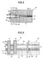
- each carbon fiber bundle 13 1 , 13 2 ??13 n extending from the multi-cable 10n is folded and inserted in the sheath 21 , as shown in Fig. 8 .
- the carbon fiber bundles 13 1 , 13 2 ??13 n are bridged with a plurality of U-shaped carbon fiber anchors 33 1 , 33 2 ??33 n , and tentative anchors 40 1 , 40 2 ??40 n are attached to the carbon fiber bundles 13 1 , 13 2 ??13 n .
- the sheath 21 in which the folded parts of th carbon fiber bundles 13 1 , 13 2 Vietnamese13 n are inserted, is located at one side of a molding box.
- the multi-cable 10n is straightened by stretching each cable of the multi-cable 10n .
- the straight carbon fiber cable 10 After the straight carbon fiber cable 10 , to which the U-shaped carbon fiber anchor 33 is fixed, or wherein the stretching carbon fiber cables 36 1r , 36 1l , 36 2r , 36 2l are bonded to the U-shaped carbon fiber anchors 35 r , 35 l formed at end parts of the straight carbon fiber cable 10 (Fig. 6) , is inserted in the sheath 21 , the straight carbon fiber cable 10 is set in a molding box. Green concrete is poured in the molding box under the condition that the straight carbon fiber cable 10 is stretched by pulling the tentative anchors 40a, 40b .
- a hydraulic jack is detached from the molding box without relaxation of the straight carbon fiber cable 10 .
- Grout 22 is then poured and hardened in the sheath 21 .
- a tacking tool is unloosed, each carbon fiber bundle 13a, 13b is cut off at a position between the tentative anchor 40a, 40b and a concrete body 23 .
- the pre-stressed concrete member 20 is taken out of the molding box and offered for a practical use.
- a compression force (i.e. pre-stress), which originates in shrinkage of the straight carbon fiber cable 10 released from a tension, is applied to the pre-stressed concrete member 20 fabricated in this way, since an anchoring effect is realized by the buried carbon fiber anchor 33 and the grout 22 in the sheath 21 .
- a pre-tension process uses a pre-tension apparatus 50 having anchor-fixing discs 51 , to which tentative anchors 40 1 , 40 2 .... 40 n can be attached with predetermined positional relationship, at both sides, as shown in Fig. 9 .
- a hydraulic jack 53 is located between each anchor-fixing disc 51 and a bearing wall 52 .
- Reinforcing members 32 , U-shaped carbon fiber anchors 33 and so on are bonded to a straight carbon fiber cable 10 by the same way as the post-tension process, except use of main reinforcing members 15 1 , 15 2 .... 15 n made of the straight carbon fiber cable 10 and a hoop 16 made of the straight carbon fiber bundle.
- a carbon fiber cable in which a cold-setting low-viscosity resin bond is preparatively infiltrated and cured, may be used as the straight carbon fiber cable 10 for the main reinforcing members 15 1 , 15 2 .... 15 n and the hoop 16 .
- Each tentative anchor 40 1 , 40 2 .... 40 n is bonded to a corresponding carbon fiber bundle 13 1 , 13 2 .... 13 n , and attached to a predetermined hole of the anchor-fixing disc 51 .
- each main reinforcing member 15 1 , 15 2 .... 15 n is held parallel to the other, when its both ends are inserted in the holes of the anchor-fixing discs 51 .
- the hoop 16 is wound around the main reinforcing members 15 1 , 15 2 .... 15 n , which are held with such positional relationship to define a predetermined sectional profile.
- the hoop 16 is bonded to the main reinforcing members 15 1 , 15 2 .... 15 n at crossing points with a resin bond.
- the main reinforcing members 15 1 , 15 2 .... 15 n integrated with the hoop 16 are expanded between the anchor-fixing discs 51, 51 , and the tentative anchors 40 1 , 40 2 .... 40 n are clamped to the anchor-fixing discs 51, 51 .
- the left-handed anchor-fixing disc 51 is shifted leftwards in Fig. 9 by actuation of the hydraulic jack 53 so as to stretch the main reinforcing members 15 1 , 15 2 .... 15 n .
- the main reinforcing members 15 1 , 15 2 .... 15 n Under the condition that the main reinforcing members 15 1 , 15 2 ....
- the pre-stressed concrete member 20 fabricated in this way is strengthened due to a compression force (i.e. pre-stress) originated in shrinkage of the main reinforcing members 15 1 , 15 2 .... 15 n released from the tension.
- a straight carbon fiber cable is impregnated with a cold-setting low-viscosity resin bond, stretched and molded as such in a concrete body.
- Arrangement of reinforcing members is fairly simplified in comparison with a conventional process using a composite member pre-cured with a thermosetting resin, and burial anchors are bonded to the straight carbon fiber cable at proper positions with ease. Since the straight carbon fiber cable is straightened by application of a tension and molded in concrete, the pre-stressed concrete member is improved in tensile strength, fatigue properties and crack-resistance.
- pre-stressed concrete member exhibits excellent corrosion-resistance even in a salty atmosphere.
- the pre-stressed concrete member is also handled with safe, since any part is not projected from its surface.
Landscapes
- Engineering & Computer Science (AREA)
- Architecture (AREA)
- Civil Engineering (AREA)
- Structural Engineering (AREA)
- Manufacturing & Machinery (AREA)
- Chemical & Material Sciences (AREA)
- Ceramic Engineering (AREA)
- Mechanical Engineering (AREA)
- Ropes Or Cables (AREA)
- Reinforcement Elements For Buildings (AREA)
- Manufacturing Of Tubular Articles Or Embedded Moulded Articles (AREA)
Applications Claiming Priority (3)
| Application Number | Priority Date | Filing Date | Title |
|---|---|---|---|
| JP2001155673 | 2001-05-24 | ||
| JP2001155673 | 2001-05-24 | ||
| PCT/JP2002/004777 WO2002094525A1 (en) | 2001-05-24 | 2002-05-17 | Method of manufacturing prestressed concrete |
Publications (2)
| Publication Number | Publication Date |
|---|---|
| EP1396321A1 true EP1396321A1 (de) | 2004-03-10 |
| EP1396321A4 EP1396321A4 (de) | 2006-04-05 |
Family
ID=18999812
Family Applications (1)
| Application Number | Title | Priority Date | Filing Date |
|---|---|---|---|
| EP02728074A Withdrawn EP1396321A4 (de) | 2001-05-24 | 2002-05-17 | Verfahren zur herstellung von spannbeton |
Country Status (5)
| Country | Link |
|---|---|
| US (1) | US7056463B2 (de) |
| EP (1) | EP1396321A4 (de) |
| JP (1) | JPWO2002094525A1 (de) |
| CA (1) | CA2446711C (de) |
| WO (1) | WO2002094525A1 (de) |
Cited By (4)
| Publication number | Priority date | Publication date | Assignee | Title |
|---|---|---|---|---|
| DE102007010574A1 (de) * | 2007-02-26 | 2008-08-28 | Deutsche Kahneisen Gesellschaft Mbh | Verwendung von Faserbüscheln als Verankerungselement im Betonbau |
| NO326727B1 (no) * | 2005-11-04 | 2009-02-02 | Bba Blackbull As | Armert betonglegeme og en fremgangsmåte for støping av et armert betonglegeme, samt et system for armering av et betonglegeme og en fremgangsmåte for fremstilling av et armeringsnett. |
| WO2016110293A3 (de) * | 2015-01-09 | 2016-11-24 | Technische Universität Dresden | Monolithisches betonprofil und herstellungsverfahren mittels gleitschalung sowie reparaturverfahren |
| DE102016211176A1 (de) * | 2016-06-22 | 2017-12-28 | Lenz Tankred | Verfahren und Vorrichtung zur Herstellung von Betonbauteilen |
Families Citing this family (23)
| Publication number | Priority date | Publication date | Assignee | Title |
|---|---|---|---|---|
| EP1694926A1 (de) * | 2003-12-10 | 2006-08-30 | The University Of Southern Queensland | Tragelement |
| FR2918689B1 (fr) * | 2007-07-09 | 2012-06-01 | Freyssinet | Procede de renforcement d'un ouvrage de construction, et ouvrage ainsi renforce. |
| US8511013B2 (en) | 2009-09-03 | 2013-08-20 | General Electric Company | Wind turbine tower and system and method for fabricating the same |
| CA2785362C (en) * | 2009-12-23 | 2018-04-17 | Geotech Pty Ltd | An anchorage system |
| EP2439359A1 (de) * | 2010-10-06 | 2012-04-11 | F.J. Aschwanden AG | Verfahren zum Verstärken von betonierten Platten im Bereich von Stützelementen |
| US20120298248A1 (en) * | 2011-05-26 | 2012-11-29 | Guido Schwager | Tendon duct, duct connector and duct termination therefor |
| RU2481946C2 (ru) * | 2011-08-18 | 2013-05-20 | Христофор Авдеевич Джантимиров | Способ изготовления комбинированно армированных бетонных изделий |
| US8919057B1 (en) | 2012-05-28 | 2014-12-30 | Tracbeam, Llc | Stay-in-place insulated concrete forming system |
| GB2507089A (en) * | 2012-10-18 | 2014-04-23 | Ccl Group Ltd | An anchor having expanded sections in multi wired tendons |
| US9341553B2 (en) | 2014-05-12 | 2016-05-17 | King Saud University | Apparatus for assessing durability of stressed fiber reinforced polymer (FRP) bars |
| DE202015002866U1 (de) * | 2015-04-17 | 2015-06-19 | Kolja Kuse | Solarmodul mit Steinrahmen |
| RU175371U1 (ru) * | 2017-06-15 | 2017-12-01 | Федеральное государственное бюджетное образовательное учреждение высшего образования "Поволжский государственный технологический университет" | Фундаментная плита с комбинированным армированием |
| JP6442104B1 (ja) * | 2017-07-31 | 2018-12-19 | 東京製綱株式会社 | 連続繊維補強より線の定着具 |
| US11242690B2 (en) * | 2018-01-19 | 2022-02-08 | Titcomb Brothers Manufacturing, Inc. | Loop tie for concrete forming panel systems |
| US10907365B2 (en) * | 2018-01-19 | 2021-02-02 | Titcomb Brothers Manufacturing, Inc. | Loop tie for concrete forming panel systems |
| JP7285043B2 (ja) * | 2018-01-25 | 2023-06-01 | 中日本高速道路株式会社 | プレキャストコンクリート版の接合構造 |
| CN108955949B (zh) * | 2018-07-02 | 2020-08-21 | 雷元新 | 一种大体积混凝土施工温度远程监控方法及装置 |
| JP7141953B2 (ja) * | 2019-01-15 | 2022-09-26 | 鹿島建設株式会社 | コンクリート用補強部材の接合構造、コンクリート用補強部材の定着部構造及びコンクリート用補強部材の接合方法 |
| JP7218187B2 (ja) * | 2019-01-22 | 2023-02-06 | 戸田建設株式会社 | 筋状繊維強化補強材を備えた構造物及びその製造方法 |
| CN110306728B (zh) * | 2019-06-13 | 2021-08-06 | 东南大学 | 一种frp筋锚固用扩大端头、加工方法及锚固方法 |
| JP2022064034A (ja) * | 2020-10-13 | 2022-04-25 | 東京製綱株式会社 | 緊張材の定着構造およびプレストレストコンクリート構造物の製作方法 |
| US12497793B2 (en) * | 2020-10-21 | 2025-12-16 | Kulstoff Composite Products, LLC | Fiber-reinforced polymer anchors and connectors for repair and strengthening of structures configured for field testing, and assemblies for field testing the same |
| US20240093494A1 (en) * | 2020-12-16 | 2024-03-21 | Sumitomo Mitsui Construction Co., Ltd. | Anchoring device and prestressed concrete |
Family Cites Families (35)
| Publication number | Priority date | Publication date | Assignee | Title |
|---|---|---|---|---|
| US2406270A (en) * | 1944-08-17 | 1946-08-20 | Bethlehem Steel Corp | Vibration dampening splice |
| US3115727A (en) * | 1957-11-29 | 1963-12-31 | Prescon Corp | Anchors for stranded pretensioned members |
| US3111569A (en) * | 1958-06-20 | 1963-11-19 | Rubenstein David | Packaged laminated constructions |
| US3086273A (en) * | 1959-12-28 | 1963-04-23 | Super Concrete Emulsions Ltd | Method for pre-stressing concrete |
| US3190065A (en) * | 1961-03-02 | 1965-06-22 | Fanner Mfg Co | Dead ends for cables |
| US3290840A (en) * | 1962-07-20 | 1966-12-13 | Prescon Corp | Method and means for chemically prestressing concrete |
| US3347005A (en) * | 1965-02-09 | 1967-10-17 | Cf & I Steel Corp | Prestressed concrete members |
| US3422586A (en) * | 1966-05-12 | 1969-01-21 | Domenico Parma | System for post-stressing concrete slabs,beams or other structures |
| US3399437A (en) * | 1967-04-11 | 1968-09-03 | William F. Kelly | Apparatus for post-tensioning prestressed concrete |
| US3513609A (en) * | 1968-03-13 | 1970-05-26 | Du Pont | Tendons for post-tensioned concrete construction |
| US3858991A (en) * | 1970-05-18 | 1975-01-07 | Reliable Electric Co | Apparatus for preassembling a cable and dead anchor |
| FR2122936A5 (de) * | 1971-01-21 | 1972-09-01 | Shakespeare Co | |
| BE794374A (fr) * | 1972-02-03 | 1973-07-23 | Trefilunion | Machine et procede de fabrication d'un treillis cylindrique expansible notament pour la realisation d'une armature de tuyau a emboitement, et treillis obtenu |
| US4121325A (en) * | 1976-12-06 | 1978-10-24 | Triple Bee Prestress (Proprietary) Limited | Cable anchoring and coupling equipment |
| CH614487A5 (de) * | 1977-02-27 | 1979-11-30 | Roland Frehner | |
| DE3207957C2 (de) * | 1982-03-05 | 1986-01-16 | Dyckerhoff & Widmann AG, 8000 München | Verfahren zum Erzeugen einer Ausbauchung an einer Litze aus Stahldrähten zu ihrer Verankerung in Bauteilen aus Beton sowie Vorrichtung zur Durchführung dieses Verfahrens |
| US4574545A (en) * | 1984-03-30 | 1986-03-11 | Breivik-Reigstad, Inc. | Method for installing or replacing tendons in prestressed concrete slabs |
| US4866903A (en) * | 1987-01-06 | 1989-09-19 | Ferstay William G | Positioning device |
| AU587442B2 (en) * | 1985-04-08 | 1989-08-17 | Sumitomo Electric Industries, Ltd. | Prestressing steel material |
| US4726163A (en) * | 1985-06-10 | 1988-02-23 | Jacobs William A | Prestressed plastic bodies and method of making same |
| GB2245287B (en) * | 1990-05-31 | 1994-03-02 | Robin Webb Consulting Limited | Tethers |
| JP2933102B2 (ja) * | 1991-04-09 | 1999-08-09 | 株式会社竹中工務店 | 繊維補強材とその製造方法および同補強材を用いた構造用材料 |
| JPH04366258A (ja) * | 1991-06-14 | 1992-12-18 | Mitsui Constr Co Ltd | 可撓性構造用材料 |
| JP2674903B2 (ja) * | 1991-06-28 | 1997-11-12 | 三井鉱山 株式会社 | 炭素繊維強化セメント系材料の製造方法 |
| JPH05269726A (ja) * | 1992-03-25 | 1993-10-19 | Mitsui Constr Co Ltd | 土木建築構造物補強材 |
| US5423362A (en) * | 1993-10-12 | 1995-06-13 | Knight; David W. | Apparatus for forming an access pocket at the terminal end of a post-tensioned tendon |
| US5540030A (en) * | 1994-07-01 | 1996-07-30 | Morrow; Jack A. | Process for the grouting of unbonded post-tensioned cables |
| ES2189862T3 (es) * | 1995-03-17 | 2003-07-16 | Empa | Elemento de traccion de varias capas en forma de lazo. |
| JPH09177246A (ja) * | 1995-12-27 | 1997-07-08 | Yoshiyuki Ogushi | 構造物の補強材 |
| US6082063A (en) * | 1996-11-21 | 2000-07-04 | University Technologies International Inc. | Prestressing anchorage system for fiber reinforced plastic tendons |
| US5939003A (en) * | 1997-01-31 | 1999-08-17 | Vsl International | Post-tensioning apparatus and method |
| JPH11124957A (ja) * | 1997-10-20 | 1999-05-11 | Tonen Corp | 強化繊維補強筋及びコンクリート構造物の補強方法 |
| JPH11350736A (ja) * | 1998-06-10 | 1999-12-21 | Nishimatsu Constr Co Ltd | ポストテンション工法における緊張材の定着方法、ポストテンション工法に用いる緊張材定着具、および緊張材定着具用スペーサー |
| JP3272320B2 (ja) * | 1999-02-03 | 2002-04-08 | 住友建設株式会社 | 緊張定着構造及び緊張定着方法 |
| JP3472746B2 (ja) * | 2000-04-28 | 2003-12-02 | 黒沢建設株式会社 | 緊張材ケーブル |
-
2002
- 2002-05-17 CA CA002446711A patent/CA2446711C/en not_active Expired - Fee Related
- 2002-05-17 US US10/478,362 patent/US7056463B2/en not_active Expired - Fee Related
- 2002-05-17 WO PCT/JP2002/004777 patent/WO2002094525A1/ja not_active Ceased
- 2002-05-17 EP EP02728074A patent/EP1396321A4/de not_active Withdrawn
- 2002-05-17 JP JP2002591223A patent/JPWO2002094525A1/ja active Pending
Cited By (8)
| Publication number | Priority date | Publication date | Assignee | Title |
|---|---|---|---|---|
| NO326727B1 (no) * | 2005-11-04 | 2009-02-02 | Bba Blackbull As | Armert betonglegeme og en fremgangsmåte for støping av et armert betonglegeme, samt et system for armering av et betonglegeme og en fremgangsmåte for fremstilling av et armeringsnett. |
| EP1945878A4 (de) * | 2005-11-04 | 2014-09-10 | Reforcetech As | Bewehrung für betonelemente und system und verfahren zur herstellung von stahlbetonelementen |
| DE102007010574A1 (de) * | 2007-02-26 | 2008-08-28 | Deutsche Kahneisen Gesellschaft Mbh | Verwendung von Faserbüscheln als Verankerungselement im Betonbau |
| WO2016110293A3 (de) * | 2015-01-09 | 2016-11-24 | Technische Universität Dresden | Monolithisches betonprofil und herstellungsverfahren mittels gleitschalung sowie reparaturverfahren |
| AT520899A5 (de) * | 2015-01-09 | 2019-08-15 | Univ Dresden Tech | Monolithisches Betonprofil und Herstellungsverfahren mittels Gleitschalung |
| DE102016211176A1 (de) * | 2016-06-22 | 2017-12-28 | Lenz Tankred | Verfahren und Vorrichtung zur Herstellung von Betonbauteilen |
| DE102016211176B4 (de) | 2016-06-22 | 2019-12-24 | Lenz Tankred | Verfahren und Verwendung einer Vorrichtung zur Durchführung des Verfahrens zur Herstellung von Betonbauteilen |
| US11407144B2 (en) | 2016-06-22 | 2022-08-09 | Tankred LENZ | Method and device for producing concrete components |
Also Published As
| Publication number | Publication date |
|---|---|
| WO2002094525A1 (en) | 2002-11-28 |
| EP1396321A4 (de) | 2006-04-05 |
| CA2446711C (en) | 2006-07-11 |
| US20040130063A1 (en) | 2004-07-08 |
| US7056463B2 (en) | 2006-06-06 |
| CA2446711A1 (en) | 2002-11-28 |
| JPWO2002094525A1 (ja) | 2004-09-02 |
Similar Documents
| Publication | Publication Date | Title |
|---|---|---|
| CA2446711C (en) | A process for manufacturing pre-stressed concrete members | |
| KR101576501B1 (ko) | Psc 빔의 시공방법 | |
| JP6442104B1 (ja) | 連続繊維補強より線の定着具 | |
| CN101680226A (zh) | 纤维增强筋 | |
| JP2018109268A (ja) | コンクリート構造物の補強方法、コンクリート構造物及び可撓性連続繊維補強材 | |
| KR101260537B1 (ko) | 금속 관구조와 이를 이용한 구조물을 보강하기 위한 방법 | |
| EP4553250A2 (de) | Verbindungselement, verfahren zur herstellung eines verbindungselements und zugehöriges installationskit | |
| US11566605B2 (en) | Method for manufacturing segments for a tower, prestressed segment, tower ring, tower, wind turbine, and prestressing device | |
| JPH02266065A (ja) | 炭素繊維強化プラスチック材の引張力の導入方法 | |
| EP4077830B1 (de) | Verbindungselement für die bauindustrie, verfahren zur konsolidierung eines struktur- und nichtstrukturelements und dazugehöriges installationskit | |
| JPH0742310A (ja) | コンクリ−ト補強用繊維複合型補強材およびその端末定着方法 | |
| JP2590930Y2 (ja) | グランドアンカ−用アンカー体 | |
| KR101628632B1 (ko) | 강연선의 고정정착 방법 | |
| CN109555111B (zh) | 一种低净空下的复合地连墙结构及施工方法 | |
| CN111350370A (zh) | 基于闭合截面预应力frp的钢柱加固修复结构及方法 | |
| JP2632488B2 (ja) | 高強力繊維撚合型frp緊張材の端末定着方法 | |
| JP7026601B2 (ja) | プレストレスト・コンクリート桁およびプレストレス導入方法 | |
| JP2001020461A (ja) | コンクリート部材用の補強材および補強構造 | |
| JP2020117979A (ja) | 解撚定着具を備えるプレストレストコンクリート床版及びプレストレス導入方法 | |
| JPH11302978A (ja) | 補強用緊張ロープの製造方法 | |
| JPH0413140B2 (de) | ||
| CN113802770A (zh) | 一种带有握裹力增强结包裹的线性构件加工铺设工艺 | |
| JP3669938B2 (ja) | 熱可塑性樹脂被覆frp製幅止め材の製造方法 | |
| JPH04363454A (ja) | プレストレスコンクリート | |
| JPH0953325A (ja) | 繊維複合線状材の緊張・定着方法とその定着部構造 |
Legal Events
| Date | Code | Title | Description |
|---|---|---|---|
| PUAI | Public reference made under article 153(3) epc to a published international application that has entered the european phase |
Free format text: ORIGINAL CODE: 0009012 |
|
| 17P | Request for examination filed |
Effective date: 20031106 |
|
| AK | Designated contracting states |
Kind code of ref document: A1 Designated state(s): AT BE CH CY DE DK ES FI FR GB GR IE IT LI LU MC NL PT SE TR |
|
| RAP1 | Party data changed (applicant data changed or rights of an application transferred) |
Owner name: JAPAN SCIENCE AND TECHNOLOGY AGENCY |
|
| A4 | Supplementary search report drawn up and despatched |
Effective date: 20060217 |
|
| RIC1 | Information provided on ipc code assigned before grant |
Ipc: E04C 5/07 20060101ALI20060213BHEP Ipc: B28B 23/04 20060101AFI20021204BHEP Ipc: E04C 5/12 20060101ALI20060213BHEP |
|
| 17Q | First examination report despatched |
Effective date: 20070621 |
|
| RAP1 | Party data changed (applicant data changed or rights of an application transferred) |
Owner name: FRONTIER TECHNOLOGICAL RESEARCH LABORATORY CO., LT |
|
| GRAP | Despatch of communication of intention to grant a patent |
Free format text: ORIGINAL CODE: EPIDOSNIGR1 |
|
| STAA | Information on the status of an ep patent application or granted ep patent |
Free format text: STATUS: THE APPLICATION IS DEEMED TO BE WITHDRAWN |
|
| 18D | Application deemed to be withdrawn |
Effective date: 20091014 |