EP1396409A1 - Ensemble de ferroutage et son procédé de manutention - Google Patents
Ensemble de ferroutage et son procédé de manutention Download PDFInfo
- Publication number
- EP1396409A1 EP1396409A1 EP03356130A EP03356130A EP1396409A1 EP 1396409 A1 EP1396409 A1 EP 1396409A1 EP 03356130 A EP03356130 A EP 03356130A EP 03356130 A EP03356130 A EP 03356130A EP 1396409 A1 EP1396409 A1 EP 1396409A1
- Authority
- EP
- European Patent Office
- Prior art keywords
- transfer
- receiving member
- vehicle
- assembly according
- piggyback
- Prior art date
- Legal status (The legal status is an assumption and is not a legal conclusion. Google has not performed a legal analysis and makes no representation as to the accuracy of the status listed.)
- Granted
Links
- 238000000034 method Methods 0.000 title claims description 6
- 238000006073 displacement reaction Methods 0.000 claims description 5
- 230000000087 stabilizing effect Effects 0.000 claims description 4
- 210000000056 organ Anatomy 0.000 claims description 2
- 241001071864 Lethrinus laticaudis Species 0.000 claims 2
- 230000000284 resting effect Effects 0.000 claims 1
- 239000003381 stabilizer Substances 0.000 claims 1
- 230000032258 transport Effects 0.000 description 11
- 210000003323 beak Anatomy 0.000 description 5
- 230000006641 stabilisation Effects 0.000 description 5
- 239000000523 sample Substances 0.000 description 2
- 238000011105 stabilization Methods 0.000 description 2
- 208000031968 Cadaver Diseases 0.000 description 1
- 239000010426 asphalt Substances 0.000 description 1
- 238000012550 audit Methods 0.000 description 1
- 238000010276 construction Methods 0.000 description 1
- 230000005611 electricity Effects 0.000 description 1
- 230000005484 gravity Effects 0.000 description 1
- 238000009434 installation Methods 0.000 description 1
- 210000001331 nose Anatomy 0.000 description 1
- 235000020004 porter Nutrition 0.000 description 1
- 238000005096 rolling process Methods 0.000 description 1
- 102000012498 secondary active transmembrane transporter activity proteins Human genes 0.000 description 1
- 108040003878 secondary active transmembrane transporter activity proteins Proteins 0.000 description 1
- 238000005728 strengthening Methods 0.000 description 1
- 238000003466 welding Methods 0.000 description 1
Images




Classifications
-
- B—PERFORMING OPERATIONS; TRANSPORTING
- B61—RAILWAYS
- B61D—BODY DETAILS OR KINDS OF RAILWAY VEHICLES
- B61D3/00—Wagons or vans
- B61D3/16—Wagons or vans adapted for carrying special loads
- B61D3/18—Wagons or vans adapted for carrying special loads for vehicles
- B61D3/182—Wagons or vans adapted for carrying special loads for vehicles specially adapted for heavy vehicles, e.g. public work vehicles, trucks, trailers
- B61D3/184—Wagons or vans adapted for carrying special loads for vehicles specially adapted for heavy vehicles, e.g. public work vehicles, trucks, trailers the heavy vehicles being of the trailer or semi-trailer type
-
- B—PERFORMING OPERATIONS; TRANSPORTING
- B61—RAILWAYS
- B61D—BODY DETAILS OR KINDS OF RAILWAY VEHICLES
- B61D47/00—Loading or unloading devices combined with vehicles, e.g. loading platforms, doors convertible into loading and unloading ramps
- B61D47/005—Loading or unloading devices combined with road vehicles carrying wagons, e.g. ramps, turntables, lifting means
Definitions
- the present invention relates to a set of piggyback, as well as its handling process.
- piggybacking Such combined transport, of character at a time road and rail is referred to as piggybacking.
- the invention proposes to carry out a piggyback set using hardware railway equipped with standard wheels, whose diameter is for example equal to 920 mm or even 840 mm strictly.
- the invention also aims at using fixed terminal installations as simple as possible, in particular that can be reduced to a railway embedded in road asphalt, of limited width for example a dozen meters on either side of the way. In this context, it is also desirable that the potential catenary remains energized for the duration the transfer of the road vehicle.
- the invention also aims to avoid the use, in terminal stations, lifting equipment that is too large, which therefore have a high cost, such as gantry cranes, or sophisticated forklifts.
- the invention further proposes to provide a railway vehicle belonging to the whole of aforementioned piggyback, which is mainly built at from classical elements.
- a further object of the invention is to conceive adjusting members, allowing the device to be adapted the road vehicle, according to any rail gauge constraints.
- the invention aims to propose a set of piggyback, which is able to load all vehicles according to the European directives in force.
- a piggyback assembly comprising a rail transport vehicle, a reception member of a road vehicle, and at least two transfer devices, adapted to cooperate with this receiving member, characterized in that the railway vehicle defines a median housing volume of a body of the receiving member, this housing volume being open laterally on a free open side of the railway vehicle, said rail vehicle being further provided with means for supporting the body of the the receiving member, in a position of attachment of the latter, each transfer device being provided with a movable transfer member between a folded position and an extended position, the receiving member being dug means allowing the passage of each transfer member, in said securing position, while there is provided means for moving this receiving member, able to move it between said securing position and a raised position relative to the rail vehicle, for the purpose of transfer of this receiving member.
- the set of piggyback of the invention firstly comprises a wagon railway, referred to as a whole by reference 2.
- This carrier wagon comprises a bogie before 4, and a rear bogie 6, intended to rest on rails R.
- Each boggie supports an end platform, respectively 8 and back 10.
- Two beaches 20 and 22 extend from the end lower of a corresponding apron 16 or 18.
- the facing aprons 16 and 18 are connected by two smooth 34 and 36, extending one below the other, level of the first side of the wagon 2.
- the two facing ranges 20 and 22 are mutually connected by a pulling down 38, extending along the main axis A of the wagon 2.
- the rails 34 and 36, as well as the tie rod 38 may allow the passage of different lines, especially compressed air and electricity, necessary for the proper functioning of the convoy rail.
- the railway wagon is built so as to respect, particularly in the lower part, the common railway gauges.
- each platform in this case 8, and the beach adjacent to it, in this case 20, may be reinforced by a square 40.
- the middle part of the carrier wagon 2 located between platforms 8 and 10 is formed only of the rails 34 and 36, as well as the low tug 38. This thus contributes to create, in this middle part, a free volume V, open laterally on the side 2 'opposite the rails 34 and 36.
- the piggyback assembly according to the invention comprises also a drawer 102, forming a receiving device at least one road vehicle, such as a heavy vehicle, which is not shown in the figures.
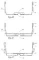
- This drawer has a body 104, having a shape of U, in cross section.
- the latter is provided with a floor 106, whose upper face is reinforced with a longitudinal rib 108, as well as different transverse ribs. It can thus be expected a medial transverse rib 110, as well as two ribs transverse ends 112.
- the floor of the drawer will be arranged to receive wedges to immobilize the wheels of vehicles during rail transport.
- the floor 106 is extended by two side walls 116 and 118. It should be noted that one of these 116 walls, intended to be received on the open lateral side 2 ' of car 2, is completely smooth. On the other hand, the other wall 118 has, on its outer face, a recess median 120, as well as a lower shoulder 122.
- the rails 34 and 36 are represented in phantom, in the position of solidarity, by gravity, of the drawer 102 on the wagon 2. It can be noted that the height of the recess 120 is greater than that of the upper arm 34, which confers a possibility of vertical deflection, necessary both for unlocking the drawer, but also for its possible calibration for traffic on all networks below, whereas the low rail 36 rests against the lower face of the shoulder 122.
- the median volume V wagon thus allows the housing of the body 104 of the drawer.
- the thickness of the side walls 116 and 118 can possibly be increased towards the ends of the drawer 102. This allows a possible strengthening of the beaks described below, supporting the drawer and its load.
- small lifting ramps At the floor end of the drawer are provided small lifting ramps, the length of which is example of 45 centimeters, to facilitate the access of road vehicles inside the drawer despite the weak vertical drop (only twenty centimeters) between the above the end beam of the drawer floor and the ground of the road track.
- the side walls 116 and 118 are extended to both ends with side noses 124, provided thus four in number.
- These beaks which are intended for rest on platforms 8 and 10 of car 2, are dug unrepresented blind holes intended for receive the pins 26 and 28, which are provided with these platforms.
- Notches 126 intended as will be seen in following with the passage of slides, are in addition arranged in the underside of these beaks 124 (see especially Figure 2E).
- the piggyback assembly according to the invention comprises finally a device ensuring the transfer of the drawer 102.
- device called “ferry”, which is assigned in its reference 202, is more particularly visible in FIGS. 3A to 3F.
- This chassis 204 comprises a frame 204, mounted on wheels 206, which supports a driving cabin 208.
- the part superior of this chassis 204 constitutes a platform on which are mounted one or more slide (s) 210, which are equipped with rollers 212, in order to ensure easier movement.
- each slider 210 comprises a bottom 210 'and an upper part mobile 210 ", which can be moved away from the bottom by intermediate cylinders 214.
- This upper part is, in addition, provided with two pairs of shoulders 216, thus delimiting two dwellings 217 intended to receive the underside of spouts 124.
- a probe 214 of a type known in self, which allows to adjust the levels of the trays of the wagon and the transfer device, as will be described in what follows.
- Cylinders of which only one 216 is shown, ensure the setting in motion of the slides, according to an axis globally horizontal. Additional cylinders 218 also ensure the lifting of the entire transfer 202, for its upgrade with the tray of the corresponding wagon.
- the jacks 218 of the transfer device 202 are maneuvered so as to raise the latter, according to the arrow F 1 .
- the upper wall of the frame 204 is advantageously placed slightly above the platforms 8 and 10 of the wagon 2.
- This operation allows the establishment of the probe 214, which is operated horizontally according to the arrow F 2 . This then controls the exact leveling of the platform of the ferry 202 with the platform 8 of the carrier wagon 2.
- each slide 210 At the end of this movement, the two housings 217 of each slide 210 are at the right of a corresponding nozzle 124.
- the upper part of the slide 210 is then raised, for example about ten centimeters (arrow F 4 ), by the cylinders 214 incorporated in said slide, so as to obtain the unlocking of the pins 26, 28, 30 and 32 and 38.
- These beaks are then received in the housing 217 of the slide 210, as shown in Figure 3D.
- the drawer 102 now rests on the ground, in being disconnected from the transfer device 202. This The last can therefore withdraw, so as to win another workplace. Moreover, the road vehicle, initially received on the drawer 102, can be released, in order to move independently.
- ferries can be rather small size, because the handling of the receiving organ are always trans-ferries to stop and stalled by their cylinders.
- this drawer could be controlled by solidarity slides of the aprons 16 and 18 of the carrier wagon which would then be "Symmetrical", since provided with two smooth rails 36 and 38.
- Symmetrical since provided with two smooth rails 36 and 38.
Landscapes
- Engineering & Computer Science (AREA)
- Transportation (AREA)
- Mechanical Engineering (AREA)
- Loading Or Unloading Of Vehicles (AREA)
- Handcart (AREA)
- Machines For Laying And Maintaining Railways (AREA)
- Press Drives And Press Lines (AREA)
Abstract
Description
caractérisé en ce que
le véhicule ferroviaire définit un volume médian de logement d'un corps de l'organe de réception, ce volume de logement étant ouvert latéralement sur un côté ouvert libre du véhicule ferroviaire, ce véhicule ferroviaire étant en outre pourvu de moyens assurant support du corps de l'organe de réception, dans une position de solidarisation de ce dernier, chaque dispositif de transfert étant pourvu d'un organe de transfert mobile entre une position repliée et une position déployée, l'organe de réception étant creusé de moyens permettant le passage de chaque organe de transfert, dans ladite position de solidarisation, alors qu'il est prévu des moyens de déplacement de cet organe de réception, aptes à le déplacer entre ladite position de solidarisation et une position rehaussée par rapport à ce véhicule ferroviaire, en vue du transfert de cet organe de réception.
- les moyens de support de l'organe de réception comprennent au moins une lisse, prévue sur le côté du véhicule ferroviaire opposé audit côté ouvert libre, ainsi qu'au moins un tirant, s'étendant en partie basse du véhicule ferroviaire ;
- le corps de l'organe de réception possède une paroi latérale pourvue d'un renfoncement et/ou d'un épaulement, aptes à coopérer avec la ou chaque lisse ;
- l'organe de réception est pourvu, à ses deux extrémités longitudinales, de becs destinés à reposer sur des plate-formes placées aux extrémités du véhicule ferroviaire ;
- l'organe de transfert du dispositif de transfert est une glissière, qui est mobile horizontalement par rapport à un châssis de ce dispositif de transfert ;
- les moyens de passage de l'organe de transfert comprennent au moins une encoche ménagée dans l'organe de réception ;
- il est prévu plusieurs encoches, dont chacune est ménagée dans un bec correspondant de l'organe de réception ;
- les moyens de déplacement appartiennent au dispositif de transfert ;
- chaque glissière comprend un fond, ainsi qu'une partie supérieure, mobile par rapport à ce fond sous l'action des moyens de déplacement, qui sont notamment formés par au moins un vérin.
- on effectue au moins les étapes b) à d) en maintenant les dispositifs de transfert dans une configuration stabilisée, notamment par action de vérins de stabilisation ;
- on manoeuvre les vérins de stabilisation des dispositifs de transfert, ainsi que des vérins de stabilisation du véhicule ferroviaire de manière à créer une légère pente formée par les plate-formes quasiment accolées dudit véhicule et des dispositifs de transfert afin de faciliter la mise en oeuvre de l'étape d).
- les figures 1A, 1B et 1C sont des vues respectivement de dessus, de côté, ainsi qu'en coupe suivant la ligne I-I à la figure 1A, illustrant un wagon ferroviaire appartenant à l'ensemble de ferroutage de l'invention, dit « porteur » ;
- la figure 2A est une vue de dessus, illustrant un dispositif de réception d'un véhicule routier, appartenant également à l'ensemble de ferroutage de l'invention, dit « tiroir » ;
- les figures 2B, 2C et 2D sont des vues en coupe, selon les lignes II-II, III-III et IV-IV à la figure 2A ;
- la figure 2E est une vue de côté, à plus grande échelle, illustrant un bec du tiroir des figures 2A à 2D ;
- les figures 3A à 3F sont des vues de face illustrant différentes phases de la mise en oeuvre de l'ensemble de ferroutage de l'invention ; et
- la figure 4 est une vue de côté, illustrant une glissière d'un organe de transfert appartenant à l'ensemble conforme à l'invention.
Claims (12)
- Ensemble de ferroutage, comprenant un véhicule de transport ferroviaire (2), un organe de réception (102) d'un véhicule routier, ainsi qu'au moins deux dispositifs de transfert (202), aptes à coopérer avec cet organe de réception,
caractérisé en ce que
le véhicule ferroviaire (2) définit un volume médian (V) de logement d'un corps (104) de l'organe de réception (102), ce volume de logement étant ouvert latéralement sur un côté ouvert libre (2') du véhicule ferroviaire, ce véhicule ferroviaire étant en outre pourvu de moyens (34, 36, 38) assurant support du corps (104) de l'organe de réception, dans une position de solidarisation (figure 3A) de ce dernier, chaque dispositif de transfert (202) étant pourvu d'un organe de transfert (210) mobile entre une position repliée (figure 3B) et une position déployée (figures 3C et 3E), l'organe de réception étant creusé de moyens (126) permettant le passage de chaque organe de transfert (210), dans ladite position de solidarisation, alors qu'il est prévu des moyens de déplacement (214) de cet organe de réception, aptes à le déplacer entre ladite position de solidarisation et une position rehaussée (figure 3B) par rapport à ce véhicule ferroviaire, en vue du transfert de cet organe de réception. - Ensemble de ferroutage selon la revendication 1, caractérisé en ce que les moyens de support de l'organe de réception (102) comprennent au moins une lisse (34, 36), prévue sur le côté du véhicule ferroviaire opposé audit côté ouvert libre (2'), ainsi qu'au moins un tirant (38), s'étendant en partie basse du véhicule ferroviaire.
- Ensemble de ferroutage selon la revendication 2, caractérisé en ce que le corps (104) de l'organe de réception (102) possède une paroi latérale pourvue d'un renfoncement (120) et/ou d'un épaulement (122), aptes à coopérer avec la ou chaque lisse (34, 36).
- Ensemble de ferroutage selon l'une quelconque des revendications précédentes, caractérisé en ce que l'organe de réception (102) est pourvu, à ses deux extrémités longitudinales, de becs (124) destinés à reposer sur des plate-formes (8, 10) placées aux extrémités du véhicule ferroviaire (2).
- Ensemble de ferroutage selon l'une quelconque des revendications précédentes, caractérisé en ce que l'organe de transfert du dispositif de transfert (202) est une glissière (210), qui est mobile horizontalement par rapport à un châssis (204) de ce dispositif de transfert.
- Ensemble de ferroutage selon l'une quelconque des revendications précédentes, caractérisé en ce que les moyens de passage de l'organe de transfert (210) comprennent au moins une encoche (126) ménagée dans l'organe de réception (102).
- Ensemble de ferroutage selon les revendications 4 et 6, caractérisé en ce qu'il est prévu plusieurs encoches (126), dont chacune est ménagée dans un bec correspondant (124) de l'organe de réception.
- Ensemble de ferroutage selon l'une quelconque des revendications précédentes, caractérisé en ce que les moyens de déplacement (214) appartiennent au dispositif de transfert (202) .
- Ensemble de ferroutage selon les revendications 5 et 8, caractérisée en ce que chaque glissière comprend un fond (210'), ainsi qu'une partie supérieure (210''), mobile par rapport à ce fond sous l'action des moyens de déplacement, qui sont notamment formés par au moins un vérin (214) .
- Procédé de manutention de l'ensemble de ferroutage conforme à l'une quelconque des revendications précédentes, caractérisé en ce qu'il comprend les étapes suivantes :a) on approche deux dispositifs de transfert (202) des extrémités correspondantes de l'organe de réception (102), au niveau du côté ouvert libre (2') du véhicule ferroviaire (2), jusqu'à ce que ces dispositifs de transfert soient quasiment au contact dudit véhicule (2) ;b) on amène l'organe de transfert (210) dans sa position déployée (figure 3C), en l'engageant au travers des moyens de passage (126) de l'organe de réception (102) ;c) on manoeuvre les moyens de déplacement (214), de manière à amener l'organe de réception (102) dans sa position rehaussée ;d) on ramène l'organe de transfert dans sa position repliée (figure 3F) ;ete) on désolidarise (figure 3G) l'organe de réception (102) par rapport au dispositif de transfert (202) .
- Procédé selon la revendication 10, caractérisé en ce qu'on effectue au moins les étapes b) à d) en maintenant les dispositifs de transfert (202) dans une configuration stabilisée, notamment par action de vérins de stabilisation (218) .
- Procédé selon la revendication 11, caractérisé en ce qu'on manoeuvre les vérins (218) de stabilisation des dispositifs de transfert (202), ainsi que des vérins (42) de stabilisation du véhicule ferroviaire (2) de manière à créer une légère pente formée par les plate-formes quasiment accolées dudit véhicule (2) et des dispositifs de transfert (202) afin de faciliter la mise en oeuvre de l'étape d) .
Applications Claiming Priority (2)
| Application Number | Priority Date | Filing Date | Title |
|---|---|---|---|
| FR0210934A FR2843929B1 (fr) | 2002-09-04 | 2002-09-04 | Ensemble de ferroutage et son procede de manutention |
| FR0210934 | 2002-09-04 |
Publications (2)
| Publication Number | Publication Date |
|---|---|
| EP1396409A1 true EP1396409A1 (fr) | 2004-03-10 |
| EP1396409B1 EP1396409B1 (fr) | 2008-05-28 |
Family
ID=31503100
Family Applications (1)
| Application Number | Title | Priority Date | Filing Date |
|---|---|---|---|
| EP03356130A Expired - Lifetime EP1396409B1 (fr) | 2002-09-04 | 2003-09-01 | Ensemble de ferroutage et son procédé de manutention |
Country Status (4)
| Country | Link |
|---|---|
| EP (1) | EP1396409B1 (fr) |
| AT (1) | ATE396897T1 (fr) |
| DE (1) | DE60321279D1 (fr) |
| FR (1) | FR2843929B1 (fr) |
Cited By (1)
| Publication number | Priority date | Publication date | Assignee | Title |
|---|---|---|---|---|
| ITNA20090070A1 (it) * | 2009-11-25 | 2011-05-25 | Iorio Antonio De | Carro polifunzionale canguro per trasporto merci su ferro. |
Families Citing this family (1)
| Publication number | Priority date | Publication date | Assignee | Title |
|---|---|---|---|---|
| FR2884479A1 (fr) * | 2005-04-14 | 2006-10-20 | Arbel Fauvet Rail Sa | Nacelle destinee a recevoir une semi-remorque, wagon equipe d'une nacelle et procede de chargement de la semi-remorque |
Citations (4)
| Publication number | Priority date | Publication date | Assignee | Title |
|---|---|---|---|---|
| US5988073A (en) * | 1995-05-26 | 1999-11-23 | Eriksson; Jan | Railway waggon |
| EP1010600A2 (fr) * | 1998-12-15 | 2000-06-21 | Firma Walter Back | Système de transbordement pour charger ou décharger des véhicules sur ou à partir de wagons ferroviaires |
| DE10003315A1 (de) * | 1999-06-25 | 2000-12-28 | Abb Patent Gmbh | Einrichtung und Verfahren zur Be- und Entladung von Schienenwaggons für den kombinierten Schienenverkehr |
| FR2810609A1 (fr) * | 2000-06-21 | 2001-12-28 | Lohr Ind | Wagon pour le transport combine rail/route comprenant deux plates-formes d'extremite supportant une structure ferroviaire pivotante porteuse de la charge routiere |
-
2002
- 2002-09-04 FR FR0210934A patent/FR2843929B1/fr not_active Expired - Fee Related
-
2003
- 2003-09-01 AT AT03356130T patent/ATE396897T1/de not_active IP Right Cessation
- 2003-09-01 EP EP03356130A patent/EP1396409B1/fr not_active Expired - Lifetime
- 2003-09-01 DE DE60321279T patent/DE60321279D1/de not_active Expired - Lifetime
Patent Citations (4)
| Publication number | Priority date | Publication date | Assignee | Title |
|---|---|---|---|---|
| US5988073A (en) * | 1995-05-26 | 1999-11-23 | Eriksson; Jan | Railway waggon |
| EP1010600A2 (fr) * | 1998-12-15 | 2000-06-21 | Firma Walter Back | Système de transbordement pour charger ou décharger des véhicules sur ou à partir de wagons ferroviaires |
| DE10003315A1 (de) * | 1999-06-25 | 2000-12-28 | Abb Patent Gmbh | Einrichtung und Verfahren zur Be- und Entladung von Schienenwaggons für den kombinierten Schienenverkehr |
| FR2810609A1 (fr) * | 2000-06-21 | 2001-12-28 | Lohr Ind | Wagon pour le transport combine rail/route comprenant deux plates-formes d'extremite supportant une structure ferroviaire pivotante porteuse de la charge routiere |
Cited By (1)
| Publication number | Priority date | Publication date | Assignee | Title |
|---|---|---|---|---|
| ITNA20090070A1 (it) * | 2009-11-25 | 2011-05-25 | Iorio Antonio De | Carro polifunzionale canguro per trasporto merci su ferro. |
Also Published As
| Publication number | Publication date |
|---|---|
| FR2843929A1 (fr) | 2004-03-05 |
| DE60321279D1 (de) | 2008-07-10 |
| ATE396897T1 (de) | 2008-06-15 |
| EP1396409B1 (fr) | 2008-05-28 |
| FR2843929B1 (fr) | 2004-10-22 |
Similar Documents
| Publication | Publication Date | Title |
|---|---|---|
| CA1249859A (fr) | Vehicule porte-voitures a structures porteuses transversales individuelles propres a chaque train de roues | |
| CA2659495C (fr) | Vehicule ferroviaire a plate-forme et marchepied mobiles | |
| EP1292476B1 (fr) | Systeme de transport et de chargement/dechargement des wagons en oblique dans une gare ferroviaire de transport combine rail/route et son procede de mise en oeuvre | |
| EP3174757B1 (fr) | Palette porteuse amovible, individuelle et universelle, pour véhicule porte-voitures | |
| EP1349763B1 (fr) | Unite ferroviaire a structure porteuse pivotante pour le transport combine rail/route soit d'une semi-remorque soit de deux vehicules a moteur | |
| EP3645365B1 (fr) | Procede de chargement/dechargement d'une semi-remorque routiere sur un wagon-poche et wagon-poche adapte a ce procede | |
| EP0564555A1 (fr) | Appareil permettant d'assurer le transbordement lateral des conteneurs. | |
| WO1993003945A1 (fr) | Unite dissociable de transport ferroviaire porteuse d'un chargement, notamment d'une unite routiere | |
| EP1396409B1 (fr) | Ensemble de ferroutage et son procédé de manutention | |
| EP0515294B1 (fr) | Liaison articulée dissociable du type à col de cygne entre un véhicule porteur-remorqueur et une semi-remorque porte-engins | |
| EP0905001A1 (fr) | Système pour le transport, chargement et déchargement sur wagons de véhicules routiers, containers ou autres marchandises et wagons adaptés | |
| EP2303632B1 (fr) | Dispositif de manutention-roulage pour conteneur ou analogue et procede pour deplacer deux tels dispositifs en l'absence de conteneur | |
| EP1874584A1 (fr) | Wagon pour le transport de vehicules routiers a plans porteurs mobiles entre une position de transport et une position de circulation inter-wagon et train constitue de tels wagons | |
| FR2612145A1 (fr) | Dispositif d'accrochage adaptable sur des boggies ferroviaires pour l'accouplement entre deux remorques de transport routier | |
| FR2985239A1 (fr) | Wagon de transport de vehicules, notamment pour un systeme de transport rail/route | |
| FR2940937A1 (fr) | Dispositif de support destine a faciliter le chargement d'un caisson ou d'un plateau sur une plate-forme | |
| FR2644118A1 (fr) | Conteneur pour le transport de produits en vrac | |
| EP1827903B1 (fr) | Remorque de transport susceptible d'etre charge et decharge au moyen d'un camion equipe d'un bras de prehension | |
| FR2473446A1 (fr) | Wagon demontable pour la coordination technique du transport rail-route | |
| FR3043394B1 (fr) | Systeme d'embarquement d'un chariot elevateur sous une plateforme de chargement d'un vehicule de transport | |
| FR3037308A1 (fr) | Remorque destinee a etre attelee a un vehicule tracteur et ensemble attele comprenant une telle remorque | |
| FR3052763A1 (fr) | Dispositif d'immobilisation d'une structure mobile a bequilles de reception de chargement et procede de mise en oeuvre | |
| FR2519600A1 (fr) | Perfectionnements aux semi-remorques porte-engin a plateau surbaisse | |
| FR2482031A2 (fr) | Wagon demontable pour la coordination technique du transport rail-route | |
| FR2458423A1 (fr) | Materiel de transport de conteneurs, notamment de conteneurs normalises |
Legal Events
| Date | Code | Title | Description |
|---|---|---|---|
| PUAI | Public reference made under article 153(3) epc to a published international application that has entered the european phase |
Free format text: ORIGINAL CODE: 0009012 |
|
| AK | Designated contracting states |
Kind code of ref document: A1 Designated state(s): AT BE BG CH CY CZ DE DK EE ES FI FR GB GR HU IE IT LI LU MC NL PT RO SE SI SK TR |
|
| AX | Request for extension of the european patent |
Extension state: AL LT LV MK |
|
| 17P | Request for examination filed |
Effective date: 20040522 |
|
| AKX | Designation fees paid |
Designated state(s): AT BE BG CH CY CZ DE DK EE ES FI FR GB GR HU IE IT LI LU MC NL PT RO SE SI SK TR |
|
| AXX | Extension fees paid |
Extension state: LT Payment date: 20040828 |
|
| GRAP | Despatch of communication of intention to grant a patent |
Free format text: ORIGINAL CODE: EPIDOSNIGR1 |
|
| GRAS | Grant fee paid |
Free format text: ORIGINAL CODE: EPIDOSNIGR3 |
|
| GRAA | (expected) grant |
Free format text: ORIGINAL CODE: 0009210 |
|
| AK | Designated contracting states |
Kind code of ref document: B1 Designated state(s): AT BE BG CH CY CZ DE DK EE ES FI FR GB GR HU IE IT LI LU MC NL PT RO SE SI SK TR |
|
| AX | Request for extension of the european patent |
Extension state: LT |
|
| REG | Reference to a national code |
Ref country code: GB Ref legal event code: FG4D Free format text: NOT ENGLISH |
|
| REG | Reference to a national code |
Ref country code: CH Ref legal event code: EP |
|
| REF | Corresponds to: |
Ref document number: 60321279 Country of ref document: DE Date of ref document: 20080710 Kind code of ref document: P |
|
| REG | Reference to a national code |
Ref country code: IE Ref legal event code: FG4D Free format text: LANGUAGE OF EP DOCUMENT: FRENCH |
|
| REG | Reference to a national code |
Ref country code: RO Ref legal event code: EPE |
|
| PG25 | Lapsed in a contracting state [announced via postgrant information from national office to epo] |
Ref country code: SI Free format text: LAPSE BECAUSE OF FAILURE TO SUBMIT A TRANSLATION OF THE DESCRIPTION OR TO PAY THE FEE WITHIN THE PRESCRIBED TIME-LIMIT Effective date: 20080528 |
|
| PG25 | Lapsed in a contracting state [announced via postgrant information from national office to epo] |
Ref country code: FI Free format text: LAPSE BECAUSE OF FAILURE TO SUBMIT A TRANSLATION OF THE DESCRIPTION OR TO PAY THE FEE WITHIN THE PRESCRIBED TIME-LIMIT Effective date: 20080528 Ref country code: ES Free format text: LAPSE BECAUSE OF FAILURE TO SUBMIT A TRANSLATION OF THE DESCRIPTION OR TO PAY THE FEE WITHIN THE PRESCRIBED TIME-LIMIT Effective date: 20080908 |
|
| PG25 | Lapsed in a contracting state [announced via postgrant information from national office to epo] |
Ref country code: AT Free format text: LAPSE BECAUSE OF FAILURE TO SUBMIT A TRANSLATION OF THE DESCRIPTION OR TO PAY THE FEE WITHIN THE PRESCRIBED TIME-LIMIT Effective date: 20080528 Ref country code: NL Free format text: LAPSE BECAUSE OF FAILURE TO SUBMIT A TRANSLATION OF THE DESCRIPTION OR TO PAY THE FEE WITHIN THE PRESCRIBED TIME-LIMIT Effective date: 20080528 |
|
| NLV1 | Nl: lapsed or annulled due to failure to fulfill the requirements of art. 29p and 29m of the patents act | ||
| REG | Reference to a national code |
Ref country code: IE Ref legal event code: FD4D |
|
| PG25 | Lapsed in a contracting state [announced via postgrant information from national office to epo] |
Ref country code: SE Free format text: LAPSE BECAUSE OF FAILURE TO SUBMIT A TRANSLATION OF THE DESCRIPTION OR TO PAY THE FEE WITHIN THE PRESCRIBED TIME-LIMIT Effective date: 20080828 Ref country code: IE Free format text: LAPSE BECAUSE OF FAILURE TO SUBMIT A TRANSLATION OF THE DESCRIPTION OR TO PAY THE FEE WITHIN THE PRESCRIBED TIME-LIMIT Effective date: 20080528 Ref country code: DK Free format text: LAPSE BECAUSE OF FAILURE TO SUBMIT A TRANSLATION OF THE DESCRIPTION OR TO PAY THE FEE WITHIN THE PRESCRIBED TIME-LIMIT Effective date: 20080528 Ref country code: CZ Free format text: LAPSE BECAUSE OF FAILURE TO SUBMIT A TRANSLATION OF THE DESCRIPTION OR TO PAY THE FEE WITHIN THE PRESCRIBED TIME-LIMIT Effective date: 20080528 Ref country code: PT Free format text: LAPSE BECAUSE OF FAILURE TO SUBMIT A TRANSLATION OF THE DESCRIPTION OR TO PAY THE FEE WITHIN THE PRESCRIBED TIME-LIMIT Effective date: 20081028 |
|
| PG25 | Lapsed in a contracting state [announced via postgrant information from national office to epo] |
Ref country code: SK Free format text: LAPSE BECAUSE OF FAILURE TO SUBMIT A TRANSLATION OF THE DESCRIPTION OR TO PAY THE FEE WITHIN THE PRESCRIBED TIME-LIMIT Effective date: 20080528 |
|
| PLBE | No opposition filed within time limit |
Free format text: ORIGINAL CODE: 0009261 |
|
| STAA | Information on the status of an ep patent application or granted ep patent |
Free format text: STATUS: NO OPPOSITION FILED WITHIN TIME LIMIT |
|
| PG25 | Lapsed in a contracting state [announced via postgrant information from national office to epo] |
Ref country code: MC Free format text: LAPSE BECAUSE OF NON-PAYMENT OF DUE FEES Effective date: 20080930 Ref country code: EE Free format text: LAPSE BECAUSE OF FAILURE TO SUBMIT A TRANSLATION OF THE DESCRIPTION OR TO PAY THE FEE WITHIN THE PRESCRIBED TIME-LIMIT Effective date: 20080528 |
|
| 26N | No opposition filed |
Effective date: 20090303 |
|
| PG25 | Lapsed in a contracting state [announced via postgrant information from national office to epo] |
Ref country code: IT Free format text: LAPSE BECAUSE OF FAILURE TO SUBMIT A TRANSLATION OF THE DESCRIPTION OR TO PAY THE FEE WITHIN THE PRESCRIBED TIME-LIMIT Effective date: 20080528 |
|
| PG25 | Lapsed in a contracting state [announced via postgrant information from national office to epo] |
Ref country code: HU Free format text: LAPSE BECAUSE OF FAILURE TO SUBMIT A TRANSLATION OF THE DESCRIPTION OR TO PAY THE FEE WITHIN THE PRESCRIBED TIME-LIMIT Effective date: 20081129 Ref country code: CY Free format text: LAPSE BECAUSE OF FAILURE TO SUBMIT A TRANSLATION OF THE DESCRIPTION OR TO PAY THE FEE WITHIN THE PRESCRIBED TIME-LIMIT Effective date: 20080528 |
|
| PG25 | Lapsed in a contracting state [announced via postgrant information from national office to epo] |
Ref country code: TR Free format text: LAPSE BECAUSE OF FAILURE TO SUBMIT A TRANSLATION OF THE DESCRIPTION OR TO PAY THE FEE WITHIN THE PRESCRIBED TIME-LIMIT Effective date: 20080528 |
|
| PG25 | Lapsed in a contracting state [announced via postgrant information from national office to epo] |
Ref country code: GR Free format text: LAPSE BECAUSE OF FAILURE TO SUBMIT A TRANSLATION OF THE DESCRIPTION OR TO PAY THE FEE WITHIN THE PRESCRIBED TIME-LIMIT Effective date: 20080829 |
|
| PGFP | Annual fee paid to national office [announced via postgrant information from national office to epo] |
Ref country code: LU Payment date: 20130923 Year of fee payment: 11 Ref country code: RO Payment date: 20130913 Year of fee payment: 11 Ref country code: BG Payment date: 20130930 Year of fee payment: 11 |
|
| PGFP | Annual fee paid to national office [announced via postgrant information from national office to epo] |
Ref country code: CH Payment date: 20131007 Year of fee payment: 11 Ref country code: DE Payment date: 20131004 Year of fee payment: 11 Ref country code: GB Payment date: 20131010 Year of fee payment: 11 Ref country code: BE Payment date: 20131030 Year of fee payment: 11 |
|
| REG | Reference to a national code |
Ref country code: DE Ref legal event code: R119 Ref document number: 60321279 Country of ref document: DE |
|
| PG25 | Lapsed in a contracting state [announced via postgrant information from national office to epo] |
Ref country code: LU Free format text: LAPSE BECAUSE OF NON-PAYMENT OF DUE FEES Effective date: 20140901 Ref country code: RO Free format text: LAPSE BECAUSE OF NON-PAYMENT OF DUE FEES Effective date: 20140901 |
|
| REG | Reference to a national code |
Ref country code: CH Ref legal event code: PL |
|
| GBPC | Gb: european patent ceased through non-payment of renewal fee |
Effective date: 20140901 |
|
| PG25 | Lapsed in a contracting state [announced via postgrant information from national office to epo] |
Ref country code: BE Free format text: LAPSE BECAUSE OF NON-PAYMENT OF DUE FEES Effective date: 20140930 |
|
| PG25 | Lapsed in a contracting state [announced via postgrant information from national office to epo] |
Ref country code: CH Free format text: LAPSE BECAUSE OF NON-PAYMENT OF DUE FEES Effective date: 20140930 Ref country code: BG Free format text: LAPSE BECAUSE OF NON-PAYMENT OF DUE FEES Effective date: 20150630 Ref country code: LI Free format text: LAPSE BECAUSE OF NON-PAYMENT OF DUE FEES Effective date: 20140930 Ref country code: DE Free format text: LAPSE BECAUSE OF NON-PAYMENT OF DUE FEES Effective date: 20150401 Ref country code: GB Free format text: LAPSE BECAUSE OF NON-PAYMENT OF DUE FEES Effective date: 20140901 |
|
| REG | Reference to a national code |
Ref country code: FR Ref legal event code: PLFP Year of fee payment: 14 |
|
| REG | Reference to a national code |
Ref country code: FR Ref legal event code: PLFP Year of fee payment: 15 |
|
| PGFP | Annual fee paid to national office [announced via postgrant information from national office to epo] |
Ref country code: FR Payment date: 20190822 Year of fee payment: 17 |
|
| PG25 | Lapsed in a contracting state [announced via postgrant information from national office to epo] |
Ref country code: FR Free format text: LAPSE BECAUSE OF NON-PAYMENT OF DUE FEES Effective date: 20200930 |