EP1396468A1 - Hebebühne mit Lastmessung - Google Patents
Hebebühne mit Lastmessung Download PDFInfo
- Publication number
- EP1396468A1 EP1396468A1 EP03251818A EP03251818A EP1396468A1 EP 1396468 A1 EP1396468 A1 EP 1396468A1 EP 03251818 A EP03251818 A EP 03251818A EP 03251818 A EP03251818 A EP 03251818A EP 1396468 A1 EP1396468 A1 EP 1396468A1
- Authority
- EP
- European Patent Office
- Prior art keywords
- platform
- scissors
- load
- pins
- lift
- Prior art date
- Legal status (The legal status is an assumption and is not a legal conclusion. Google has not performed a legal analysis and makes no representation as to the accuracy of the status listed.)
- Granted
Links
- 230000007246 mechanism Effects 0.000 claims abstract description 25
- 230000006870 function Effects 0.000 claims abstract description 10
- 230000033001 locomotion Effects 0.000 claims description 25
- 230000005484 gravity Effects 0.000 claims description 13
- 238000000034 method Methods 0.000 claims description 13
- 238000005259 measurement Methods 0.000 claims description 3
- 230000003213 activating effect Effects 0.000 claims description 2
- 238000012544 monitoring process Methods 0.000 description 7
- 230000033228 biological regulation Effects 0.000 description 6
- 230000003466 anti-cipated effect Effects 0.000 description 4
- 238000013461 design Methods 0.000 description 3
- 230000003068 static effect Effects 0.000 description 3
- 230000008859 change Effects 0.000 description 2
- 230000007423 decrease Effects 0.000 description 2
- 230000009977 dual effect Effects 0.000 description 2
- 238000013459 approach Methods 0.000 description 1
- 238000006243 chemical reaction Methods 0.000 description 1
- 238000010276 construction Methods 0.000 description 1
- 238000011161 development Methods 0.000 description 1
- 238000010586 diagram Methods 0.000 description 1
- 230000000694 effects Effects 0.000 description 1
- 238000000265 homogenisation Methods 0.000 description 1
- 238000012986 modification Methods 0.000 description 1
- 230000004048 modification Effects 0.000 description 1
- 238000012545 processing Methods 0.000 description 1
- 238000011160 research Methods 0.000 description 1
- 230000000717 retained effect Effects 0.000 description 1
Images



Classifications
-
- B—PERFORMING OPERATIONS; TRANSPORTING
- B66—HOISTING; LIFTING; HAULING
- B66F—HOISTING, LIFTING, HAULING OR PUSHING, NOT OTHERWISE PROVIDED FOR, e.g. DEVICES WHICH APPLY A LIFTING OR PUSHING FORCE DIRECTLY TO THE SURFACE OF A LOAD
- B66F17/00—Safety devices, e.g. for limiting or indicating lifting force
- B66F17/006—Safety devices, e.g. for limiting or indicating lifting force for working platforms
Definitions
- the present invention relates to industrial machinery and/or construction equipment such as vertical lifts including scissors lifts and, more particularly, to a measurement system that assesses a true load on a lift platform.
- a vertical lift such as a scissors lift typically includes a lifting mechanism supporting a platform surrounded by safety rails or the like.
- the scissors lift is used for lifting, typically vertically, passengers and/or other heavy loads to desired heights.
- the center of gravity of the lift machine can be raised to levels where the machine may be more susceptible to tilting or tipping. In this state, it would be desirable to deactivate certain critical functions of the machine that may increase the tipping hazard.
- the system of the present invention provides overload protection for vertical lifts such as scissors lifts.
- the system ensures that certain critical functions of the machine are deactivated in the event the platform is overloaded.
- the platform is supported on four force sensing pins, which replace the standard structural pins presently used in the area where the platform connects to the upper arms of the scissors lifting mechanism. Both stationary types and sliding types of pins are replaced with the force sensing pins according to the invention.
- the sensing pins measure the vertical force placed upon them by all external loads and forces applied to the platform.
- An electronic interface module assesses the loading state of the machine by monitoring the sum of the four sensors.
- the load pins could be installed where the arms connect to the frame. By doing so, we are penalized with the weight of the scissors arm assembly.
- the varying center of gravity of the machine can be determined this way, and combined with the fixed center of gravity of the frame, stability of the scissors lift can be assessed in addition to measuring the platform load.
- One application of the system according to the invention is particularly configured to conform to an anticipated safety regulation in Europe (EN280 Document, Section 5.3.1.1).
- the system prevents any normal movement of the work platform from a stationary working position after the rated load is reached and before 120% of the rated load is exceeded.
- a warning consisting of a continuously flashing red light together with an acoustic signal is activated. The light continues to flash while the normal movement is prevented, and the acoustic alarm sounds for periods of at least five seconds repeated every minute. Movement can only restart if the overload is removed.
- a scissors lift in an exemplary embodiment of the invention, includes a scissors arm assembly secured at one end to a base and coupled with a lift mechanism that expands and contracts the scissors arm assembly.
- a platform is supported at an opposite end of the scissors arm assembly via a plurality of load sensing pins that detect a vertical load on the platform.
- An interface module receives signals from the load sensing pins and communicates with the lift mechanism. The interface module controls operation of the lift functions and lift mechanism according to the signals from the load sensing pins.
- the plurality of load sensing pins preferably includes fixed position pins, which accommodate relative rotary motion of the scissors arm assembly and the platform while detecting the vertical load on the platform, and sliding position pins, which accommodate lateral sliding motion between the scissors arm assembly and the platform and relative rotary motion of the scissors arm assembly and the platform while detecting the vertical load on the platform.
- the scissors lift includes four load sensing pins including two fixed position pins and two sliding position pins.
- the pins may include only sliding position pins.
- the pins are preferably sized corresponding to conventional structural pins.
- the interface module determines the vertical load on the platform by summing the signals from the plurality of load sensing pins.
- the interface module is programmed to prevent movement of the platform via the scissors arm assembly when a rated load of the platform is exceeded. Additionally, the interface module may be further programmed to activate an alarm when the rated load of the platform is exceeded.
- a tilt sensor may be secured to one of the base or the platform that communicates with the interface module. The tilt sensor detects a tilt of the scissors lift, wherein the interface module adjusts the signals from the load sensing pins according to the tilt of the scissors lift.
- the interface module may additionally determine a center of gravity and/or a stability condition based on the load sensing pin signals.
- a scissors lift in another exemplary embodiment of the invention, includes a scissors arm assembly including pivoting scissors arms secured at one end to a base.
- the scissors arm assembly is coupled with a lift mechanism that expands and contracts the scissors arm assembly by pivoting the scissors arms.
- a platform is supported at an opposite end of the scissors arms by a plurality of load sensing pins that detect a vertical load on the platform.
- the scissors arms rotate about the load sensing pins according to a position of the platform.
- An interface module receives signals from the load sensing pins and communicates with the lift mechanism. The interface module controls operation of the lift mechanism according to the signals from the load sensing pins.
- a method of operating the scissors lift includes the steps of (a) detecting a vertical load on the platform via the load sensing pins regardless of a position on the platform, and (b) controlling operation of the driving mechanism according to the detected vertical load.
- Step (b) may be practiced by preventing movement of the platform via the scissors arm assembly when a rated load of the platform is exceeded. Additionally, step (b) may be further practiced by activating an alarm when the rated load of the platform is exceeded.
- the method further includes detecting a tilt of the scissors lift and adjusting the detected vertical load on the platform according to the tilt of the scissors lift.
- Step (a) may be practiced by summing signals from the plurality of load sensing pins.
- FIGURE 1 is a perspective view of a scissors lift machine
- FIGURE 2 shows a fixed position load sensing pin
- FIGURE 3 shows a sliding position load sensing pin
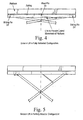
- FIGURE 4 shows a four sliding pin scissors lift in a fully retracted configuration
- FIGURE 5 shows the scissors lift of FIGURE 4 in a partially elevated configuration
- FIGURE 6 is a schematic illustration of a single shear load sensing pin
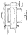
- FIGURE 7 is a schematic illustration of a double shear load sensing pin
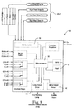
- FIGURE 8 is a schematic circuit diagram of an interface module.
- a scissors lift 10 typically includes a frame or chassis 12 supported by a plurality of wheels 14.
- a drive mechanism 16 provides motive power for the wheels 14.
- a scissors arm assembly 18 is secured at one end to the frame 12 and at an opposite end to a platform 20.
- An internal lift mechanism expands and contracts the scissors arm assembly 18 to raise and lower the platform, respectively.
- the platform 20 is secured to the scissors arm assembly 18 via a plurality of load sensing pins 22, 24 (see FIGURES 2, 3) that detect a vertical load on the platform 20.
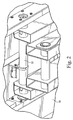
- FIGURES 2 and 3 show an underside view of the platform 20, illustrating the fixed load sensing pins 22 (FIGURE 2) and the sliding load sensing pins 24 (FIGURE 3).
- the ends of the scissors arm assembly 18 are necessarily shifted toward each other.
- Conventional pins are replaced with the load sensing pins 22, 24 according to the invention. That is, the load sensing pins 22, 24 are constructed of a length and diameter substantially identical to the conventional pivot pins.
- the force sensing pins 22, 24 measure the vertical force placed upon them by all external loads and forces applied to the platform 20.
- a fixed load sensing pin 22 is shown in FIGURE 2
- a sliding load sensing pin 24 is shown in FIGURE 3.
- the sliding pins 24 accommodate rotary motion of the scissors arms 18 while maintaining the load on each pin in a vertical orientation.
- a certain weight on the platform 20 creates variable loads on the pins 22, 24 when the lift is raised or lowered. This is because the pins 22, 24 move relative to the platform 20 and reactions change accordingly. A total reading, however, should remain constant.
- the sliding pins 24 are installed in sliding blocks or bearings 25. The blocks have to be retained to prevent rotation, thus permitting the pins 24 to maintain a vertical orientation.
- both fixed 22 and sliding 24 load pins are constrained rotationally to the platform 20 so that the sensing axis is always vertical.
- Such mounting is mandated by the fact that the pins 22, 24 measure load in one particular direction, which in this application, preferably coincides with gravity direction (vertical).
- Such method of retaining the pins is not always the case for scissors with traditional structural pins. Indeed, some pins are secured to the arm assembly and therefore rotate about the platform. In such scissors, a redesign may be mandated.
- all four pins 24' are of the sliding type.
- two additional small pins 25 are added to the platform to prevent its lateral movement.
- These pins 25 carry minimal vertical load and therefore can be ignored.
- the load on the pins 25 can be estimated via strain gauges for example (vertical and horizontal forces can be derived for the arms angle) or measured accurately via load pins.
- These pins 24' can either be single axis or dual axis, depending on the magnitude of the horizontal force. Alternatively, a single axis pin attached to the link in addition to measuring the arms angle is sufficient to predict the vertical force on them.
- FIGURE 4 shows the alternative arrangement in a fully retracted configuration
- FIGURE 5 shows the arrangement in a partially elevated configuration.
- the system includes a combination of load sensing pins and traditional structural pins.
- the load on one or two pins may be constant, or may vary in accordance to some known relation, etc. Measuring the load at few pins may be enough to predict the load in the platform. Additional consideration can be made to the possibility of using less than four sensing pins, with the remaining pins being conventional structural pins.
- the length and diameter of the load sensing pins are preferably kept identical to conventional pins. Indeed, for homogenization and cost savings, all load sensing pins will be of same length and same diameter (or two diameters) regardless of the scissor model. Traditionally, entire pins of a specific machine are of the same diameter. This includes pins in the arm assembly itself and at the connection of the arm assembly with the frame. This approach leads to substantially over-designed pins at the connection of the arm assembly with the platform (i.e., pins being monitored). These pins carry in general the smallest load. It was therefore judged for sake of cost savings (not to design several load sensing pins with different lengths and diameters) to redesign pins to adequately fit most if not all scissor models.
- FIGURES 6 and 7. An explanation of how the pins perform their intended-function can be given with reference to FIGURES 6 and 7. As a brief explanation, there is in the pin at least one shear area (reduced diameter area) where shear is predominant. By judiciously inserting strain gages in the shear zone, the magnitude of the applied force can be determined. Pins could have two shear areas, one on each end of the pin as shown in FIGURE 7.
- the first type of pin shown in FIGURE 6 is referred to as a "single shear pin,” and the second type is referred to as a “double shear pin.”
- Sliding pins 24 maintain the load in a vertical orientation because first the pins are secured rotationally to the sliding block 25 so that the sensing axis is always vertical, and second the maximum generated horizontal force is equal to the friction between the slide blocks and the rails. Obviously this friction force is kept to a strict minimum by design, and therefore the loading on the sliding pins is substantially vertical. Due to equilibrium, the horizontal force on the fixed pins is equal and opposite to the friction force on the sliding pins. Using same argument, the load on the fixed pins is also substantially vertical.
- the load sensing pins 22, 24 communicate with an electronic interface module 30 that assesses the loading state of the machine by monitoring the sum of the four sensors 22, 24.
- the electronic interface module 30 communicates with the lift mechanism and controls operation of the lift mechanism according to the signals from the load sensing pins 22, 24.
- the electronic interface module 30 includes a microprocessor 32 that carries out a control program stored in the system memory 34.
- An A/D converter 36 converts the signals from the load sensing pins 22, 24 for processing by the microprocessor 32.
- a tilt sensor 37 may be secured to one of the frame 12 or the platform 20 and communicates with the microprocessor 32.
- the tilt sensor 37 detects an tilt of the scissors lift machine, and the microprocessor 32 adjusts the signals from the load sensing pins 22, 24 according to the detected out of level angle.
- the tilt sensor 37 is generally provided to assess the inclination or tilt of the machine. By regulation, if the tilt is higher than a certain predetermined angle (typically 2 to 5 deg.) all functions should be cut. This tilt or angle sensor 37 can be used to correct the load pin readings. Another possibility is to attach the angle sensor 37 to the platform 20 in order to assess the true tilt of the platform (which includes arms sway) and correct the load reading accordingly.
- Another angle sensor may be used to detect arms angle and consequently platform elevation. Information from this angle sensor can be used to calculate center of gravity of the loaded platform and control overload of a deck extension. Alternatively, a direct measure (via cable reel for example) of the distance between the fixed and sliding pins may be sufficient.
- Relays may be provided to permit control of the different type of machines with the same electronic interface module.
- Some machines are microprocessor based and others are electro-mechanical, which could either be electric or engine powered.
- the interface module 30 controls operation of the driving mechanism and lift vehicle functions according to signals from the load sensing pins 22, 24.
- the system can be conformed to an anticipated new safety regulation in Europe.
- the interface module 30 prevents any normal movement of the work platform 20 from a stationary working position after a rated load is reached and before, e.g., 120% of the rated load is exceeded.
- a warning consisting of a continuously flashing red light via the lamp output driver and red warning lamp 38 together with an acoustic signal via the alarm output driver and audible alarm 40 is activated by the microprocessor 32.
- the light continues to flash as long as normal movement is prevented according to the detected platform load, and the acoustic alarm is programmed to sound for periods of at least five seconds repeated every minute. Movement can only restart if the platform overload is removed.
- the system can be programmed to effect operation according to numerous parameters, and the invention is not necessarily meant to be limited to the described exemplary application.
- the interface module 30 additionally provides for dynamic load monitoring, which exceeds the static monitoring requirements of known regulations including the noted anticipated safety regulation in Europe. That is, with an arrangement dedicated to static monitoring requirements, the system typically allows the load to settle once the lift is stationary prior to recalculating the load condition.
- the interface module 30 of the present invention has the ability (in addition to static measurements) to provide constant "dynamic" monitoring, thereby preventing the possibility of overloading the platform while the platform is in motion.
- provisions can be embedded into the operation of the interface module 30 to monitor and/or prevent the occurrence of crushing, either in the platform or underneath the platform.
- the interface module can be programmed to detect load increases or decreases over time such that if the platform encounters an obstruction as the platform is being raised, the system can detect a sudden increase in load over a short period of time and immediately shut down and/or back off the raising platform. On the other hand, if the platform encounters an obstruction as it is being lowered, the interface module 30 would detect a sudden decrease in load via the load sensing pins 22, 24 and immediately stop the platform.
- the interface module 30 can flag events that may affect the accuracy of the load sensing pins 22, 24. For example, if the load exceeds some predetermined pin yield force, the load sensing pins 22, 24 may be displaced into a false reading. If such a load is detected, the system can alert the operator to inspect the load sensing pins.
- the sliding pins 24 necessarily change their position relative to the platform load.
- readings from the load sensing pins 22, 24 can be processed to determine a center of gravity of the load. In this manner, a stability condition can be determined.
- This functionality can be particularly advantageous if a deck extension (including dual deck extension arrangements) is used with the lifting platform.
- the size and diameter of the sensing pins can be kept identical to the conventional pins they replace, assembly is easy and design changes are kept to a strict minimum.
- the system does not incorporate additional parts to measure the load, as is the case with load cells and the like, but rather merely adapts existing parts to perform additional functions.
Landscapes
- Life Sciences & Earth Sciences (AREA)
- Engineering & Computer Science (AREA)
- Geology (AREA)
- Mechanical Engineering (AREA)
- Structural Engineering (AREA)
- Forklifts And Lifting Vehicles (AREA)
Applications Claiming Priority (2)
| Application Number | Priority Date | Filing Date | Title |
|---|---|---|---|
| US236911 | 2002-09-09 | ||
| US10/236,911 US7493987B2 (en) | 2002-09-09 | 2002-09-09 | Platform load sensing for vertical lifts |
Publications (2)
| Publication Number | Publication Date |
|---|---|
| EP1396468A1 true EP1396468A1 (de) | 2004-03-10 |
| EP1396468B1 EP1396468B1 (de) | 2007-08-22 |
Family
ID=31715327
Family Applications (1)
| Application Number | Title | Priority Date | Filing Date |
|---|---|---|---|
| EP03251818A Expired - Lifetime EP1396468B1 (de) | 2002-09-09 | 2003-03-22 | Hebebühne mit Lastmessung |
Country Status (4)
| Country | Link |
|---|---|
| US (1) | US7493987B2 (de) |
| EP (1) | EP1396468B1 (de) |
| CA (1) | CA2419358C (de) |
| DE (1) | DE60315773T2 (de) |
Cited By (8)
| Publication number | Priority date | Publication date | Assignee | Title |
|---|---|---|---|---|
| NL1029286C2 (nl) * | 2005-06-17 | 2006-12-19 | Haak Martin Jan | Hefinrichting, alsmede lastmeetsysteem. |
| WO2010037999A1 (en) | 2008-09-30 | 2010-04-08 | Niftylift Limited | Load monitoring system |
| WO2010118481A3 (en) * | 2009-04-17 | 2010-12-02 | Allenbroer Leo Alix De Lille | Multifunctional basket with improved properties |
| EP2479135B1 (de) * | 2011-01-21 | 2016-05-11 | California Manufacturing Engineering Company LLC | Hubarbeitsvorrichtung mit seitlich versetzter Arbeitsbühne |
| FR3105202A1 (fr) | 2019-12-23 | 2021-06-25 | Haulotte Group | Nacelle élévatrice à ciseaux et procédé de détermination de la stabilité d’une telle nacelle |
| US20230286786A1 (en) * | 2022-03-10 | 2023-09-14 | Zhejiang Dingli Machinery Co., Ltd. | Scissor aerial work platform and scissor lifting assembly thereof |
| EP4332050A1 (de) * | 2022-08-30 | 2024-03-06 | Zhejiang Dingli Machinery Co., LTD. | Scherenhubarbeitsbühne und scherenhubanordnung dafür |
| WO2025036898A1 (fr) * | 2023-08-14 | 2025-02-20 | Haulotte Group | Méthode d'alerte pour une nacelle élévatrice, notamment une nacelle articulée, et nacelle élévatrice associée |
Families Citing this family (25)
| Publication number | Priority date | Publication date | Assignee | Title |
|---|---|---|---|---|
| US7802652B2 (en) * | 2006-03-13 | 2010-09-28 | Aluminum Ladder Company | Servicing station for tractor trailer trucks |
| DE102006037107A1 (de) * | 2006-08-07 | 2008-02-14 | Claas Fertigungstechnik Gmbh | Arbeitsbühne |
| US10358331B2 (en) * | 2010-12-20 | 2019-07-23 | Jlg Industries, Inc. | Work platform with protection against sustained involuntary operation |
| CA2592494A1 (en) * | 2007-06-12 | 2008-12-12 | Alden Heppner | Elevated observatory |
| US8141681B2 (en) | 2008-04-07 | 2012-03-27 | Safeworks, Llc | Tower climbing assist device |
| US8505684B1 (en) | 2009-02-05 | 2013-08-13 | Marc Bogue | Aerial work platform apparatus and method |
| US8292265B2 (en) * | 2009-07-17 | 2012-10-23 | Benzing James T | Mobile support apparatus |
| FR3002799B1 (fr) * | 2013-03-01 | 2015-07-31 | Haulotte Group | Cellule de mesure d'effort pour nacelle elevatrice et nacelle elevatrice comprenant une telle cellule |
| EP2993332B1 (de) | 2013-12-17 | 2021-11-03 | Komatsu Ltd. | Nutzfahrzeug und verfahren zur steuerung davon |
| US10118810B2 (en) * | 2014-01-27 | 2018-11-06 | Xtreme Manufacturing, Llc | Method and system for a low height lift device |
| US10167181B2 (en) * | 2016-07-22 | 2019-01-01 | Chejiang Dingli Machinery Co., Ltd. | Hydraulic steering shear-fork type aerial work platform |
| US11215495B2 (en) * | 2017-01-25 | 2022-01-04 | Jlg Industries, Inc. | Pressure based load sensing system |
| US10467932B1 (en) | 2017-04-06 | 2019-11-05 | Kooima Company | Mobile elevating apparatus |
| US10991279B1 (en) | 2017-04-06 | 2021-04-27 | Kooima Ag, Inc. | Mobile elevating apparatus |
| US10519014B2 (en) | 2017-06-30 | 2019-12-31 | Mezzanine Safeti-Gates, Inc. | Safety barrier for loading dock lift |
| USD856623S1 (en) * | 2017-07-13 | 2019-08-13 | Jcb Access Limited | Scissor lift |
| USD859773S1 (en) * | 2017-07-13 | 2019-09-10 | Jcb Access Limited | Scissor lift |
| FR3087762A1 (fr) | 2018-10-26 | 2020-05-01 | Haulotte Group | Systeme de pesage pour plate-forme de travail d’une nacelle elevatrice a mat |
| US12234728B2 (en) * | 2019-05-13 | 2025-02-25 | Vermeer Manufacturing Company | Horizontal directional drilling system with operator lift |
| USD984775S1 (en) * | 2020-03-19 | 2023-04-25 | Terex South Dakota, Inc. | Combined lift vehicle and chassis |
| USD984774S1 (en) * | 2020-03-19 | 2023-04-25 | Terex South Dakota, Inc. | Combined lift vehicle or chassis |
| US20210354968A1 (en) * | 2020-05-14 | 2021-11-18 | Terex South Dakota, Inc. | Load detection for an aerial lift assembly |
| US12486151B2 (en) * | 2022-03-02 | 2025-12-02 | Miller Chibueze Anyogu | Mobile elevated surveillance tower |
| US20230399215A1 (en) * | 2022-06-14 | 2023-12-14 | Microsoft Technology Licensing, Llc | Lift with swiveling and horizontally sliding platform |
| KR102859747B1 (ko) * | 2022-12-21 | 2025-09-15 | 한화시스템 주식회사 | 시험 장치 및 시험 방법 |
Citations (7)
| Publication number | Priority date | Publication date | Assignee | Title |
|---|---|---|---|---|
| GB2031594A (en) * | 1978-09-18 | 1980-04-23 | Ferodo Sa | Monitoring forces in a load- handling boom |
| GB2062258A (en) * | 1979-11-01 | 1981-05-20 | Simon Eng Dudley Ltd | Safe Load Indicator |
| DE3045196A1 (de) * | 1980-12-01 | 1982-07-08 | Trepel Ag, 6200 Wiesbaden | Hebevorrichtung |
| DE3711239A1 (de) * | 1986-04-04 | 1987-10-15 | Voest Alpine Ag | Einrichtung zur sicherung von verfahrbaren ladegeraeten |
| FR2732001A1 (fr) * | 1995-03-24 | 1996-09-27 | Manitou Bf | Dispositif elevateur de personnel |
| FR2733493A1 (fr) * | 1995-04-26 | 1996-10-31 | Const A Haulotte Atel | Systeme de securite pour engins elevateurs du type a nacelle, a plate-forme ou similaire |
| EP1186568A1 (de) * | 2000-09-12 | 2002-03-13 | Pinguely-Haulotte | Hubarbeitsbühne und Verfahren zum Steuern einer sich darauf befindenden Last |
Family Cites Families (11)
| Publication number | Priority date | Publication date | Assignee | Title |
|---|---|---|---|---|
| DE1166991B (de) | 1962-10-26 | 1964-04-02 | Trepel K G Maschinenfabrik | Hydraulisch angetriebener Hebetisch |
| US3695096A (en) | 1970-04-20 | 1972-10-03 | Ali Umit Kutsay | Strain detecting load cell |
| US3920096A (en) | 1974-07-01 | 1975-11-18 | Upright Inc | Vertical hydraulic ram system for scissors assembly scaffold |
| SE419211B (sv) | 1978-12-15 | 1981-07-20 | Jan Axel Gunnar Ekman | Anordning for styrning av luftsystem |
| US4326601A (en) | 1980-05-30 | 1982-04-27 | Jlg Industries, Inc. | Aerial lift platform apparatus with capacity indicator |
| US4833615A (en) | 1986-10-15 | 1989-05-23 | A.G.A. Credit | System for the protection of an aerial device having a pivotable boom |
| US4930598A (en) * | 1988-07-25 | 1990-06-05 | 501 Sky Climber, Inc. | Scissors lift apparatus |
| CA2032983C (en) * | 1990-12-21 | 1999-09-07 | Allan Bowman | Load measuring system for refuse trucks |
| US5992562A (en) * | 1996-01-26 | 1999-11-30 | Jlg Industries, Inc. | Scissor lift control apparatus |
| US6234508B1 (en) * | 1999-09-03 | 2001-05-22 | Case Corporation | Upper link sensing |
| US6985795B2 (en) * | 2001-09-21 | 2006-01-10 | Schlage Lock Company | Material handler with center of gravity monitoring system |
-
2002
- 2002-09-09 US US10/236,911 patent/US7493987B2/en not_active Expired - Lifetime
-
2003
- 2003-02-20 CA CA2419358A patent/CA2419358C/en not_active Expired - Lifetime
- 2003-03-22 EP EP03251818A patent/EP1396468B1/de not_active Expired - Lifetime
- 2003-03-22 DE DE60315773T patent/DE60315773T2/de not_active Expired - Lifetime
Patent Citations (7)
| Publication number | Priority date | Publication date | Assignee | Title |
|---|---|---|---|---|
| GB2031594A (en) * | 1978-09-18 | 1980-04-23 | Ferodo Sa | Monitoring forces in a load- handling boom |
| GB2062258A (en) * | 1979-11-01 | 1981-05-20 | Simon Eng Dudley Ltd | Safe Load Indicator |
| DE3045196A1 (de) * | 1980-12-01 | 1982-07-08 | Trepel Ag, 6200 Wiesbaden | Hebevorrichtung |
| DE3711239A1 (de) * | 1986-04-04 | 1987-10-15 | Voest Alpine Ag | Einrichtung zur sicherung von verfahrbaren ladegeraeten |
| FR2732001A1 (fr) * | 1995-03-24 | 1996-09-27 | Manitou Bf | Dispositif elevateur de personnel |
| FR2733493A1 (fr) * | 1995-04-26 | 1996-10-31 | Const A Haulotte Atel | Systeme de securite pour engins elevateurs du type a nacelle, a plate-forme ou similaire |
| EP1186568A1 (de) * | 2000-09-12 | 2002-03-13 | Pinguely-Haulotte | Hubarbeitsbühne und Verfahren zum Steuern einer sich darauf befindenden Last |
Cited By (16)
| Publication number | Priority date | Publication date | Assignee | Title |
|---|---|---|---|---|
| NL1029286C2 (nl) * | 2005-06-17 | 2006-12-19 | Haak Martin Jan | Hefinrichting, alsmede lastmeetsysteem. |
| EP1733994A1 (de) * | 2005-06-17 | 2006-12-20 | Haak, Martin Jan | Hebevorrichtung, sowie eine Hublastmesseinrichtung |
| WO2010037999A1 (en) | 2008-09-30 | 2010-04-08 | Niftylift Limited | Load monitoring system |
| AU2009299639B2 (en) * | 2008-09-30 | 2012-08-09 | Niftylift Limited | Load monitoring system |
| US8584800B2 (en) | 2008-09-30 | 2013-11-19 | Niftylift Limited | Load monitoring system |
| WO2010118481A3 (en) * | 2009-04-17 | 2010-12-02 | Allenbroer Leo Alix De Lille | Multifunctional basket with improved properties |
| BE1018593A5 (nl) * | 2009-04-17 | 2011-04-05 | Lille Allenbroer Leo Alix De | Multifunctionele werkkooi met verbeterde eigenschappen. |
| EP2479135B1 (de) * | 2011-01-21 | 2016-05-11 | California Manufacturing Engineering Company LLC | Hubarbeitsvorrichtung mit seitlich versetzter Arbeitsbühne |
| FR3105202A1 (fr) | 2019-12-23 | 2021-06-25 | Haulotte Group | Nacelle élévatrice à ciseaux et procédé de détermination de la stabilité d’une telle nacelle |
| WO2021130209A1 (fr) | 2019-12-23 | 2021-07-01 | Haulotte Group | Nacelle élévatrice à ciseaux et procédé de détermination de la stabilité d'une telle nacelle |
| AU2020412747B2 (en) * | 2019-12-23 | 2025-12-18 | Haulotte Group | Scissor lift platform and method for determining the stability of such a platform |
| US20230286786A1 (en) * | 2022-03-10 | 2023-09-14 | Zhejiang Dingli Machinery Co., Ltd. | Scissor aerial work platform and scissor lifting assembly thereof |
| US11787675B2 (en) * | 2022-03-10 | 2023-10-17 | Zhejiang Dingli Machinery Co., Ltd. | Scissor aerial work platform and scissor lifting assembly thereof |
| EP4332050A1 (de) * | 2022-08-30 | 2024-03-06 | Zhejiang Dingli Machinery Co., LTD. | Scherenhubarbeitsbühne und scherenhubanordnung dafür |
| WO2025036898A1 (fr) * | 2023-08-14 | 2025-02-20 | Haulotte Group | Méthode d'alerte pour une nacelle élévatrice, notamment une nacelle articulée, et nacelle élévatrice associée |
| FR3152149A1 (fr) * | 2023-08-14 | 2025-02-21 | Haulotte Group | Méthode d’alerte pour une nacelle élévatrice, notamment une nacelle articulée, et nacelle élévatrice associée |
Also Published As
| Publication number | Publication date |
|---|---|
| CA2419358A1 (en) | 2004-03-09 |
| DE60315773T2 (de) | 2008-01-24 |
| DE60315773D1 (de) | 2007-10-04 |
| CA2419358C (en) | 2010-02-16 |
| EP1396468B1 (de) | 2007-08-22 |
| US7493987B2 (en) | 2009-02-24 |
| US20040045768A1 (en) | 2004-03-11 |
Similar Documents
| Publication | Publication Date | Title |
|---|---|---|
| US7493987B2 (en) | Platform load sensing for vertical lifts | |
| EP2329237B1 (de) | Lastüberwachungssystem | |
| CA2123065C (en) | Lifting apparatus including overload sensing device | |
| EP2668476B1 (de) | Verfahren zur kontrollwägung eines wiegesystems sowie softwareprodukt und anordnung zur kontrollwägung eines wiegesystems und materialfördermittel | |
| CN1246557C (zh) | 有稳定性监控的自走式施工机械 | |
| EP3363765A1 (de) | Stützausleger für selbstfahrende arbeitsmaschinen | |
| EP1346943B1 (de) | Messsystem und Verfahren zur Bewertung der Stabilität eines Hubfahrzeugs | |
| KR20090069823A (ko) | 로울러형 하중검출장치를 이용한 크레인의 안전제어시스템 | |
| KR100714730B1 (ko) | 고소작업차의 다중 안전제어시스템 | |
| US5994650A (en) | Safety system for lift trucks | |
| US6186280B1 (en) | Lift safety system | |
| JPS60188592A (ja) | 上昇および伸張が可能な構造物の制御装置 | |
| KR101862082B1 (ko) | 안전성이 강화된 고소작업 차량 및 그 제어 방법 | |
| KR101840283B1 (ko) | 고소작업 차량 및 그 제어 방법 | |
| JP4874563B2 (ja) | アウトリガの安全装置 | |
| JPH0710468A (ja) | 物体移動装置 | |
| JP4028609B2 (ja) | 傾斜荷台付き車両の積載物の重量測定装置 | |
| JP5610748B2 (ja) | クレーンの過負荷防止装置の制御方法 | |
| JP3066993U (ja) | 作業車の耐久性判断装置 | |
| KR20090080369A (ko) | 고소작업차 과하중 방지장치 | |
| AU2024324609A1 (en) | Alert method for an aerial lift, in particular an articulated lift, and associated aerial lift | |
| JP2000007283A (ja) | 移動式クレーンの軸力による異常判定装置 | |
| US20050225450A1 (en) | Platform assembly | |
| JPH11301996A (ja) | ブーム作業車の安全装置 | |
| CN119942722A (zh) | 一种用于梯子的智能安全风险报警方法及装置 |
Legal Events
| Date | Code | Title | Description |
|---|---|---|---|
| PUAI | Public reference made under article 153(3) epc to a published international application that has entered the european phase |
Free format text: ORIGINAL CODE: 0009012 |
|
| AK | Designated contracting states |
Kind code of ref document: A1 Designated state(s): AT BE BG CH CY CZ DE DK EE ES FI FR GB GR HU IE IT LI LU MC NL PT RO SE SI SK TR |
|
| AX | Request for extension of the european patent |
Extension state: AL LT LV MK |
|
| 17P | Request for examination filed |
Effective date: 20040310 |
|
| AKX | Designation fees paid |
Designated state(s): DE FR GB IE IT |
|
| 17Q | First examination report despatched |
Effective date: 20060922 |
|
| GRAP | Despatch of communication of intention to grant a patent |
Free format text: ORIGINAL CODE: EPIDOSNIGR1 |
|
| GRAS | Grant fee paid |
Free format text: ORIGINAL CODE: EPIDOSNIGR3 |
|
| GRAA | (expected) grant |
Free format text: ORIGINAL CODE: 0009210 |
|
| AK | Designated contracting states |
Kind code of ref document: B1 Designated state(s): DE FR GB IE IT |
|
| REG | Reference to a national code |
Ref country code: GB Ref legal event code: FG4D |
|
| REG | Reference to a national code |
Ref country code: IE Ref legal event code: FG4D |
|
| REF | Corresponds to: |
Ref document number: 60315773 Country of ref document: DE Date of ref document: 20071004 Kind code of ref document: P |
|
| ET | Fr: translation filed | ||
| PLBE | No opposition filed within time limit |
Free format text: ORIGINAL CODE: 0009261 |
|
| STAA | Information on the status of an ep patent application or granted ep patent |
Free format text: STATUS: NO OPPOSITION FILED WITHIN TIME LIMIT |
|
| 26N | No opposition filed |
Effective date: 20080526 |
|
| PG25 | Lapsed in a contracting state [announced via postgrant information from national office to epo] |
Ref country code: IE Free format text: LAPSE BECAUSE OF NON-PAYMENT OF DUE FEES Effective date: 20080324 |
|
| REG | Reference to a national code |
Ref country code: FR Ref legal event code: PLFP Year of fee payment: 14 |
|
| REG | Reference to a national code |
Ref country code: FR Ref legal event code: PLFP Year of fee payment: 15 |
|
| REG | Reference to a national code |
Ref country code: FR Ref legal event code: PLFP Year of fee payment: 16 |
|
| PGFP | Annual fee paid to national office [announced via postgrant information from national office to epo] |
Ref country code: GB Payment date: 20220321 Year of fee payment: 20 Ref country code: DE Payment date: 20220322 Year of fee payment: 20 |
|
| PGFP | Annual fee paid to national office [announced via postgrant information from national office to epo] |
Ref country code: IT Payment date: 20220322 Year of fee payment: 20 Ref country code: FR Payment date: 20220322 Year of fee payment: 20 |
|
| REG | Reference to a national code |
Ref country code: DE Ref legal event code: R071 Ref document number: 60315773 Country of ref document: DE |
|
| REG | Reference to a national code |
Ref country code: GB Ref legal event code: PE20 Expiry date: 20230321 |
|
| PG25 | Lapsed in a contracting state [announced via postgrant information from national office to epo] |
Ref country code: GB Free format text: LAPSE BECAUSE OF EXPIRATION OF PROTECTION Effective date: 20230321 |
|
| P01 | Opt-out of the competence of the unified patent court (upc) registered |
Effective date: 20230507 |