EP1399204B1 - Verfahren und Vorrichtung zur Erfassung der Abtrennung der venösen Nadel von einem Patienten während der Dialyse - Google Patents
Verfahren und Vorrichtung zur Erfassung der Abtrennung der venösen Nadel von einem Patienten während der Dialyse Download PDFInfo
- Publication number
- EP1399204B1 EP1399204B1 EP02738460A EP02738460A EP1399204B1 EP 1399204 B1 EP1399204 B1 EP 1399204B1 EP 02738460 A EP02738460 A EP 02738460A EP 02738460 A EP02738460 A EP 02738460A EP 1399204 B1 EP1399204 B1 EP 1399204B1
- Authority
- EP
- European Patent Office
- Prior art keywords
- venous
- signal
- pressure
- arterial
- branch
- Prior art date
- Legal status (The legal status is an assumption and is not a legal conclusion. Google has not performed a legal analysis and makes no representation as to the accuracy of the status listed.)
- Expired - Lifetime
Links
- 238000000502 dialysis Methods 0.000 title claims abstract description 36
- 238000000034 method Methods 0.000 title claims abstract description 22
- 210000004369 blood Anatomy 0.000 claims abstract description 44
- 239000008280 blood Substances 0.000 claims abstract description 44
- 230000004872 arterial blood pressure Effects 0.000 claims abstract description 34
- 230000007423 decrease Effects 0.000 claims abstract description 27
- 230000002572 peristaltic effect Effects 0.000 claims description 20
- 230000017531 blood circulation Effects 0.000 claims description 13
- 230000002596 correlated effect Effects 0.000 claims description 10
- 230000000875 corresponding effect Effects 0.000 claims description 9
- 238000009795 derivation Methods 0.000 claims description 6
- 230000000007 visual effect Effects 0.000 claims description 4
- 238000006243 chemical reaction Methods 0.000 claims description 2
- 230000001419 dependent effect Effects 0.000 claims 1
- 238000005259 measurement Methods 0.000 description 9
- 210000000748 cardiovascular system Anatomy 0.000 description 7
- 206010016717 Fistula Diseases 0.000 description 4
- 230000003890 fistula Effects 0.000 description 4
- 239000000463 material Substances 0.000 description 3
- 239000012528 membrane Substances 0.000 description 3
- 230000008878 coupling Effects 0.000 description 2
- 238000010168 coupling process Methods 0.000 description 2
- 238000005859 coupling reaction Methods 0.000 description 2
- 230000001939 inductive effect Effects 0.000 description 2
- 238000002347 injection Methods 0.000 description 2
- 239000007924 injection Substances 0.000 description 2
- 239000007788 liquid Substances 0.000 description 2
- 239000002245 particle Substances 0.000 description 2
- 208000001647 Renal Insufficiency Diseases 0.000 description 1
- 230000004913 activation Effects 0.000 description 1
- 230000033228 biological regulation Effects 0.000 description 1
- 210000000601 blood cell Anatomy 0.000 description 1
- 238000009792 diffusion process Methods 0.000 description 1
- 201000006370 kidney failure Diseases 0.000 description 1
- 238000012544 monitoring process Methods 0.000 description 1
- 230000003071 parasitic effect Effects 0.000 description 1
- 210000002381 plasma Anatomy 0.000 description 1
- 230000002792 vascular Effects 0.000 description 1
- 238000004804 winding Methods 0.000 description 1
Images

Classifications
-
- A—HUMAN NECESSITIES
- A61—MEDICAL OR VETERINARY SCIENCE; HYGIENE
- A61M—DEVICES FOR INTRODUCING MEDIA INTO, OR ONTO, THE BODY; DEVICES FOR TRANSDUCING BODY MEDIA OR FOR TAKING MEDIA FROM THE BODY; DEVICES FOR PRODUCING OR ENDING SLEEP OR STUPOR
- A61M1/00—Suction or pumping devices for medical purposes; Devices for carrying-off, for treatment of, or for carrying-over, body-liquids; Drainage systems
- A61M1/36—Other treatment of blood in a by-pass of the natural circulatory system, e.g. temperature adaptation, irradiation ; Extra-corporeal blood circuits
- A61M1/3621—Extra-corporeal blood circuits
- A61M1/3639—Blood pressure control, pressure transducers specially adapted therefor
-
- A—HUMAN NECESSITIES
- A61—MEDICAL OR VETERINARY SCIENCE; HYGIENE
- A61M—DEVICES FOR INTRODUCING MEDIA INTO, OR ONTO, THE BODY; DEVICES FOR TRANSDUCING BODY MEDIA OR FOR TAKING MEDIA FROM THE BODY; DEVICES FOR PRODUCING OR ENDING SLEEP OR STUPOR
- A61M1/00—Suction or pumping devices for medical purposes; Devices for carrying-off, for treatment of, or for carrying-over, body-liquids; Drainage systems
- A61M1/36—Other treatment of blood in a by-pass of the natural circulatory system, e.g. temperature adaptation, irradiation ; Extra-corporeal blood circuits
- A61M1/3621—Extra-corporeal blood circuits
- A61M1/3653—Interfaces between patient blood circulation and extra-corporal blood circuit
-
- A—HUMAN NECESSITIES
- A61—MEDICAL OR VETERINARY SCIENCE; HYGIENE
- A61M—DEVICES FOR INTRODUCING MEDIA INTO, OR ONTO, THE BODY; DEVICES FOR TRANSDUCING BODY MEDIA OR FOR TAKING MEDIA FROM THE BODY; DEVICES FOR PRODUCING OR ENDING SLEEP OR STUPOR
- A61M1/00—Suction or pumping devices for medical purposes; Devices for carrying-off, for treatment of, or for carrying-over, body-liquids; Drainage systems
- A61M1/36—Other treatment of blood in a by-pass of the natural circulatory system, e.g. temperature adaptation, irradiation ; Extra-corporeal blood circuits
- A61M1/3621—Extra-corporeal blood circuits
- A61M1/3653—Interfaces between patient blood circulation and extra-corporal blood circuit
- A61M1/3656—Monitoring patency or flow at connection sites; Detecting disconnections
-
- A—HUMAN NECESSITIES
- A61—MEDICAL OR VETERINARY SCIENCE; HYGIENE
- A61M—DEVICES FOR INTRODUCING MEDIA INTO, OR ONTO, THE BODY; DEVICES FOR TRANSDUCING BODY MEDIA OR FOR TAKING MEDIA FROM THE BODY; DEVICES FOR PRODUCING OR ENDING SLEEP OR STUPOR
- A61M1/00—Suction or pumping devices for medical purposes; Devices for carrying-off, for treatment of, or for carrying-over, body-liquids; Drainage systems
- A61M1/36—Other treatment of blood in a by-pass of the natural circulatory system, e.g. temperature adaptation, irradiation ; Extra-corporeal blood circuits
- A61M1/3621—Extra-corporeal blood circuits
- A61M1/367—Circuit parts not covered by the preceding subgroups of group A61M1/3621
-
- A—HUMAN NECESSITIES
- A61—MEDICAL OR VETERINARY SCIENCE; HYGIENE
- A61M—DEVICES FOR INTRODUCING MEDIA INTO, OR ONTO, THE BODY; DEVICES FOR TRANSDUCING BODY MEDIA OR FOR TAKING MEDIA FROM THE BODY; DEVICES FOR PRODUCING OR ENDING SLEEP OR STUPOR
- A61M39/00—Tubes, tube connectors, tube couplings, valves, access sites or the like, specially adapted for medical use
- A61M39/10—Tube connectors; Tube couplings
- A61M2039/1005—Detection of disconnection
-
- A—HUMAN NECESSITIES
- A61—MEDICAL OR VETERINARY SCIENCE; HYGIENE
- A61M—DEVICES FOR INTRODUCING MEDIA INTO, OR ONTO, THE BODY; DEVICES FOR TRANSDUCING BODY MEDIA OR FOR TAKING MEDIA FROM THE BODY; DEVICES FOR PRODUCING OR ENDING SLEEP OR STUPOR
- A61M2205/00—General characteristics of the apparatus
- A61M2205/13—General characteristics of the apparatus with means for the detection of operative contact with patient, e.g. lip sensor
-
- A—HUMAN NECESSITIES
- A61—MEDICAL OR VETERINARY SCIENCE; HYGIENE
- A61M—DEVICES FOR INTRODUCING MEDIA INTO, OR ONTO, THE BODY; DEVICES FOR TRANSDUCING BODY MEDIA OR FOR TAKING MEDIA FROM THE BODY; DEVICES FOR PRODUCING OR ENDING SLEEP OR STUPOR
- A61M2205/00—General characteristics of the apparatus
- A61M2205/33—Controlling, regulating or measuring
- A61M2205/3331—Pressure; Flow
-
- A—HUMAN NECESSITIES
- A61—MEDICAL OR VETERINARY SCIENCE; HYGIENE
- A61M—DEVICES FOR INTRODUCING MEDIA INTO, OR ONTO, THE BODY; DEVICES FOR TRANSDUCING BODY MEDIA OR FOR TAKING MEDIA FROM THE BODY; DEVICES FOR PRODUCING OR ENDING SLEEP OR STUPOR
- A61M5/00—Devices for bringing media into the body in a subcutaneous, intra-vascular or intramuscular way; Accessories therefor, e.g. filling or cleaning devices, arm-rests
- A61M5/14—Infusion devices, e.g. infusing by gravity; Blood infusion; Accessories therefor
- A61M5/168—Means for controlling media flow to the body or for metering media to the body, e.g. drip meters, counters ; Monitoring media flow to the body
- A61M5/16831—Monitoring, detecting, signalling or eliminating infusion flow anomalies
Definitions
- the present invention relates to a method of detecting the detachment of the venous needle from a patient during an extracorporeal blood treatment in a dialysis machine.
- blood consists of a liquid component, called the blood plasma and a corpuscular component formed by the blood cells, including the red corpuscles among other components.
- the blood has, in addition to the aforesaid components, particles of low molecular weight (referred to below as solute) which have to be eliminated by a dialysis treatment carried out with a dialysis machine.
- a dialysis machine of the known type generally comprises an extracorporeal blood circuit, a dialysate circuit and a filter, which is located in the aforesaid circuits and comprises a blood compartment and a dialysate compartment, which are separated from each other by a semi-permeable membrane, and through which pass, respectively, the blood to be treated and the dialysate, generally flowing in counter-current mode.
- the undesired particles contained in the blood migrate from the blood compartment to the dialysate compartment through the semi-permeable membrane both by diffusion and by convection, as a result of the passage of some of the liquid contained in the blood towards the dialysate compartment.
- the patient will have lost some weight by the end of the dialysis process.
- the extracorporeal circuit is connected to the patient by means of an arterial needle and a venous needle, which are inserted into fistulas formed in the patient's cardiovascular system, so that they can, respectively, collect the blood to be treated and return the treated blood to the patient's cardiovascular system.
- the extracorporeal circuit comprises a peristaltic pump and a dropper located in the arterial branch and in the venous branch respectively.
- This method is based on the electrical conductivity of the blood, and consists of the injection of a current into a closed circuit consisting of the extracorporeal circuit and the patient's cardiovascular system, and the measurement, by means of a measuring instrument located in the aforesaid extracorporeal circuit, the current variations which are caused by the detachment of one or both of the needles.
- the current injection and the measurement of the current variation have to be carried out by inductive coupling, in other words by means of windings located at specified points along the extracorporeal blood circuit.
- this method does not allow for the fact that the patient may be connected to earth and that the filter itself is necessarily connected to earth, since the dialysate circuit is connected to earth to meet the requirements of the safety regulations for dialysis machines. Therefore the electrical circuit assumed in the aforesaid application does not truly represent the real analogy of a dialysis machine in electrical terms.
- the object of the present invention is to provide a method of detecting the detachment of the venous needle from a patient during an extracorporeal blood treatment in a dialysis machine, which overcomes the drawbacks of the known art.
- a method for detecting the detachment of the venous needle from a patient during an extracorporeal blood treatment in a dialysis machine having an extracorporeal blood circuit comprising an arterial branch and a venous branch, the method comprising the steps of measuring the arterial pressure in the arterial branch and the venous pressure in the venous branch, and determining whether or not essentially simultaneous decreases of the arterial and venous pressures are occurring during the dialysis treatment in normal conditions.
- the present invention also relates to a device for detecting the detachment of the venous needle from a patient during an extracorporeal blood treatment in a dialysis machine.
- a device for detecting the detachment of the venous needle from a patient during an extracorporeal blood treatment in a dialysis machine having an extracorporeal blood circuit comprising an arterial branch and a venous branch, the device being characterized in that it comprises pressure detectors for measuring the arterial pressure in the arterial branch and the venous pressure in the venous branch, and a control unit for determining whether or not decreases of the arterial and venous pressures are occurring during the dialysis treatment in normal conditions.
- control unit evaluates preferably if said decreases of the venous and arterial pressures are occurring in a time interval, which is relatively short (some seconds).
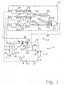
- the number 1 indicates the whole of a dialysis machine connected to a patient P.
- the machine 1 comprises an extracorporeal blood circuit 2, a dialysate circuit 3 and a filter 4, which comprises a blood compartment 5 and a dialysate compartment 6 separated by a semi-permeable membrane 7.
- the extracorporeal blood circuit 2 comprises an arterial branch 8, in which is located a peristaltic pump 9 providing a flow Qb of blood, and a venous branch 10, in which is located a dropper 11.
- the arterial branch 8 has one end connected to the blood compartment 5 and one end provided with an arterial needle 12, which, when in use, is inserted into a fistula (not shown) in the patient P to collect the blood from the cardiovascular system of the patient P, while the branch 10 has one end connected to the blood compartment 5 and an opposite end provided with a venous needle 13, which, when in use, is inserted into the aforesaid fistula (not shown) to return the treated blood to the cardiovascular system of the patient P.
- the branches 8 and 10 are tubes made from plastic material, generally PVC, and are used, respectively, to supply the blood to be treated to the compartment 5 and to introduce the treated blood leaving the compartment 5 into the cardiovascular system.
- the filter 4 and the dropper 11 are also made from plastic material, generally PVC.
- the machine 1 also comprises a device 14 for detecting the detachment of the venous needle 13.
- the operation of the device 14 is based on experimental measurements carried out by the applicant.
- the graphs in Figures 2 to 4 relate to experimental measurements made by the applicant and show a transitory time interval _t1 in which the blood flow Qb is made to vary; two time intervals _t2 and _ t3 in which the blood flow Qb is kept essentially constant; and a time interval _t4 in which the blood flow is reduced to zero, or in other words the dialysis treatment is interrupted.
- the device 14 comprises a control unit 15, a pressure detector 16 located in the arterial branch 8 up-line from the peristaltic pump 9, a pressure detector 17 located in the venous branch 10 near the dropper 11, and an encoder 18 for measuring the speed of revolution of the rotor of the peristaltic pump 9.
- the control unit 15 receives a signal Sr from the encoder 18, correlated with the speed of revolution of the rotor of the peristaltic pump 9, and two signals Spa and SPv, correlated with the arterial pressure Pa and venous pressure Pv, from the two detectors 16 and 17 respectively.
- the unit 15 can process the signals Sr, Spa and SPv, and comprises three derivation units 19p and 19r, which derive the signals Spa, SPv and Sr with respect to time and supply corresponding signals dSpa, dSPv, and dSr, two rectification units 20 for rectifying the derived signals dSPa and dSPv and for supplying two signals RSPa and RSPv, a comparison unit 21, which receives the signal dSR and compares it with an interval I of acceptability stored in a store 22 and emits a digital signal SD1 at the output as a function of the comparison with the interval I of acceptability.
- the unit 15 comprises an adder unit 23, which adds the rectified signals RSPa and RSPv, and emits a signal SA equal to the sum of the rectified signals RSPa and RSPv, a comparison unit 24, which receives the output signal SA. from the adder unit 23, compares the signal SA with a threshold value TV contained in a store 25, and emits a digital signal SD2.
- The' unit 15 also comprises two conversion units 26 for converting the signals RSPa and RSPv into digital signals SD3 and SD4 respectively, and a logical operator unit 27 which receives the digital signals SD1, SD2, SD3 and SD4, compares them with a truth table, and emits a control signal SC.
- the dialysis machine 1 comprises a control unit 28, which is connected to the control unit 15 of the device 14 for receiving the control signal SC, and is also connected to the peristaltic pump 9.
- the unit 28 comprises an acoustic warning device 29 and a visual indicator 30 to alert the operator and user to the detachment of the venous needle 13.'
- the dialysis machine 1 is connected to a patient P as shown schematically in Figure 1.
- the blood flow Qb is kept essentially constant as shown in the graph of Figure 2 in the intervals _t2 and_t3.
- the blood flow Qb varies in an initial time interval_t1, and is then kept constant in successive time intervals _t2 and _t3, until it is brought to zero in the interval _t4 following the detachment of the venous needle 13.
- the graphs of Figures 3 and 4 which have a time scale identical to the time scale, of the graph of Figure 2, show the generally differing trends of the variations of the venous pressure Pv and arterial pressure Pa with a constant flow Qb in the time interval _t2, and the uniform decrease in the venous pressure Pv and arterial pressure Pa in the time interval - t3, during which the venous needle 13 has become detached and the peristaltic pump 9 has not yet been stopped. The peristaltic pump 9 is then stopped and the dialysis treatment is interrupted.to prevent loss of blood from the patient P.
- the speed of revolution of the peristaltic' pump 9. and the arterial pressure Pa and venous pressure Pv are constantly measured by the encoder 18 and by the detectors 16 and 17.
- the speed of revolution of the rotor of the peristaltic pump 9 is correlated with the flow Qb, and this measurement is equivalent for practical purposes to a measurement of the flow Qb, once the characteristics of the pump 9 and the dynamic conditions of the extracorporeal circuit 2 are known.
- the pressure signals SPa and SPb undergo derivation in the corresponding derivation units 19p, and the derived signals dSPa and dSPv are rectified in the corresponding rectification units 20.
- each of the signals RSPa and RSPv takes a value of zero when the corresponding input signal dSPa or dSPv is positive (increasing pressure) and takes a positive value, proportional to the input signal dSPa or dSPv, when the corresponding input signal dSPa or dSPv is negative (falling pressure).
- the derived signal dSr is compared with the interval I of acceptability in the comparison unit 21, which supplies a digital signal SD1 which is equal to one when the derived signal dSr falls within the acceptability interval (constant flow Qb) and is equal to zero when the derived signal dSr falls outside the acceptability interval (variable flow Qb).
- the signal SD1 is equal to one when the flow Qb is essentially constant, and equal to zero when the flow Qb is significantly varied.
- the adder unit 23 adds the rectified signals RSPa and RSPv and compares the sum SA with the threshold value TV, and supplies a digital signal SD2 which is equal to one when the sum SA is greater than the threshold value TV, and a digital signal SD2 which is equal to zero when the sum SA is smaller than the threshold value TV.
- the values of the digital signals SD3 and SD4 are equal to one when the corresponding rectified signals RSPa and RSPv are greater than zero, and equal to zero when the corresponding rectified signals RSPa and RSPv are equal to zero.
- the logical operator unit 27 receives the signals SD1, SD2, SD3 and SD4 and compares these signals with a truth table, and supplies at its output a digital signal SC which is equal to one when all the signals SD1, SD2, SD3 and SD4 are equal to one, while the signal SC takes a value equal to zero when only one of the signals SD1, SD2, SD3 and SD4 is equal to zero. From the practical point of view, with reference to Figures 2 to 4 and to the time interval _t2, the flow Qb is constant and the signal SD1 is equal to one, the rectified signals SD3 and SD4 will both be equal to zero or at least one will be equal to zero.
- the sum SA is less than the threshold value TV, which is selected experimentally to discriminate negligible variations of the arterial pressures Pa and venous pressures Pv from significant variations. Consequently, the signal SC is equal to zero.
- the abrupt decrease of the arterial pressures Pa and venous pressures Pv causes both the signals RSPa and RSPv to be positive and their sum SA to be greater than the threshold value TV.
- the constancy of the flow Qb also causes the signal SD1 to be equal to one, and therefore the signal SC will also be equal to one, which is the value that indicates that the venous needle has become detached.
- the signal SD2 provides a measurement of the degree of the decrease of the arterial pressures Pa and venous pressures Pv and the threshold value TV makes it possible to discriminate the very slight decreases in the aforesaid pressures, which may occur from time to time even without the detachment of the venous needle, from the significant decreases which occur when the venous needle 13 actually becomes detached.
- the signal SC is transmitted to the unit 28, which emits an alarm signal AS to stop the peristaltic pump 9 and the dialysis treatment when SC is equal to one.
- the alarm signal AS can trigger the activation of the acoustic warning device 29 and/or the visual indicator 30.
Landscapes
- Health & Medical Sciences (AREA)
- Heart & Thoracic Surgery (AREA)
- Vascular Medicine (AREA)
- Biomedical Technology (AREA)
- Engineering & Computer Science (AREA)
- Anesthesiology (AREA)
- Cardiology (AREA)
- Hematology (AREA)
- Life Sciences & Earth Sciences (AREA)
- Animal Behavior & Ethology (AREA)
- General Health & Medical Sciences (AREA)
- Public Health (AREA)
- Veterinary Medicine (AREA)
- External Artificial Organs (AREA)
Claims (20)
- Verfahren zur Erfassung der Trennung einer venösen Nadel (13) von einem Patienten (P) während einer extrakorporalen Blutbehandlung in einer Dialysemaschine (1) mit einem extrakorporalen Blutkreislauf (2) umfassend eine arterielle Zweigleitung (8) und eine venöse Zweigleitung (10), wobei das Verfahren die folgenden Schritte umfasst:Messung des arteriellen Druckes (Pa) in der arteriellen Zweigleitung (8) und des venösen Druckes (Pv) in der venösen Zweigleitung (10);Ermitteln, ob Abnahmen der arteriellen Drücke (Pa) und der venösen Drücke (Pv) während der Dialysebehandlung bei normalen Bedingungen stattfinden; undMessung des Blutflusses (Qb) entlang dem extrakorporalen Blutkreislauf (2);dadurch gekennzeichnet, daß eine Überwachung durchgeführt wird, um zu ermitteln, ob der Blutfluss (Qb) in einem Zeitintervall wesentlich konstant ist, bei dem die Abnahmen des arteriellen Druckes (Pa) und des venösen Druckes (Pv) stattgefunden haben.
- Verfahren nach Anspruch 1, dadurch gekennzeichnet, daß der Wert der Abnahmen des arteriellen Druckes (Pa) und des venösen Druckes (Pv) berechnet wird.
- Verfahren nach Anspruch 2, dadurch gekennzeichnet, daß ein Signal (SA), das mit der Summe der Abnahmen des arteriellen Druckes (Pa) und des venösen Druckes (Pv) verbunden ist, mit einem experimentell ermittelten Schwellenwert (TV) verglichen wird.
- Verfahren nach Anspruch 3, dadurch gekennzeichnet, daß ein Warnsignal (AS) ausgegeben wird, wenn alle folgenden Bedingungen im Zeitintervall vorhanden sind:- eine Abnahme des arteriellen Druckes (Pa);- eine Abnahme der venösen Druckes (Pv);- das mit der Summe der Abnahmen des arteriellen Druckes (Pa) und des venösen Druckes (Pv) verbundene Signal (SA) ist höher als der Schwellenwert (TV); und- der Fluss (Qb) ist wesentlich konstant.
- Verfahren nach Anspruch 4, dadurch gekennzeichnet, daß eine akustische Warnvorrichtung (29) und/oder eine visuelle Anzeige (30) durch das Warnsignal (AS) aktiviert wird.
- Vorrichtung zur Erfassung der Trennung einer venösen Nadel (13) von einem Patienten (P) während einer extrakorporalen Blutbehandlung in einer Dialysemaschine (1) mit einem extrakorporalen Blutkreislauf (2) umfassend eine arterielle Zweigleitung (8) und eine venöse Zweigleitung (10), die Vorrichtung (14) umfassend:Druckdetektoren (16, 17) zur Messung des arteriellen Druckes (Pa) in der arteriellen Zweigleitung (8) und des venösen Druckes (Pv) in der venösen Zweigleitung (10);Mittel (18) zur Messung des Blutflusses (Qb) entlang dem extrakorporalen Blutkreislauf (2); undeine Steuereinheit (15) zur Ermittlung, ob Abnahmen der arteriellen Drücke (Pa) und der venösen Drücke (Pv) während der Dialysebehandlung bei normalen Bedingungen stattfinden, und die Steuereinheit (15) umfassend Mittel zur Durchführung einer Überwachung zur Ermittlung, ob der Blutfluss (Qb) in einem Zeitintervall wesentlich konstant ist, bei dem die Abnahmen des arteriellen Druckes (Pa) und des venösen Druckes (Pv) stattgefunden haben.
- Vorrichtung nach Anspruch 6, dadurch gekennzeichnet, daß die Ermittlungsmittel eine Ableitungseinheit (19r) zur Ausgabe eines Signals, das mit der Ableitung des Blutflusses (Qb) verbunden ist, und eine erste Vergleichseinheit (21) zur Ermittlung, ob das mit der Ableitung des Flusses (Qb) sich innerhalb eines Akzeptabilitätsintervalls (I) befindet, umfassen.
- Vorrichtung nach Anspruch 7, dadurch gekennzeichnet, daß die Ableitungseinheit (19r) das Signal Sr zeitabhängig ableitet und ein entsprechendes Signal dSr aussendet, wobei die erste Vergleichseinheit (21) ein digitales Signal SD1 am Ausgang abhängig vom dem Vergleich mit dem Akzeptabilitätsintervall (I) ausgibt.
- Vorrichtung nach irgendeinem der Ansprüche 6 bis 8, dadurch gekennzeichnet, daß die Steuereinheit (15) Mittel (23, 24, 25) zur Diskriminierung des Wertes der Abnahmen des arteriellen Druckes (Pa) und des venösen Druckes (Pv) umfasst.
- Vorrichtung nach Anspruch 9, dadurch gekennzeichnet, daß die Steuereinheit (15) zwei Signale SPa und SPv, die mit dem arteriellen Druck (Pa) und dem venösen Druck (Pv) verbunden sind, jeweils vom ersten und vom zweiten Detektor (16 und 17) empfängt, und daß die Diskriminierungsmittel:- zwei weitere Ableitungseinheiten (19p), die die Signale SPa und SPv zeitabhängig ableiten und entsprechende Signale dSPa und dSPv aussenden;- zwei Berichtigungseinheiten (20) zur Berichtigung der abgeleiteten Signale dSPa und dSPv und zum Aussenden von zwei Signalen RSPa und RSPv;- eine Addiereinheit (23), die die berichtigten Signale RSPa und RSPv addiert und ein Signal (SA) entsprechend der Summe der berichtigten Signale RSPa und RSPv ausgibt; und- zwei Umwandlungseinheiten (26) zur Umwandlung der Signale RSPa und RSPv in entsprechende digitale Signale SD3 und SD4, umfassen.
- Vorrichtung nach Anspruch 9 oder 10, dadurch gekennzeichnet, daß die Steuereinheit (15) eine logische Betriebseinheit (27) umfasst, die ein Steuersignal (SC) abhängig von den Abnahmen des arteriellen Druckes (Pa) und des venösen Druckes (Pv), von dem Ausgangssignal der zweiten Vergleichseinheit (24) und von dem Ausgangssignal der ersten Vergleichseinheit (21) ausgeben kann.
- Vorrichtung nach den Ansprüchen 11, 10 und 8, dadurch gekennzeichnet, daß die zweite Vergleichseinheit (24) das Ausgangssignal (SA) von der Addiereinheit (23) empfängt und ein digitales Signal SD2 abhängig von dem Vergleich des Signals (SA) mit dem Schwellenwert (TV) ausgibt; die logische Betriebseinheit (27), die die digitalen Signale SD1, SD2, SD3 und SD4 empfängt, vergleicht sie mit einer Wahrheitstafel und gibt das Steuersignal (SC) abhängig von dem Vergleich aus.
- Vorrichtung nach irgendeinem der Ansprüche 6 bis 8, dadurch gekennzeichnet, daß die Steuereinheit (15) den Wert der Abnahmen des arteriellen Druckes (Pa) und des venösen Druckes (Pv) berechnet und ein mit der Summe der Abnahmen des arteriellen Druckes (Pa) und des venösen Druckes (Pv) verbundenes Signal (SA) mit einem experimentell ermittelten Schwellenwert (TV) vergleicht.
- Dialysemaschine umfassend eine Steuervorrichtung (14) nach irgendeinem der Ansprüche 6 bis 13, und eine zusätzliche Steuereinheit (28), die ein Steuersignal (SC) von der Steuereinheit (15) empfangen und ein Warnsignal (AS) abhängig von dem Steuersignal (SC) ausgeben kann.
- Maschine nach Anspruch 14, dadurch gekennzeichnet, daß sie eine peristaltische Pumpe (9), die in der arteriellen Zweigleitung (8) angeordnet ist, und eine Pipette (11), die in der venösen Zweigleitung (10) angeordnet ist, umfasst, wobei die peristaltische Pumpe (9) durch das Warnsignal gestoppt werden kann.
- Maschine nach Anspruch 15, dadurch gekennzeichnet, daß die Detektoren (16, 17) einen ersten Detektor (16), der in der arteriellen Zweigleitung (8) aufwärts von der peristaltischen Pumpe (9) angeordnet ist, und einen zweiten Detektor (17), der in der venösen Zweigleitung (10) im Bereich der Pipette (11) angeordnet ist, umfassen.
- Maschine nach irgendeinem der Ansprüche 14 bis 16, dadurch gekennzeichnet, daß die zusätzliche Steuereinheit (28) eine akustische Warnvorrichtung (29) umfasst, die durch das Warnsignal (AS) aktiviert werden kann.
- Maschine nach irgendeinem der Ansprüche 14 bis 17, dadurch gekennzeichnet, daß die zusätzliche Steuereinheit (28) eine visuelle Anzeige (30) umfasst, die durch das Warnsignal aktiviert werden kann.
- Maschine nach irgendeinem der Ansprüche 16, 17 oder der Ansprüche 18, 19 wenn abhängig von Anspruch 16, dadurch gekennzeichnet, daß die Mittel (18) zur Messung des Blutflusses (Qb) einen Encoder (18) zur Messung der Umdrehungsgeschwindigkeit des Rotors der peristaltischen Pumpe (9) umfasst.
- Maschine nach irgendeinem der Ansprüche 14 bis 19, dadurch gekennzeichnet, daß das Warnsignal (AS) ausgegeben wird, wenn alle folgenden Bedingungen im Zeitintervall vorhanden sind:- eine Abnahme des arteriellen Druckes (Pa);- eine Abnahme der venösen Druckes (Pv);- ein mit der Summe der Abnahmen des arteriellen Druckes (Pa) und des venösen Druckes (Pv) verbundenes Signal (SA) ist höher als der Schwellenwert (TV); und- der Blutfluss (Qb) ist wesentlich konstant.
Applications Claiming Priority (3)
| Application Number | Priority Date | Filing Date | Title |
|---|---|---|---|
| IT2001MI001395A ITMI20011395A1 (it) | 2001-06-29 | 2001-06-29 | Metodo e dispositivo di rilevamento del distacco dell'ago venoso da un paziente durante un trattamento extracorporeo del sangue in una macch |
| ITMI20011395 | 2001-06-29 | ||
| PCT/IB2002/002354 WO2003002174A1 (en) | 2001-06-29 | 2002-06-24 | Method and device for detecting the detachment of the venous needle from a patient during dialysis |
Publications (2)
| Publication Number | Publication Date |
|---|---|
| EP1399204A1 EP1399204A1 (de) | 2004-03-24 |
| EP1399204B1 true EP1399204B1 (de) | 2007-02-28 |
Family
ID=11447978
Family Applications (1)
| Application Number | Title | Priority Date | Filing Date |
|---|---|---|---|
| EP02738460A Expired - Lifetime EP1399204B1 (de) | 2001-06-29 | 2002-06-24 | Verfahren und Vorrichtung zur Erfassung der Abtrennung der venösen Nadel von einem Patienten während der Dialyse |
Country Status (7)
| Country | Link |
|---|---|
| US (1) | US7648474B2 (de) |
| EP (1) | EP1399204B1 (de) |
| AT (1) | ATE355092T1 (de) |
| DE (1) | DE60218460T2 (de) |
| ES (1) | ES2283567T3 (de) |
| IT (1) | ITMI20011395A1 (de) |
| WO (1) | WO2003002174A1 (de) |
Cited By (1)
| Publication number | Priority date | Publication date | Assignee | Title |
|---|---|---|---|---|
| WO2015086384A1 (de) | 2013-12-10 | 2015-06-18 | Fresenius Medical Care Deutschland Gmbh | Vorrichtung und verfahren zur überwachung des venösen gefässzugangs bei einer extrakorporalen blutbehandlung |
Families Citing this family (41)
| Publication number | Priority date | Publication date | Assignee | Title |
|---|---|---|---|---|
| ITTO20010582A1 (it) * | 2001-06-15 | 2002-12-15 | Gambro Dasco Spa | Metodo e dispositivo di rilevamento del distacco dell'ago venoso da un paziente durante un trattamento extracorporeo del sangue in una macch |
| US7022098B2 (en) | 2002-04-10 | 2006-04-04 | Baxter International Inc. | Access disconnection systems and methods |
| US7052480B2 (en) | 2002-04-10 | 2006-05-30 | Baxter International Inc. | Access disconnection systems and methods |
| US20040254513A1 (en) | 2002-04-10 | 2004-12-16 | Sherwin Shang | Conductive polymer materials and applications thereof including monitoring and providing effective therapy |
| US10155082B2 (en) | 2002-04-10 | 2018-12-18 | Baxter International Inc. | Enhanced signal detection for access disconnection systems |
| DE102006032815A1 (de) | 2006-07-14 | 2008-01-17 | Fresenius Medical Care Deutschland Gmbh | Verfahren und Vorrichtung zur Überwachung eines extrakorporalen Blutkreislaufs |
| US10463778B2 (en) | 2007-02-09 | 2019-11-05 | Baxter International Inc. | Blood treatment machine having electrical heartbeat analysis |
| US8152751B2 (en) | 2007-02-09 | 2012-04-10 | Baxter International Inc. | Acoustic access disconnection systems and methods |
| US8197431B2 (en) * | 2007-09-21 | 2012-06-12 | Baxter International Inc. | Acoustic access disconnect detection system |
| US9011334B2 (en) * | 2007-09-27 | 2015-04-21 | Baxter International Inc. | Access disconnect detection |
| US9138536B2 (en) | 2008-04-01 | 2015-09-22 | Gambro Lundia Ab | Apparatus and a method for monitoring a vascular access |
| ES2558961T3 (es) | 2008-06-26 | 2016-02-09 | Gambro Lundia Ab | Método y dispositivo para el procesamiento de una señal de medida dependiente del tiempo |
| US10089443B2 (en) | 2012-05-15 | 2018-10-02 | Baxter International Inc. | Home medical device systems and methods for therapy prescription and tracking, servicing and inventory |
| US8192388B2 (en) * | 2008-07-25 | 2012-06-05 | Baxter International Inc. | System and method for detecting access disconnection |
| DE102008057994A1 (de) | 2008-11-19 | 2010-05-27 | Fresenius Medical Care Deutschland Gmbh | Verfahren und Vorrichtung zur Erkennung einer paravasalen Blutung |
| DE102009007806B4 (de) | 2009-02-06 | 2014-06-05 | Fresenius Medical Care Deutschland Gmbh | Vorrichtung zur Schwingungsanregung wenigstens eines Abschnitts einer Gefäßzugangseinrichtung zu deren Überwachung |
| JP5848700B2 (ja) | 2009-05-28 | 2016-01-27 | コーニンクレッカ フィリップス エヌ ヴェKoninklijke Philips N.V. | 血管に対する管の遠位端の位置をモニタリングするための装置 |
| EP2445395B1 (de) | 2009-06-26 | 2017-01-11 | Gambro Lundia AB | Vorrichtungen und verfahren für datenextraktion |
| ES2819027T3 (es) | 2009-11-24 | 2021-04-14 | Fresenius Medical Care Deutschland Gmbh | Procedimiento para la interrupción transitoria de un tratamiento extracorporal de la sangre, dispositivo de control y dispositivo para el tratamiento de la sangre |
| US8753515B2 (en) | 2009-12-05 | 2014-06-17 | Home Dialysis Plus, Ltd. | Dialysis system with ultrafiltration control |
| US10980431B2 (en) | 2009-12-28 | 2021-04-20 | Gambro Lundia Ab | Apparatus and method for prediction of rapid symptomatic blood pressure decrease |
| US8501009B2 (en) | 2010-06-07 | 2013-08-06 | State Of Oregon Acting By And Through The State Board Of Higher Education On Behalf Of Oregon State University | Fluid purification system |
| CN103957960B (zh) | 2011-10-07 | 2016-04-13 | 霍姆透析普拉斯有限公司 | 用于透析系统的热交换流体净化 |
| AU2013201556B2 (en) | 2012-07-13 | 2014-06-05 | Gambro Lundia Ab | Filtering of pressure signals for suppression of periodic pulses |
| CA2899720C (en) | 2013-03-20 | 2021-04-20 | Gambro Lundia Ab | Monitoring of cardiac arrest in a patient connected to an extracorporeal blood processing apparatus |
| DE102013012504B4 (de) | 2013-07-09 | 2021-05-06 | Fresenius Medical Care Deutschland Gmbh | Verfahren zur Überwachung einer extrakorporalen Blutbehandlung und Vorrichtung zur Durchführung des Verfahrens |
| EP2823834B1 (de) | 2013-07-10 | 2016-06-22 | Gambro Lundia | Vorrichtung zur extrakorporalen Blutbehandlung |
| DE102014102731A1 (de) | 2014-02-28 | 2015-09-03 | B. Braun Avitum Ag | Vorrichtung und Verfahren zur Erkennung einer venösen Nadeldiskonnektion |
| DE102014102732A1 (de) | 2014-02-28 | 2015-09-03 | B. Braun Avitum Ag | System und Verfahren zur Erkennung einer venösen Nadeldiskonnektion |
| DE102014102730A1 (de) | 2014-02-28 | 2015-09-03 | B. Braun Avitum Ag | Vorrichtung und Verfahren zur Erkennung eines Fehlers im extrakorporalen Blutkreislauf |
| EP3838308A1 (de) | 2014-04-29 | 2021-06-23 | Outset Medical, Inc. | Dialysesysteme und -verfahren |
| US10413654B2 (en) | 2015-12-22 | 2019-09-17 | Baxter International Inc. | Access disconnection system and method using signal metrics |
| ES2908601T3 (es) | 2016-08-19 | 2022-05-03 | Outset Medical Inc | Sistema y métodos de diálisis peritoneal |
| DE102018106094A1 (de) * | 2018-03-15 | 2019-09-19 | B. Braun Avitum Ag | Sicherungseinrichtung mit Nadeldislokation-Erfassungs- und Absperrmechanismus zum Not-Absperren eines extrakorporalen Blutleitungssystems |
| JP2021533881A (ja) | 2018-08-23 | 2021-12-09 | アウトセット・メディカル・インコーポレイテッドOutset Medical, Inc. | 透析システム及び方法 |
| BR112021021836A2 (pt) | 2019-04-30 | 2022-01-04 | Outset Medical Inc | Métodos para calcular a pressão arterial, para criar dialisato em um sistema de diálise, para medir a porcentagem de rejeição em um sistema de diálise, para coletar e analisar plasma sanguíneo, para remover gás de um circuito extracorpóreo de um sistema de diálise, para inferir uma pressão de linha em um circuito extracorpóreo de um sistema de diálise, para prover terapia de diálise extracorpórea e intracorpórea, para montar um conjunto de tubos de paciente no estilo cartucho em uma máquina de diálise e para preparar uma máquina de diálise para terapia de diálise, câmaras de fluxo e de remoção de ar, sistema de diálise, subsistema de dispensação de dialisato, filtro de micróbio/endotoxina de uso único, dialisador, dispositivo para medir pressão de um sistema de diálise, e, conjunto de tubos de sangue |
| CN110448789B (zh) * | 2019-08-07 | 2021-04-16 | 郑州大学第一附属医院 | 腔道壁肿瘤化疗药物介入装置 |
| EP3991764B1 (de) | 2020-10-27 | 2024-03-06 | Bellco S.r.l. | Durchflussmesser zum dosieren von wasser in einem dialysesystem |
| US12318528B2 (en) | 2020-10-30 | 2025-06-03 | Mozarc Medical Us Llc | Variable orifice fistula graft |
| EP3991770B1 (de) | 2020-10-30 | 2024-10-30 | Bellco S.r.l. | Dialysekassette mit pumpfunktionen |
| EP4008376A1 (de) | 2020-12-03 | 2022-06-08 | Medtronic, Inc. | Flexibles rohr-routing-zubehör für peritoneal dialysis system |
Family Cites Families (13)
| Publication number | Priority date | Publication date | Assignee | Title |
|---|---|---|---|---|
| DE3720665A1 (de) * | 1987-06-23 | 1989-01-05 | Schael Wilfried | Vorrichtung zur haemodialyse und haemofiltration |
| US5621392A (en) * | 1991-11-05 | 1997-04-15 | Hospal Ltd. | Flow detector |
| US5910252A (en) * | 1993-02-12 | 1999-06-08 | Cobe Laboratories, Inc. | Technique for extracorporeal treatment of blood |
| US5685989A (en) * | 1994-09-16 | 1997-11-11 | Transonic Systems, Inc. | Method and apparatus to measure blood flow and recirculation in hemodialysis shunts |
| US5657000A (en) * | 1995-06-02 | 1997-08-12 | Cobe Laboratories, Inc. | Peristaltic pump occlusion detector and adjuster |
| US5720716A (en) * | 1995-06-07 | 1998-02-24 | Cobe Laboratories, Inc. | Extracorporeal blood processing methods and apparatus |
| US5738644A (en) * | 1995-06-07 | 1998-04-14 | Cobe Laboratories, Inc. | Extracorporeal blood processing methods and apparatus |
| SE508374C2 (sv) * | 1995-09-12 | 1998-09-28 | Gambro Med Tech Ab | Förfarande och anordning för detektering av tillståndet hos en blodkärlsaccess |
| US5928180A (en) * | 1997-03-25 | 1999-07-27 | Krivitski; Nikolai M. | Method and apparatus for real time monitoring of blood volume in a filter |
| DE19739099C1 (de) * | 1997-09-06 | 1999-01-28 | Fresenius Medical Care De Gmbh | Verfahren zur Überwachung eines Gefäßzuganges während einer extrakorporalen Blutbehandlung und Vorrichtung zur extrakorporalen Blutbehandlung mit einer Einrichtung zur Überwachung eines Gefäßzuganges |
| DE19848235C1 (de) * | 1998-10-20 | 2000-03-16 | Fresenius Medical Care De Gmbh | Verfahren zur Überwachung eines Gefäßzuganges und Vorrichtung zur extrakorporalen Blutbehandlung mit einer Einrichtung zur Überwachung des Gefäßzuganges |
| US6183341B1 (en) * | 1999-02-09 | 2001-02-06 | Strasbaugh, Inc. | Slurry pump control system |
| DE19917197C1 (de) * | 1999-04-16 | 2000-07-27 | Fresenius Medical Care De Gmbh | Verfahren und Vorrichtung zur Ermittlung des Blutflusses in einem Gefäßzugang |
-
2001
- 2001-06-29 IT IT2001MI001395A patent/ITMI20011395A1/it unknown
-
2002
- 2002-06-24 ES ES02738460T patent/ES2283567T3/es not_active Expired - Lifetime
- 2002-06-24 EP EP02738460A patent/EP1399204B1/de not_active Expired - Lifetime
- 2002-06-24 DE DE60218460T patent/DE60218460T2/de not_active Expired - Lifetime
- 2002-06-24 AT AT02738460T patent/ATE355092T1/de not_active IP Right Cessation
- 2002-06-24 US US10/481,955 patent/US7648474B2/en not_active Expired - Lifetime
- 2002-06-24 WO PCT/IB2002/002354 patent/WO2003002174A1/en not_active Ceased
Cited By (2)
| Publication number | Priority date | Publication date | Assignee | Title |
|---|---|---|---|---|
| WO2015086384A1 (de) | 2013-12-10 | 2015-06-18 | Fresenius Medical Care Deutschland Gmbh | Vorrichtung und verfahren zur überwachung des venösen gefässzugangs bei einer extrakorporalen blutbehandlung |
| DE102013020747A1 (de) | 2013-12-10 | 2015-06-25 | Fresenius Medical Care Deutschland Gmbh | Vorrichtung und Verfahren zur Überwachung des venösen Gefäßzugangs bei einer extrakorporalen Blutbehandlung |
Also Published As
| Publication number | Publication date |
|---|---|
| ES2283567T3 (es) | 2007-11-01 |
| US7648474B2 (en) | 2010-01-19 |
| ITMI20011395A1 (it) | 2002-12-29 |
| EP1399204A1 (de) | 2004-03-24 |
| DE60218460T2 (de) | 2007-11-15 |
| WO2003002174A1 (en) | 2003-01-09 |
| US20040171977A1 (en) | 2004-09-02 |
| DE60218460D1 (de) | 2007-04-12 |
| ATE355092T1 (de) | 2006-03-15 |
| ITMI20011395A0 (it) | 2001-06-29 |
Similar Documents
| Publication | Publication Date | Title |
|---|---|---|
| US7648474B2 (en) | Method and device for detecting the detachment of the venous needle from a patient during dialysis | |
| AU2002304313B2 (en) | Method and device for sensing the detachment of the venous needle from a patient during an extracorporeal blood treatment in a dialysis machine | |
| US8430834B2 (en) | Method and device for detecting air in a fluid system, in particular in an extracorporeal blood circuit of a blood treatment device | |
| US6932786B2 (en) | Method and device for monitoring the access to the cardiovascular system of a patient | |
| US8114003B2 (en) | Methods for hemolysis detection in centrifugal blood separator | |
| US9068965B2 (en) | Apparatus and method for detecting blood clots in an extracorporeal blood circuit | |
| US20130233798A1 (en) | Blood treatment device | |
| CN113975508B (zh) | 血液净化设备的故障确定方法、血液净化设备及存储介质 | |
| CN101189509A (zh) | 借助超声波监视液体流是否存在空气的方法和装置 | |
| JPS62227368A (ja) | 流体チユ−ブをチエツクするための検知装置 | |
| US9833557B2 (en) | Systems and methods for determining free plasma hemoglobin | |
| JP2000140101A (ja) | 血管入口を監視する方法、および血管入口監視装置を有する体外血液処理装置 | |
| AU2002304313A1 (en) | Method and device for sensing the detachment of the venous needle from a patient during an extracorporeal blood treatment in a dialysis machine | |
| KR102237202B1 (ko) | 공기 기포의 검출을 위해 체외 혈액 순환을 모니터링하기 위한 디바이스 및 방법 | |
| JP2001515766A (ja) | 体外血液処理中の血管アクセスを監視するための方法および装置 | |
| US20160375185A1 (en) | Apparatus and method for determining the liquid level of salvaged blood in a blood collection reservoir of an autologous blood transfusion system | |
| CN102215889B (zh) | 用于识别血管周出血的方法和设备 | |
| US9216248B2 (en) | Method and a device for monitoring a state of a blood line in a machine for extracorporeal blood treatment | |
| US20090212070A1 (en) | Monitoring and Detecting Empty Fluid Containers in A Blood Processing System | |
| Wilde et al. | Coagulation disturbances following ascites recirculation | |
| AU2014256336B2 (en) | A method and a device for monitoring a state of a blood line in a machine for extracorporeal blood treatment | |
| Athirakul et al. | Opening thrombosed silastic hemodialysis catheters |
Legal Events
| Date | Code | Title | Description |
|---|---|---|---|
| PUAI | Public reference made under article 153(3) epc to a published international application that has entered the european phase |
Free format text: ORIGINAL CODE: 0009012 |
|
| 17P | Request for examination filed |
Effective date: 20031118 |
|
| AK | Designated contracting states |
Kind code of ref document: A1 Designated state(s): AT BE CH CY DE DK ES FI FR GB GR IE IT LI LU MC NL PT SE TR |
|
| AX | Request for extension of the european patent |
Extension state: AL LT LV MK RO SI |
|
| GRAP | Despatch of communication of intention to grant a patent |
Free format text: ORIGINAL CODE: EPIDOSNIGR1 |
|
| RTI1 | Title (correction) |
Free format text: METHOD AND DEVICE FOR DETECTING THE DETACHMENT OF THE VENOUS NEEDLE FROM A PATIENT DURING DIALYSIS |
|
| GRAS | Grant fee paid |
Free format text: ORIGINAL CODE: EPIDOSNIGR3 |
|
| GRAA | (expected) grant |
Free format text: ORIGINAL CODE: 0009210 |
|
| AK | Designated contracting states |
Kind code of ref document: B1 Designated state(s): AT BE CH CY DE DK ES FI FR GB GR IE IT LI LU MC NL PT SE TR |
|
| PG25 | Lapsed in a contracting state [announced via postgrant information from national office to epo] |
Ref country code: BE Free format text: LAPSE BECAUSE OF FAILURE TO SUBMIT A TRANSLATION OF THE DESCRIPTION OR TO PAY THE FEE WITHIN THE PRESCRIBED TIME-LIMIT Effective date: 20070228 Ref country code: DK Free format text: LAPSE BECAUSE OF FAILURE TO SUBMIT A TRANSLATION OF THE DESCRIPTION OR TO PAY THE FEE WITHIN THE PRESCRIBED TIME-LIMIT Effective date: 20070228 Ref country code: AT Free format text: LAPSE BECAUSE OF FAILURE TO SUBMIT A TRANSLATION OF THE DESCRIPTION OR TO PAY THE FEE WITHIN THE PRESCRIBED TIME-LIMIT Effective date: 20070228 Ref country code: FI Free format text: LAPSE BECAUSE OF FAILURE TO SUBMIT A TRANSLATION OF THE DESCRIPTION OR TO PAY THE FEE WITHIN THE PRESCRIBED TIME-LIMIT Effective date: 20070228 Ref country code: LI Free format text: LAPSE BECAUSE OF FAILURE TO SUBMIT A TRANSLATION OF THE DESCRIPTION OR TO PAY THE FEE WITHIN THE PRESCRIBED TIME-LIMIT Effective date: 20070228 Ref country code: NL Free format text: LAPSE BECAUSE OF FAILURE TO SUBMIT A TRANSLATION OF THE DESCRIPTION OR TO PAY THE FEE WITHIN THE PRESCRIBED TIME-LIMIT Effective date: 20070228 Ref country code: CH Free format text: LAPSE BECAUSE OF FAILURE TO SUBMIT A TRANSLATION OF THE DESCRIPTION OR TO PAY THE FEE WITHIN THE PRESCRIBED TIME-LIMIT Effective date: 20070228 |
|
| REG | Reference to a national code |
Ref country code: GB Ref legal event code: FG4D |
|
| REG | Reference to a national code |
Ref country code: CH Ref legal event code: EP |
|
| REF | Corresponds to: |
Ref document number: 60218460 Country of ref document: DE Date of ref document: 20070412 Kind code of ref document: P |
|
| REG | Reference to a national code |
Ref country code: IE Ref legal event code: FG4D |
|
| PG25 | Lapsed in a contracting state [announced via postgrant information from national office to epo] |
Ref country code: SE Free format text: LAPSE BECAUSE OF FAILURE TO SUBMIT A TRANSLATION OF THE DESCRIPTION OR TO PAY THE FEE WITHIN THE PRESCRIBED TIME-LIMIT Effective date: 20070531 |
|
| ET | Fr: translation filed | ||
| PG25 | Lapsed in a contracting state [announced via postgrant information from national office to epo] |
Ref country code: PT Free format text: LAPSE BECAUSE OF FAILURE TO SUBMIT A TRANSLATION OF THE DESCRIPTION OR TO PAY THE FEE WITHIN THE PRESCRIBED TIME-LIMIT Effective date: 20070730 |
|
| NLV1 | Nl: lapsed or annulled due to failure to fulfill the requirements of art. 29p and 29m of the patents act | ||
| REG | Reference to a national code |
Ref country code: CH Ref legal event code: PL |
|
| REG | Reference to a national code |
Ref country code: ES Ref legal event code: FG2A Ref document number: 2283567 Country of ref document: ES Kind code of ref document: T3 |
|
| PLBI | Opposition filed |
Free format text: ORIGINAL CODE: 0009260 |
|
| 26 | Opposition filed |
Opponent name: FRESENIUS MEDICAL CARE DEUTSCHLAND GMBH Effective date: 20071128 |
|
| PLAX | Notice of opposition and request to file observation + time limit sent |
Free format text: ORIGINAL CODE: EPIDOSNOBS2 |
|
| PG25 | Lapsed in a contracting state [announced via postgrant information from national office to epo] |
Ref country code: MC Free format text: LAPSE BECAUSE OF NON-PAYMENT OF DUE FEES Effective date: 20070630 |
|
| PG25 | Lapsed in a contracting state [announced via postgrant information from national office to epo] |
Ref country code: GR Free format text: LAPSE BECAUSE OF FAILURE TO SUBMIT A TRANSLATION OF THE DESCRIPTION OR TO PAY THE FEE WITHIN THE PRESCRIBED TIME-LIMIT Effective date: 20070529 |
|
| PLAF | Information modified related to communication of a notice of opposition and request to file observations + time limit |
Free format text: ORIGINAL CODE: EPIDOSCOBS2 |
|
| PG25 | Lapsed in a contracting state [announced via postgrant information from national office to epo] |
Ref country code: IE Free format text: LAPSE BECAUSE OF NON-PAYMENT OF DUE FEES Effective date: 20070625 |
|
| PLAB | Opposition data, opponent's data or that of the opponent's representative modified |
Free format text: ORIGINAL CODE: 0009299OPPO |
|
| PLBB | Reply of patent proprietor to notice(s) of opposition received |
Free format text: ORIGINAL CODE: EPIDOSNOBS3 |
|
| R26 | Opposition filed (corrected) |
Opponent name: FRESENIUS MEDICAL CARE DEUTSCHLAND GMBH Effective date: 20071128 |
|
| REG | Reference to a national code |
Ref country code: GB Ref legal event code: 732E |
|
| REG | Reference to a national code |
Ref country code: FR Ref legal event code: GC |
|
| PG25 | Lapsed in a contracting state [announced via postgrant information from national office to epo] |
Ref country code: CY Free format text: LAPSE BECAUSE OF FAILURE TO SUBMIT A TRANSLATION OF THE DESCRIPTION OR TO PAY THE FEE WITHIN THE PRESCRIBED TIME-LIMIT Effective date: 20070228 |
|
| PG25 | Lapsed in a contracting state [announced via postgrant information from national office to epo] |
Ref country code: LU Free format text: LAPSE BECAUSE OF NON-PAYMENT OF DUE FEES Effective date: 20070624 |
|
| PG25 | Lapsed in a contracting state [announced via postgrant information from national office to epo] |
Ref country code: TR Free format text: LAPSE BECAUSE OF FAILURE TO SUBMIT A TRANSLATION OF THE DESCRIPTION OR TO PAY THE FEE WITHIN THE PRESCRIBED TIME-LIMIT Effective date: 20070228 |
|
| PLCK | Communication despatched that opposition was rejected |
Free format text: ORIGINAL CODE: EPIDOSNREJ1 |
|
| APBM | Appeal reference recorded |
Free format text: ORIGINAL CODE: EPIDOSNREFNO |
|
| APBP | Date of receipt of notice of appeal recorded |
Free format text: ORIGINAL CODE: EPIDOSNNOA2O |
|
| APAH | Appeal reference modified |
Free format text: ORIGINAL CODE: EPIDOSCREFNO |
|
| APBU | Appeal procedure closed |
Free format text: ORIGINAL CODE: EPIDOSNNOA9O |
|
| PLBN | Opposition rejected |
Free format text: ORIGINAL CODE: 0009273 |
|
| STAA | Information on the status of an ep patent application or granted ep patent |
Free format text: STATUS: OPPOSITION REJECTED |
|
| 27O | Opposition rejected |
Effective date: 20110422 |
|
| REG | Reference to a national code |
Ref country code: DE Ref legal event code: R100 Ref document number: 60218460 Country of ref document: DE Effective date: 20110422 |
|
| REG | Reference to a national code |
Ref country code: FR Ref legal event code: RG Effective date: 20120215 |
|
| REG | Reference to a national code |
Ref country code: FR Ref legal event code: PLFP Year of fee payment: 15 |
|
| REG | Reference to a national code |
Ref country code: FR Ref legal event code: PLFP Year of fee payment: 16 |
|
| PGFP | Annual fee paid to national office [announced via postgrant information from national office to epo] |
Ref country code: IT Payment date: 20170414 Year of fee payment: 16 |
|
| PGFP | Annual fee paid to national office [announced via postgrant information from national office to epo] |
Ref country code: ES Payment date: 20170705 Year of fee payment: 16 |
|
| PG25 | Lapsed in a contracting state [announced via postgrant information from national office to epo] |
Ref country code: IT Free format text: LAPSE BECAUSE OF NON-PAYMENT OF DUE FEES Effective date: 20180624 Ref country code: FR Free format text: LAPSE BECAUSE OF NON-PAYMENT OF DUE FEES Effective date: 20180630 |
|
| REG | Reference to a national code |
Ref country code: ES Ref legal event code: FD2A Effective date: 20190916 |
|
| PG25 | Lapsed in a contracting state [announced via postgrant information from national office to epo] |
Ref country code: ES Free format text: LAPSE BECAUSE OF NON-PAYMENT OF DUE FEES Effective date: 20180625 |
|
| PGFP | Annual fee paid to national office [announced via postgrant information from national office to epo] |
Ref country code: DE Payment date: 20210517 Year of fee payment: 20 |
|
| PGFP | Annual fee paid to national office [announced via postgrant information from national office to epo] |
Ref country code: GB Payment date: 20210510 Year of fee payment: 20 |
|
| REG | Reference to a national code |
Ref country code: DE Ref legal event code: R071 Ref document number: 60218460 Country of ref document: DE |
|
| REG | Reference to a national code |
Ref country code: GB Ref legal event code: PE20 Expiry date: 20220623 |
|
| PG25 | Lapsed in a contracting state [announced via postgrant information from national office to epo] |
Ref country code: GB Free format text: LAPSE BECAUSE OF EXPIRATION OF PROTECTION Effective date: 20220623 |