EP1400414A2 - Dispositif et méthode de maintenir une distance uniforme entre un module d'airbag et sa structure soutenante - Google Patents
Dispositif et méthode de maintenir une distance uniforme entre un module d'airbag et sa structure soutenante Download PDFInfo
- Publication number
- EP1400414A2 EP1400414A2 EP03077629A EP03077629A EP1400414A2 EP 1400414 A2 EP1400414 A2 EP 1400414A2 EP 03077629 A EP03077629 A EP 03077629A EP 03077629 A EP03077629 A EP 03077629A EP 1400414 A2 EP1400414 A2 EP 1400414A2
- Authority
- EP
- European Patent Office
- Prior art keywords
- bushing
- opening
- airbag module
- insulator
- protrusion
- Prior art date
- Legal status (The legal status is an assumption and is not a legal conclusion. Google has not performed a legal analysis and makes no representation as to the accuracy of the status listed.)
- Granted
Links
Images


Classifications
-
- B—PERFORMING OPERATIONS; TRANSPORTING
- B60—VEHICLES IN GENERAL
- B60R—VEHICLES, VEHICLE FITTINGS, OR VEHICLE PARTS, NOT OTHERWISE PROVIDED FOR
- B60R21/00—Arrangements or fittings on vehicles for protecting or preventing injuries to occupants or pedestrians in case of accidents or other traffic risks
- B60R21/02—Occupant safety arrangements or fittings, e.g. crash pads
- B60R21/16—Inflatable occupant restraints or confinements designed to inflate upon impact or impending impact, e.g. air bags
- B60R21/20—Arrangements for storing inflatable members in their non-use or deflated condition; Arrangement or mounting of air bag modules or components
- B60R21/203—Arrangements for storing inflatable members in their non-use or deflated condition; Arrangement or mounting of air bag modules or components in steering wheels or steering columns
- B60R21/2035—Arrangements for storing inflatable members in their non-use or deflated condition; Arrangement or mounting of air bag modules or components in steering wheels or steering columns using modules containing inflator, bag and cover attachable to the steering wheel as a complete sub-unit
- B60R21/2037—Arrangements for storing inflatable members in their non-use or deflated condition; Arrangement or mounting of air bag modules or components in steering wheels or steering columns using modules containing inflator, bag and cover attachable to the steering wheel as a complete sub-unit the module or a major component thereof being yieldably mounted, e.g. for actuating the horn switch or for protecting the driver in a non-deployment situation
-
- B—PERFORMING OPERATIONS; TRANSPORTING
- B60—VEHICLES IN GENERAL
- B60R—VEHICLES, VEHICLE FITTINGS, OR VEHICLE PARTS, NOT OTHERWISE PROVIDED FOR
- B60R21/00—Arrangements or fittings on vehicles for protecting or preventing injuries to occupants or pedestrians in case of accidents or other traffic risks
- B60R21/02—Occupant safety arrangements or fittings, e.g. crash pads
- B60R21/16—Inflatable occupant restraints or confinements designed to inflate upon impact or impending impact, e.g. air bags
- B60R21/20—Arrangements for storing inflatable members in their non-use or deflated condition; Arrangement or mounting of air bag modules or components
-
- B—PERFORMING OPERATIONS; TRANSPORTING
- B60—VEHICLES IN GENERAL
- B60Q—ARRANGEMENT OF SIGNALLING OR LIGHTING DEVICES, THE MOUNTING OR SUPPORTING THEREOF OR CIRCUITS THEREFOR, FOR VEHICLES IN GENERAL
- B60Q5/00—Arrangement or adaptation of acoustic signal devices
- B60Q5/001—Switches therefor
- B60Q5/003—Switches therefor mounted on the steering wheel
-
- B—PERFORMING OPERATIONS; TRANSPORTING
- B60—VEHICLES IN GENERAL
- B60R—VEHICLES, VEHICLE FITTINGS, OR VEHICLE PARTS, NOT OTHERWISE PROVIDED FOR
- B60R21/00—Arrangements or fittings on vehicles for protecting or preventing injuries to occupants or pedestrians in case of accidents or other traffic risks
- B60R21/02—Occupant safety arrangements or fittings, e.g. crash pads
- B60R21/16—Inflatable occupant restraints or confinements designed to inflate upon impact or impending impact, e.g. air bags
- B60R21/20—Arrangements for storing inflatable members in their non-use or deflated condition; Arrangement or mounting of air bag modules or components
- B60R21/203—Arrangements for storing inflatable members in their non-use or deflated condition; Arrangement or mounting of air bag modules or components in steering wheels or steering columns
-
- B—PERFORMING OPERATIONS; TRANSPORTING
- B62—LAND VEHICLES FOR TRAVELLING OTHERWISE THAN ON RAILS
- B62D—MOTOR VEHICLES; TRAILERS
- B62D1/00—Steering controls, i.e. means for initiating a change of direction of the vehicle
- B62D1/02—Steering controls, i.e. means for initiating a change of direction of the vehicle vehicle-mounted
- B62D1/04—Hand wheels
Definitions
- the present disclosure relates to airbag modules and more particularly the present disclosure relates to an apparatus and method for maintaining a uniform gap between an airbag module and its surrounding structure.
- Vehicles are supplied with driver's side airbag modules; generally the driver's side airbag module is located in the center of the steering wheel. This is also the same location where a horn-activating switch has traditionally been mounted.
- Various mounting mechanisms have been used for securing the inflatable restraint module to a support structure in a vehicle, such as a steering wheel or dashboard.
- mounting bolts are provided passing from a rear of the support structure and threadably engaging nuts mounted on the inflatable restraint module.
- sleeve members mounted to the inflatable restraint module and surrounding the mounting bolts may be forced into contact with a plate forming the supporting structure on a hub portion of the steering wheel to complete a circuit for actuating a horn.
- the horn-activating switch was adapted for mounting on the underside of the airbag module wherein the module was mounted in a "free floating" arrangement to allow the user to activate the horn by applying an activation pressure to the module and move the driver's side airbag module into a horn activation position.
- Such horn-activating switches react to a user-applied force to the cover in an effort to sound the horn. For example, and in such a system the entire airbag module moves as force is applied to actuate the horn.
- a current apparatus for a snap-in floating horn system uses the combination of three components at each point of attachment.
- the three components are a locking pin extending from the driver's side airbag module, a locking spring attached to the wheel, and a plastic insulator also attached to the wheel. These three components work in conjunction and can be arranged to create a two, three, or four-point driver's side airbag module attachment to the wheel.
- the locking pin goes through a slot in the insulator, displaces a locking spring attached to the insulator or the steering wheel, and locks into the wheel after the locking spring moves back to its original position thereby engaging a groove in the locking pin.
- the slot size within the insulator determines the free movement or amount of play the pin will have. If the slot is too small, the locking pin will be restricted, and the floating horn will bind. Therefore, the slot has to be sufficiently larger than the size of the locking pin to allow for free movement of the driver's side airbag module.
- the large slot size also allows the pin and the driver's side airbag module attached thereto to move from side-to-side (x-direction or cross car direction) and up-down (y-direction or orthogonal with respect to axis of steering column or orthogonal with respect to the horn activation direction). This movement may create non-uniform gaps between the driver's side airbag module and steering wheel and/or spokes.
- This disclosure relates to a floating horn system in which the driver's side airbag module is a moving part of the system.
- a floating horn system naturally requires a loose fit at the point the driver's side airbag module attaches to the wheel.
- the assembly of the present disclosure allows the driver's side airbag module to move freely when it is pushed to activate the horn while maintaining a continuous or uniform gap between the driver's side airbag module and its surrounding structure.
- An apparatus for maintaining a uniform gap between the periphery of an airbag module and its surrounding structure comprising: a pair of bushings each having a protrusion depending outwardly from a surface of the bushing; and a first insulator having a first bushing opening being configured to allow a portion of one of the pair of bushings to be slidably received therein, the first bushing opening being configured to define a limit of travel of the portion of the one of the pair of bushings within the first bushing opening; and a second insulator having a second bushing opening being configured to allow a portion of the other one of the pair of bushings to be slidably received therein, the second bushing opening being configured to define a limit of travel of the portion of the other one of the pair of bushings within the second bushing opening; wherein the second bushing opening has a greater dimension in a first direction than a second direction for defining the limit of travel and the dimension in the second direction is similar to the dimension of the protrusion.
- a method for maintaining a uniform gap between the periphery of an airbag module and the surrounding structure housing the airbag module comprising: securing a bushing to a locking pin of the airbag module wherein a portion of the bushing is generally circular in shape; slidably securing the locking pin to a portion of the surrounding structure wherein the bushing is free to move within an insulator disposed about an opening in the portion of the surrounding structure in a range defined by a first position and a second position, the first position corresponding to a portion of the airbag module making contact with another structure and the second position corresponding to a protrusion of the bushing making contact with an opening of the insulator; wherein the opening of the insulator is configured to allow the bushing to move therein until either the protrusion of the bushing makes contact with the opening of the insulator or the portion of the airbag module makes contact with another structure.
- This disclosure relates to an airbag module connection assembly for use with "flat-form, snap-in" driver's side airbag module/floating horns. It can be used for a two-point, three-point, or a four-point snap-in driver's side airbag modules.
- the airbag module connection assembly of the present disclosure is contemplated for use with other types of snap-in driver side airbag modules having floating horns (e.g., non-flat-form, snap-in pins).
- the present disclosure provides a method and apparatus for maintaining a uniform gap between an airbag module and its surrounding structure. The uniform gap is maintained through the use of an airbag module connection assembly 10.
- Airbag module connection assembly 10 provides a means for allowing an airbag module to be connected to a steering wheel armature 12 or equivalent structure as well as allowing movement of the airbag module from a first position to a second position in order to complete a horn activation circuit.
- the airbag module connection assembly also prevents unwanted or undesired movement in directions, which would create a non-uniform gap between an edge of the airbag module and its surrounding structure, which may comprise portions of the steering wheel that do not include the airbag module but are adjacent to its periphery.
- the airbag module connection assemblies are configured for use with "flat form, snap-in" locking pins of a driver's side airbag module.
- the airbag module connection assemblies convert a portion of the flat form locking pin into a circular, oval, round or elliptical or equivalent structure configured for being slidably received within an opening of an insulator of the airbag module connection assemblies.
- At least one or a plurality of airbag module connection assemblies 10 are used to maintain the module in the desired position as it is moved between the contact (horn activation) and non-contact positions.
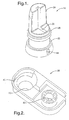
- Each airbag module connection assembly 10 comprises a bushing 14.
- Each bushing 14 is configured for attachment to a locking pin 16 of a base plate 18 of the driver's side airbag module.
- An exemplary bushing is illustrated in Figure 1.
- the bushing has a slot or opening 20 configured for allowing a portion of the locking pin to pass through.
- the bushing also has an upper portion 22 and a lower portion 24.
- the upper portion is generally circular in configuration and is configured to allow movement of the bushing within the airbag module connection assembly as will be discussed herein.
- other equivalent structures or configurations such as oval, elliptical, spherical and equivalents thereof are configured for the upper portion of the bushing.
- Disposed on a portion of the upper portion is a ring of material or protrusion 26. Ring of material 26 depends outwardly from a surface of upper portion 22 and as will be discussed herein provides a means for maintaining a uniform gap between the periphery of the airbag module and its surrounding structure.
- Lower portion 24 and slot 20 are configured to allow a portion of the locking pin to pass therethrough.
- Insulator 28 has a bushing opening 30 and a fastener opening 32.
- Bushing opening 30 is configured to slidably receive bushing 14 therein.
- insulator 28 also has a securement opening 32 configured for receiving a fastening means 34 therein.
- Fastening means 34 provides a means for securing insulator 28 to the steering wheel armature.
- Fastening means 34 can be integral with the steering wheel armature or the insulator or is separately secured to both.
- a locking spring 36 is positioned to engage a slot or opening 38 of the portion of the locking pin, which passes through a slot or opening 20 of bushing 14.
- the locking springs are positioned and configured to be biased into a locking configuration wherein the airbag module is prevented from being completely removed from the steering wheel armature unless the locking spring is urged into a non-locking position wherein the locking spring is no longer engaged in opening 38 of the locking spring, thereby allowing removal of the airbag module from the steering wheel armature.
- the insulator is also configured to have an opening or slot 40 in a sidewall to allow for biasing of the locking spring into the non-engagement position.
- the locking pins are configured to engage a portion of the locking spring, which provides a means for securing the airbag module to the steering wheel armature.
- the bushings are attached to the flat form pins by sliding the bushing onto the locking pin until a protrusion 42 of the locking pin is engaged within an engagement opening 44 of the bushing.
- Each bushing is cylindrical in shape and slotted in the middle. The slot allows the bushing to slide onto and snap-fit to the flat-form locking pin. Essentially, the bushing transforms the flat-sided locking pins into round ones.
- the insulators are located and secured within an opening 46 of a steering wheel armature 48.
- the insulators are secured to the steering wheel armature by an interference fit, mechanical securement or other equivalent means for securing the insulator to the steering wheel armature.
- a biasing spring 50 is disposed between the insulator and a portion of the locking pin or bushing to provide a biasing force in the direction of arrow 52.
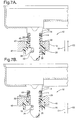
- Opening 30 of the insulator is chamfered or angled to provide a smaller sized opening at a top portion (closer to the driver's side airbag module) and gradually increases to a larger sized opening (further away from the driver's side airbag module).
- the ring of material or protrusion of the bushing makes contact with an inner surface of opening 30. This position is maintained by the biasing force of spring 50 and corresponds to a non-horn activating position.
- the ring of material also provides a means for maintaining a uniform gap between the periphery of the driver's side airbag module and its surrounding structure as will be discussed herein.
- the biasing force of spring 50 is overcome and the module travels in the direction of arrow 54 until contacts or a switch of a horn activation circuit (now shown) or closed and the horn activates (Figure 7B). In this position there is a gap between the sidewalls of opening 30 and protrusion or ring of material 26.
- the driver's side airbag module is capable of movement in the directions between the sidewall of opening 30 and protrusion or ring of material 26.
- spring 50 causes the module to return to the position illustrated in Figure 7 wherein there is no horn activation.
- opening 38 of the locking pin is also configured to allow for movement of the locking spring therein as locking pin 16 moves in the direction of arrow 54.
- the module is free to move in the direction of arrow 54 and returns to its original unbiased configuration which corresponds to a uniform gap between the periphery of the airbag module and its surrounding structure as ring of material 26 and the chamfered wall of insulator 28 guide the module back to its original location every time though the application of the biasing force of spring 50 in the direction of arrow 52.
- the airbag module connection assemblies are contemplated for use with a three pin airbag module (Figure 3) or a two-point attachment ( Figure 4) or with the upper two pins in the cases of a three ( Figure 5) or four-point attachment ( Figure 6).
- the ring of material or protrusion on the bushing enables the airbag module connection assembly to reduce or eliminate gap variations between the airbag module and its surrounding structure.
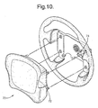
- an airbag module 70 is illustrated having a periphery 72 wherein it is desirable to maintain the periphery in a uniform distance from its surrounding structure 74. Since the bushing slides up and down within the bushing opening of the insulator and the bushing opening is smaller in diameter at the top than at the bottom, the airbag module is precisely positioned in its free state (no horn activation), wherein the bushing stays in the smaller diameter zone of the insulator.
- the diameter of the ring on the bushing is dimensioned slightly smaller than the diameter of this zone of the insulator opening. Hence, in this position, the insulator tightly controls the bushings' movement within the hole. This position corresponds to the position of the driver's side airbag module where uniform gaps are desired.
- a pair of bushings and insulators is employed.
- the bushings, attached to the upper left and right locking pins are exactly the same.
- the insulators, on the other hand, are different.
- One insulator has a round, "net fit” bushing opening 56 ( Figure 9) through which one bushing goes into.
- the second insulator has a "slotted” bushing opening 58 in which the other bushing goes into ( Figure 9).
- the round hole insulator has a dimension corresponding to the free state position that is very close to the dimension of the ring of material disposed on the bushing.
- the round hold insulator will reduce variations in the x as well as y directions.
- the "slotted" hole opening in the left hand insulator will prevent movement in the y direction while being larger in the x direction.
- the left and right hand insulators may be interchanged as long as one opening is round and the other is slotted.
- bushings and insulators are made from polyoxymethylene (Acetyl plastic) or materials having equivalent characteristics.
- the manufacturing methods to produce the bushings there are at least two.
- the first one involves injection molding the bushings as separate parts and then attaching them to the flat-form pins of the driver's side airbag module.
- the bushing is insert molded directly to the flat-form pins ( Figure 8).
Landscapes
- Engineering & Computer Science (AREA)
- Mechanical Engineering (AREA)
- Physics & Mathematics (AREA)
- Acoustics & Sound (AREA)
- Chemical & Material Sciences (AREA)
- Combustion & Propulsion (AREA)
- Transportation (AREA)
- Air Bags (AREA)
- Steering Controls (AREA)
Applications Claiming Priority (4)
| Application Number | Priority Date | Filing Date | Title |
|---|---|---|---|
| US41233202P | 2002-09-20 | 2002-09-20 | |
| US412332P | 2002-09-20 | ||
| US10/373,161 US6874808B2 (en) | 2002-09-20 | 2003-02-24 | Apparatus and method for maintaining a uniform gap between an airbag module and its surrounding structure |
| US373161 | 2003-02-24 |
Publications (3)
| Publication Number | Publication Date |
|---|---|
| EP1400414A2 true EP1400414A2 (fr) | 2004-03-24 |
| EP1400414A3 EP1400414A3 (fr) | 2004-07-14 |
| EP1400414B1 EP1400414B1 (fr) | 2005-12-07 |
Family
ID=31949835
Family Applications (1)
| Application Number | Title | Priority Date | Filing Date |
|---|---|---|---|
| EP03077629A Expired - Lifetime EP1400414B1 (fr) | 2002-09-20 | 2003-08-22 | Dispositif et méthode de maintenir une distance uniforme entre un module d'airbag et sa structure soutenante |
Country Status (5)
| Country | Link |
|---|---|
| US (1) | US6874808B2 (fr) |
| EP (1) | EP1400414B1 (fr) |
| JP (1) | JP2004268899A (fr) |
| KR (1) | KR100539331B1 (fr) |
| DE (1) | DE60302621T2 (fr) |
Cited By (5)
| Publication number | Priority date | Publication date | Assignee | Title |
|---|---|---|---|---|
| EP1702813A1 (fr) * | 2005-03-16 | 2006-09-20 | Takata Corporation | Volant avec dispositif d'airbag |
| EP2195200A4 (fr) * | 2007-10-02 | 2012-10-24 | Autoliv Asp Inc | Ensemble de module de coussin de sécurité gonflable pour contrôler l'espace adjacent à la protection de coussin de sécurité gonflable |
| CN110431050A (zh) * | 2017-03-10 | 2019-11-08 | 芦森工业株式会社 | 转向盘结构 |
| EP3812240A4 (fr) * | 2018-06-25 | 2022-03-16 | Autoliv Development AB | Structure pour monter et fixer une unité d'amortisseur dans une roue de direction, et roue de direction |
| US11285901B2 (en) * | 2019-11-18 | 2022-03-29 | Joyson Safety Systems Japan K.K. | Steering wheel |
Families Citing this family (23)
| Publication number | Priority date | Publication date | Assignee | Title |
|---|---|---|---|---|
| US7185915B2 (en) * | 2003-02-27 | 2007-03-06 | Toyoda Gosei Co., Ltd. | Steering wheel incorporating air bag device |
| US7059631B2 (en) * | 2003-04-29 | 2006-06-13 | Toyoda Gosei Co., Ltd. | Method and apparatus for coupling a driver's side airbag to a steering wheel |
| US20040239080A1 (en) * | 2003-05-30 | 2004-12-02 | Berrahou Philip F. | Housing retention mechanism |
| US7533897B1 (en) * | 2005-02-16 | 2009-05-19 | Key Safety Systems, Inc. | Method and apparatus for securing an air bag |
| US7464959B2 (en) * | 2005-03-01 | 2008-12-16 | Trw Vehicle Safety Systems Inc. | Apparatus having a mechanism for limiting the movement of an air bag module relative to a steering wheel |
| KR100657662B1 (ko) * | 2005-10-06 | 2006-12-14 | 기아자동차주식회사 | 차량의 운전석 에어백 모듈 조립장치 |
| US20100219621A1 (en) * | 2009-02-27 | 2010-09-02 | Toyoda Gosei Co., Ltd. | Airbag-equipped steering wheel device |
| KR101024110B1 (ko) | 2009-08-10 | 2011-03-22 | (주)에이패스 | 스티어링휠용 휠커버 조립방법 |
| JP5797882B2 (ja) * | 2009-12-22 | 2015-10-21 | 日本プラスト株式会社 | 自動車用ステアリングホイール |
| JP5508149B2 (ja) * | 2010-06-08 | 2014-05-28 | 日本プラスト株式会社 | 自動車用ステアリングホイール |
| JP5206756B2 (ja) * | 2010-09-30 | 2013-06-12 | 豊田合成株式会社 | エアバッグ装置付きステアリングホイール |
| CN105980233B (zh) * | 2014-02-21 | 2017-11-17 | 本田技研工业株式会社 | 方向盘结构 |
| GB2540254B (en) * | 2014-03-18 | 2018-02-28 | Nihon Plast Co Ltd | Steering wheel |
| KR102293578B1 (ko) * | 2015-07-22 | 2021-08-25 | 현대모비스 주식회사 | 조향휠 에어백 장치 |
| DE102016005020B4 (de) * | 2016-04-26 | 2019-08-14 | Dalphi Metal Espana, S.A. | Gassackeinheit und Fahrzeuginsassensicherheitssystem mit einer solchen Gassackeinheit sowie Herstellungsverfahren |
| US9828052B2 (en) | 2016-04-29 | 2017-11-28 | Honda Motor Co., Ltd. | Systems and methods for use in testing the installation of an airbag module in a vehicle |
| DE102016124530A1 (de) * | 2016-12-15 | 2018-06-21 | Trw Automotive Safety Systems Gmbh | Kopplungsvorrichtung zur schwingfähigen Befestigung eines Gassackmoduls an einem Fahrzeuglenkrad |
| US11718257B2 (en) * | 2016-12-15 | 2023-08-08 | Zf Passive Safety Systems Us Inc | Coupling device for mounting an airbag module to be oscillating on a vehicle steering wheel |
| JP7015194B2 (ja) | 2018-03-19 | 2022-02-02 | 芦森工業株式会社 | ステアリングホイール |
| US10926698B2 (en) * | 2018-12-17 | 2021-02-23 | Key Safety Systems, Inc. | Integrated steering wheel, vibration absorber, and driver airbag |
| KR102693552B1 (ko) * | 2019-04-11 | 2024-08-08 | 현대모비스 주식회사 | 운전석 에어백장치 |
| CN111994032B (zh) * | 2020-07-10 | 2025-12-12 | 上海东方久乐汽车安全气囊有限公司 | 一种定位套、定位配合结构及汽车方向盘组件 |
| KR20240033489A (ko) * | 2022-09-05 | 2024-03-12 | 현대자동차주식회사 | 스티어링휠과, 그 스티어링휠의 댐퍼유닛 |
Family Cites Families (12)
| Publication number | Priority date | Publication date | Assignee | Title |
|---|---|---|---|---|
| US5333897A (en) * | 1993-10-25 | 1994-08-02 | General Motors Corporation | Snap lock pin inflatable restraint module mounting mechanism |
| US5380037A (en) * | 1993-10-25 | 1995-01-10 | General Motors Corporation | Snap-in inflatable restraint module mounting mechanism including latch elements |
| US5630611A (en) * | 1995-07-21 | 1997-05-20 | Textron Inc. | Mounting assembly for air bag |
| US5639113A (en) * | 1995-07-21 | 1997-06-17 | Textron Inc. | Mounting assembly for air bag |
| DE19724029A1 (de) * | 1997-06-06 | 1998-12-24 | Takata Europ Gmbh | Airbag-Vorrichtung |
| US6092832A (en) * | 1998-03-04 | 2000-07-25 | General Motors Corporation | Air bag module mounting mechanism and method of making |
| US6148470A (en) * | 1998-08-14 | 2000-11-21 | Valeo Electrical Systems, Inc. | Windshield wiping system |
| US6237944B1 (en) * | 1999-09-30 | 2001-05-29 | Delphi Technologies, Inc. | Mounting mechanism for inflatable restraint system |
| US6325408B1 (en) * | 2000-05-15 | 2001-12-04 | Breed Automotive Technology, Inc. | Air bag attachment arrangement |
| EP1418095B1 (fr) * | 2000-06-27 | 2006-04-26 | Toyoda Gosei Co., Ltd. | Volant avec sac gonflable |
| DE10156424B4 (de) * | 2000-11-27 | 2016-11-24 | Autoliv Development Ab | Luftsackmodul für Kraftfahrzeuge |
| US6454300B1 (en) | 2001-02-27 | 2002-09-24 | Delphi Technologies, Inc. | Air bag tether release assembly |
-
2003
- 2003-02-24 US US10/373,161 patent/US6874808B2/en not_active Expired - Fee Related
- 2003-08-22 DE DE60302621T patent/DE60302621T2/de not_active Expired - Lifetime
- 2003-08-22 EP EP03077629A patent/EP1400414B1/fr not_active Expired - Lifetime
- 2003-09-19 JP JP2003327132A patent/JP2004268899A/ja active Pending
- 2003-09-19 KR KR10-2003-0065117A patent/KR100539331B1/ko not_active Expired - Fee Related
Cited By (7)
| Publication number | Priority date | Publication date | Assignee | Title |
|---|---|---|---|---|
| EP1702813A1 (fr) * | 2005-03-16 | 2006-09-20 | Takata Corporation | Volant avec dispositif d'airbag |
| US7566071B2 (en) | 2005-03-16 | 2009-07-28 | Takata Corporation | Steering wheel with airbag apparatus |
| EP2195200A4 (fr) * | 2007-10-02 | 2012-10-24 | Autoliv Asp Inc | Ensemble de module de coussin de sécurité gonflable pour contrôler l'espace adjacent à la protection de coussin de sécurité gonflable |
| CN110431050A (zh) * | 2017-03-10 | 2019-11-08 | 芦森工业株式会社 | 转向盘结构 |
| CN110431050B (zh) * | 2017-03-10 | 2022-03-25 | 芦森工业株式会社 | 转向盘结构 |
| EP3812240A4 (fr) * | 2018-06-25 | 2022-03-16 | Autoliv Development AB | Structure pour monter et fixer une unité d'amortisseur dans une roue de direction, et roue de direction |
| US11285901B2 (en) * | 2019-11-18 | 2022-03-29 | Joyson Safety Systems Japan K.K. | Steering wheel |
Also Published As
| Publication number | Publication date |
|---|---|
| JP2004268899A (ja) | 2004-09-30 |
| DE60302621D1 (de) | 2006-01-12 |
| US20040056453A1 (en) | 2004-03-25 |
| EP1400414A3 (fr) | 2004-07-14 |
| EP1400414B1 (fr) | 2005-12-07 |
| KR20040025859A (ko) | 2004-03-26 |
| US6874808B2 (en) | 2005-04-05 |
| KR100539331B1 (ko) | 2005-12-28 |
| DE60302621T2 (de) | 2006-06-29 |
Similar Documents
| Publication | Publication Date | Title |
|---|---|---|
| EP1400414B1 (fr) | Dispositif et méthode de maintenir une distance uniforme entre un module d'airbag et sa structure soutenante | |
| US5333897A (en) | Snap lock pin inflatable restraint module mounting mechanism | |
| US5380037A (en) | Snap-in inflatable restraint module mounting mechanism including latch elements | |
| US6840537B2 (en) | Airbag module attachment arrangement | |
| US10196028B2 (en) | Steering wheel | |
| US20040178611A1 (en) | Driver airbag formed contact spring | |
| US7387312B2 (en) | Steering apparatus | |
| JPH04353072A (ja) | ステアリングホイールのホーンスイッチ装置 | |
| US5950494A (en) | Steering wheel | |
| KR100519231B1 (ko) | 차량의 혼 스위치 어셈블리 | |
| US20050230943A1 (en) | Vehicle air bag module retention system | |
| US7055854B2 (en) | Snap-in castanet airbag module for a vehicular steering wheel | |
| JP3726101B2 (ja) | 運転席用エアバッグモジュール | |
| JP2000085587A (ja) | ステアリングホイールおよびステアリングホイールの製造方法 | |
| US7422236B2 (en) | Apparatus and method for providing a horn contact mechanism | |
| JP6695724B2 (ja) | ハンドル | |
| JP4029583B2 (ja) | ステアリングホイール | |
| JP7363849B2 (ja) | ステアリングホイール | |
| JP3822712B2 (ja) | ステアリングホイール | |
| JP3665881B2 (ja) | 運転席用エアバッグモジュール | |
| JP2589244Y2 (ja) | 金型装置 | |
| JPH08253155A (ja) | ステアリングホイール | |
| JPH061246A (ja) | ステアリングホイール | |
| JP2006205890A (ja) | ステアリングホイール | |
| JPH07291136A (ja) | ステアリングホイール |
Legal Events
| Date | Code | Title | Description |
|---|---|---|---|
| PUAI | Public reference made under article 153(3) epc to a published international application that has entered the european phase |
Free format text: ORIGINAL CODE: 0009012 |
|
| AK | Designated contracting states |
Kind code of ref document: A2 Designated state(s): AT BE BG CH CY CZ DE DK EE ES FI FR GB GR HU IE IT LI LU MC NL PT RO SE SI SK TR |
|
| AX | Request for extension of the european patent |
Extension state: AL LT LV MK |
|
| PUAL | Search report despatched |
Free format text: ORIGINAL CODE: 0009013 |
|
| AK | Designated contracting states |
Kind code of ref document: A3 Designated state(s): AT BE BG CH CY CZ DE DK EE ES FI FR GB GR HU IE IT LI LU MC NL PT RO SE SI SK TR |
|
| AX | Request for extension of the european patent |
Extension state: AL LT LV MK |
|
| 17P | Request for examination filed |
Effective date: 20050114 |
|
| AKX | Designation fees paid |
Designated state(s): DE FR GB |
|
| GRAP | Despatch of communication of intention to grant a patent |
Free format text: ORIGINAL CODE: EPIDOSNIGR1 |
|
| GRAS | Grant fee paid |
Free format text: ORIGINAL CODE: EPIDOSNIGR3 |
|
| GRAA | (expected) grant |
Free format text: ORIGINAL CODE: 0009210 |
|
| AK | Designated contracting states |
Kind code of ref document: B1 Designated state(s): DE FR GB |
|
| REG | Reference to a national code |
Ref country code: GB Ref legal event code: FG4D |
|
| REF | Corresponds to: |
Ref document number: 60302621 Country of ref document: DE Date of ref document: 20060112 Kind code of ref document: P |
|
| PLBE | No opposition filed within time limit |
Free format text: ORIGINAL CODE: 0009261 |
|
| STAA | Information on the status of an ep patent application or granted ep patent |
Free format text: STATUS: NO OPPOSITION FILED WITHIN TIME LIMIT |
|
| 26N | No opposition filed |
Effective date: 20060908 |
|
| EN | Fr: translation not filed | ||
| PG25 | Lapsed in a contracting state [announced via postgrant information from national office to epo] |
Ref country code: FR Free format text: LAPSE BECAUSE OF FAILURE TO SUBMIT A TRANSLATION OF THE DESCRIPTION OR TO PAY THE FEE WITHIN THE PRESCRIBED TIME-LIMIT Effective date: 20070126 |
|
| GBPC | Gb: european patent ceased through non-payment of renewal fee |
Effective date: 20070822 |
|
| PG25 | Lapsed in a contracting state [announced via postgrant information from national office to epo] |
Ref country code: GB Free format text: LAPSE BECAUSE OF NON-PAYMENT OF DUE FEES Effective date: 20070822 Ref country code: FR Free format text: LAPSE BECAUSE OF FAILURE TO SUBMIT A TRANSLATION OF THE DESCRIPTION OR TO PAY THE FEE WITHIN THE PRESCRIBED TIME-LIMIT Effective date: 20051207 |
|
| REG | Reference to a national code |
Ref country code: DE Ref legal event code: R081 Ref document number: 60302621 Country of ref document: DE Owner name: AUTOLIV DEVELOPMENT AB, SE Free format text: FORMER OWNER: DELPHI TECHNOLOGIES, INC., TROY, US Effective date: 20110414 |
|
| PGFP | Annual fee paid to national office [announced via postgrant information from national office to epo] |
Ref country code: DE Payment date: 20110628 Year of fee payment: 9 |
|
| PG25 | Lapsed in a contracting state [announced via postgrant information from national office to epo] |
Ref country code: DE Free format text: LAPSE BECAUSE OF NON-PAYMENT OF DUE FEES Effective date: 20130301 |
|
| REG | Reference to a national code |
Ref country code: DE Ref legal event code: R119 Ref document number: 60302621 Country of ref document: DE Effective date: 20130301 |