EP1400634B1 - Verriegelungselement für einen Gitterrost auf einer Entwässerungsrinne und Werkzeug zum Entfernen desselben - Google Patents
Verriegelungselement für einen Gitterrost auf einer Entwässerungsrinne und Werkzeug zum Entfernen desselben Download PDFInfo
- Publication number
- EP1400634B1 EP1400634B1 EP03291842A EP03291842A EP1400634B1 EP 1400634 B1 EP1400634 B1 EP 1400634B1 EP 03291842 A EP03291842 A EP 03291842A EP 03291842 A EP03291842 A EP 03291842A EP 1400634 B1 EP1400634 B1 EP 1400634B1
- Authority
- EP
- European Patent Office
- Prior art keywords
- grating
- gutter
- section
- clip
- clips
- Prior art date
- Legal status (The legal status is an assumption and is not a legal conclusion. Google has not performed a legal analysis and makes no representation as to the accuracy of the status listed.)
- Expired - Lifetime
Links
- 238000004873 anchoring Methods 0.000 claims abstract description 21
- 239000000463 material Substances 0.000 claims abstract description 11
- 239000002184 metal Substances 0.000 claims description 7
- 239000007787 solid Substances 0.000 claims description 4
- 230000014759 maintenance of location Effects 0.000 claims description 3
- 238000003754 machining Methods 0.000 claims description 2
- 238000005452 bending Methods 0.000 claims 1
- 230000003100 immobilizing effect Effects 0.000 claims 1
- 230000037431 insertion Effects 0.000 claims 1
- 238000003780 insertion Methods 0.000 claims 1
- 238000007493 shaping process Methods 0.000 claims 1
- 239000004567 concrete Substances 0.000 description 3
- 238000005266 casting Methods 0.000 description 2
- 238000012423 maintenance Methods 0.000 description 2
- 239000004568 cement Substances 0.000 description 1
- 230000000295 complement effect Effects 0.000 description 1
- 238000005553 drilling Methods 0.000 description 1
- 230000000694 effects Effects 0.000 description 1
- 238000000605 extraction Methods 0.000 description 1
- JEIPFZHSYJVQDO-UHFFFAOYSA-N iron(III) oxide Inorganic materials O=[Fe]O[Fe]=O JEIPFZHSYJVQDO-UHFFFAOYSA-N 0.000 description 1
- 238000002955 isolation Methods 0.000 description 1
- 239000007769 metal material Substances 0.000 description 1
- 238000004080 punching Methods 0.000 description 1
- 239000011150 reinforced concrete Substances 0.000 description 1
- 230000003252 repetitive effect Effects 0.000 description 1
- 239000011347 resin Substances 0.000 description 1
- 229920005989 resin Polymers 0.000 description 1
- 230000000284 resting effect Effects 0.000 description 1
- 238000000926 separation method Methods 0.000 description 1
- 239000002351 wastewater Substances 0.000 description 1
Images






Classifications
-
- E—FIXED CONSTRUCTIONS
- E03—WATER SUPPLY; SEWERAGE
- E03F—SEWERS; CESSPOOLS
- E03F5/00—Sewerage structures
- E03F5/04—Gullies inlets, road sinks, floor drains with or without odour seals or sediment traps
- E03F5/06—Gully gratings
-
- E—FIXED CONSTRUCTIONS
- E03—WATER SUPPLY; SEWERAGE
- E03F—SEWERS; CESSPOOLS
- E03F5/00—Sewerage structures
- E03F5/04—Gullies inlets, road sinks, floor drains with or without odour seals or sediment traps
- E03F5/06—Gully gratings
- E03F2005/065—Gully gratings with elastic locking elements
Definitions
- the present invention generally relates to a closure element of a receptacle, and more particularly to a grid intended to be removably attached to a collection gutter of waste water, rainwater, etc ..., while allowing the passage of vehicles without hindrance.
- Such channels are generally made of reinforced concrete, self-leveled concrete, resin and consist of successive monoblock elements, generally "U” shaped and receiving on the upper profiled edges of the vertical side walls, one or more grids in series, these edges being themselves covered with a metal section covering the upper ends of the side walls of the channel to define an "L” rebate intended to cooperate in closure with the longitudinal edges of said grid.
- a prior solution to this problem consists in proposing a fixing of the grid by means of screws passing through holes of the latter to be screwed into threaded housings of the upper edge of the gutter in which were introduced during the casting of threaded hollow inserts.
- fastening means also known, consist of at least two resilient arms, integral with the grid, and each having at their free ends, lugs intended to cooperate with recesses of the gutter, these arms and lugs having a shape such that their cooperation with the recesses of the gutter produce an elastic effect in the vertical and horizontal direction, so as to ensure the maintenance of the grid.
- the present invention aims to remedy all of these disadvantages and relates for this purpose a device for connecting a closure member on a receptacle, in particular a gate on a gutter, which consists of monobloc elements successive, generally "U” shaped whose lateral wings are capped at their upper ends of metal profiles defining an "L” rabbet intended to cooperate in closing with the longitudinal edges of said grid and immobilize through resiliently deformable fastening means adapted to make said removable grid, characterized in that each of the metal profiles comprises on the one hand at its lower part anchoring means in the flanges of the gutter made in perpendicular extension towards the bottom of the branch horizontal "A" of the "L” constituting the profile and secondly at its upper part of the anchoring means of a at least one fastening clip of the grid made by removal of material on the vertical leg "B" of the "L” constituting the profile, said means for anchoring the profile in the channel as well as said means for anchoring the clip in the profile being obtained therewith to constitute
- such a device allows the automatic attachment of the profile in the material of the gutter, usually concrete, without the need for intervention.
- This system is simple by its implementation in the mold and effective since ensuring the maintenance of the profile on the gutter for normal use.
- the interest of the invention lies in the shape of the profile.
- the profile becomes integral with the channel while having means for anchoring the clips on the visible portion of said profile.
- Another advantage of the invention consists in the fact that the setting of the grid can be carried out simply and without tools in a fast and safe manner.
- the present invention also relates to the features which will emerge during the following description, which should be considered in isolation or in all their possible technical combinations.
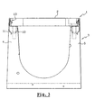
- the device 1 designated globally on the Figures 1 to 7 is intended for the connection, according to the present nonlimiting exemplary embodiment, of a grid 2 on a gutter 3.
- This rabbet is intended to cooperate in closing with the longitudinal edges 8 and 9 of said grid 2 and to immobilize it by means of elastically deformable fixing means able to make said grid 2 removable from the channel 3.
- each of the metal profiles 6, 7 comprises on the one hand at its lower part means 10, 11 for anchoring in the flanges 4, 5 of the gutter 3 made perpendicularly to the bottom of the horizontal branch " A “of the” L “constituting the profile 6 or 7 and secondly at its upper part means 12 for anchoring at least one fastening clip 13 of the grid 2 made by removal of material on the vertical branch" B “of the” L “constituting the profile 6 or 7, said anchoring means 10, 11 of the profile 6 or 7 in the channel 3 as well as said anchoring means 12 of the clip 13 in the profile 6 or 7 being obtained with this one to constitute a monoblock element. (see Figures 8, 9 and 10 ).
- the anchoring means 10, 11 of the profile in the flanges 3, 4 of the gutter 3 are constituted by a series of downwardly directed legs coming from each of the longitudinal edges of the horizontal leg "A" of the "L” forming said profile, the tabs 10 of one of the edges being made shifted with a series of lugs 11 of the other edge. This is particularly visible on the figure 10 .
- each series of lugs 10, 11 is made in the extension of a solid zone 14, 15 constituting their base, in the perpendicular downward extension of the horizontal leg "A" of the "L” constituting the profile 5 or 6 .
- the set of tabs 10, 11 of each of the longitudinal edges are curved with respect to the solid zone 14, 15, to form an angle so that they are directed towards each other towards the inside. of each of the wings 4, 5 of the gutter 3.
- each of the anchoring lugs 10, 11 of each series forms a hook 16, 17 directed outwardly of the flanges of the channel while remaining contained therein.
- legs 10 and 11 are of different heights.
- the profile 6, 7 is obtained integrally from a rectangular sheet blank in which are produced by cutting or punching the two series of tabs 10, 11 and the lights 12 for the 13, as well as by drilling a series of circular holes 18 for centering pins of the grid 2 or complementary fixing screws thereof, said section 6, 7 being, successively machining operations, consistent by folding and against folding.
- these are made from a sheet of an elastically deformable material, shaped thereafter.
- each of the clips 13 has a vertical leg 19 against bent at its upper part 20 to form a foot, of dimensions and shapes such as to be introduced into the quadrangular lights 12 of the section 6 or 7 which are intended for them and come resting behind the vertical leg "B" thereof, the vertical retention of the clip 13 being provided by a support of the part against bent 20 against the lower edge of the light 12 and a bearing of support an upper portion 21 of the clip 13 against the upper edge of said slot 12 after assembly, said upper part 21 being constituted by two branches 22, 23 forming an elastic pin one of which 22 extends the horizontal part 20 of the foot and the other 23 free and inclined is the latching means itself on the grid 2 of the channel 3.
- the grid 2 of the channel 3 comprises on its upper face a plurality of reservation 24 in number equal to that of the clips 13 to allow the housing thereof for the vertical and longitudinal retention of said grid 2.
- the end of the free branch 23 of the clip 13 is bent inwardly to allow its sliding on a lower edge of the corresponding reservation 24 of the grid 2.
- Said flange has a recess 26 to form an angle with a vertical wall 27 of the reservation, greater than 90 ° to make it easier to remove the grid 2 after retraction of said free branch 23 of the clip 13.
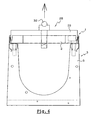
- the invention also relates to a tool 28 for dismounting and transporting a grid 2 attached to a channel 3 via the connecting device described above.
- This tool 28 is constituted by a bridge 29 formed by a horizontal crossbar and two vertical end feet 30, 31, intended to be inserted in two opposite reservations 24 of the grid 2 between their vertical walls 27 and the free branches 23 clips 13 in place, in order to push them towards their disengagement of the reservations 24.
- the extraction of the grid 2 of the channel 3 is performed using a rotary handle 32 through the bridge 29 from its upper face via an axis rotary 33 whose lower end comprises two arms 34, 35 extending freely on either side of the axis 33.
- these arms 34, 35 and their distance relative to the underside of the bridge 29 are such that they allow said arms 34, 35 to be introduced between two bars of the grid 2 from above and then turned at an angle of about 90 ° under said bars in order to be able to exert traction on them and consequently raise the grid 2.
- the free ends of the vertical legs 30, 31 of the bridge 29 each have a chamfer 36 directed inwards to facilitate their introduction between the clip 13 of the profile 6 or 7 and the reservation 24 from the grid 2.
- the ends of the arms 34, 35 have chamfers 37 made on two diagonally opposite upper angles in order to facilitate their passage under the bars of the grid 2 in view of its lifting.
- the clip 13 placed in the profile 6 or 7 of the channel 3 deforms during the introduction of the grid 2.
- the clip 13 resumes its original position thereby retaining the grid 2.
- the device is then secure, the effort required to unlock the gate 2 being greater than that exerted by grid 2 in its intended use.
- This lock also allows disassembly of the grid, if necessary, as already mentioned.
- the clip 13 is fixed to the channel 3 being blocked, removably if necessary, in the section 6, 7 thanks to its shape, but is in no way attached to the grid 2.
- the clip 13 is placed on the profile before casting the channel 3 so as to prevent the cement is housed between the walls of the profile and more particularly in the area of the light 12 in which must be inserted the tab 19 clip 13.
Landscapes
- Life Sciences & Earth Sciences (AREA)
- Engineering & Computer Science (AREA)
- Hydrology & Water Resources (AREA)
- Public Health (AREA)
- Water Supply & Treatment (AREA)
- Health & Medical Sciences (AREA)
- Supports For Pipes And Cables (AREA)
- Sewage (AREA)
- Discharging, Photosensitive Material Shape In Electrophotography (AREA)
- Image-Pickup Tubes, Image-Amplification Tubes, And Storage Tubes (AREA)
- Soil Working Implements (AREA)
- Baking, Grill, Roasting (AREA)
- Sink And Installation For Waste Water (AREA)
- Bathtub Accessories (AREA)
- Connection Of Plates (AREA)
Claims (14)
- Vorrichtung zum Verbinden eines Schließteils an einen Behälter, insbesondere eines Gitters an einer Rinne oder Abflußrinne (3), welche Verbindungsvorrichtung aus mehreren aneinander angeordneten, einstückigen Bauteilen gebildet ist und im allgemeinen eine U-Form aufweist, deren Seitenschenkel an deren oberen Enden mit metallischen Profilen (6 und 7) bedeckt sind, die L-förmige Falze definieren, die dazu ausgelegt sind, mit den Längsrändern (8 und 9) des Gitters (2) schließend zusammenzuwirken und es unbeweglich zu machen, wobei jeder Falz einerseits an dessen unteren Teil eine Einrichtung zum Verankern in den Schenkeln (4, 5) der Rinne (3) und andererseits an dessen oberen Teil eine elastisch verformbare Befestigungseinrichtung umfaßt, die das Gitter (2) beweglich macht, dadurch gekennzeichnet, daß die Befestigungseinrichtung durch wenigstens eine elastisch verformbare Klemme (13) und durch eine Einrichtung zum Verankern dieser gebildet ist, welche durch Materialbeseitigung an dem vertikalen Arm "B" der das Profile (6 oder 7) bildenden L-Form, wobei die Einrichtung zum Verankern des Profils (6 oder 7) in der Rinne (3) sowie die Einrichtung (12) zum Verankern der Klemme (13) in dem Profil (6 oder 7) dadurch erhalten sind, um ein einstückiges Bauteil zu bilden.
- Vorrichtung nach Anspruch 1, dadurch gekennzeichnet, daß die Einrichtung zum Verankern des Profils in den Schenkeln (3, 4) der Rinne (3) durch eine Reihe von Klauen oder Haken gebildet ist, die nach unten ausgerichtet sind und aus jedem der Längsränder des horizontalen Arms "A" der das Profil bildenden L-Form entstanden sind, wobei die Klauen eines Rands so realisiert sind, daß sie mit einer Reihe von Klauen (11) des anderen Rands verschoben werden
- Vorrichtung nach Anspruch 2, dadurch gekennzeichnet, daß jede Reihe Klauen (10, 11) in der Verlängerung eines freien Bereichs (14, 15), der deren Basis bildet, nämlich in der Verlängerung senkrecht nach unten von dem horizontalen Arm "A", der das Profil (5 oder 6) bildenden L-Form.
- Vorrichtung nach Anspruch 3, dadurch gekennzeichnet, daß die Anordnung der Klauen (10, 11) jedes Längsrands relativ zu dem freien Bereich (14, 15) gebogen ist, um derart einen Winkel zu bilden, daß sie untereinander in Richtung der Innenseite jedes Schenkels (4, 5) der Rinne ausgerichtet sind.
- Vorrichtung nach Anspruch 4, dadurch gekennzeichnet, daß die Enden jeder Klaue (10, 11) zum Greifen jeder Reihe einen Haken (16, 17) bildet, der hin zur Außenseite der Schenkel der Rinne gerichtet ist, wobei alles in diesen enthalten bleibt.
- Vorrichtung nach Anspruch 1, dadurch gekennzeichnet, daß die Einrichtung zum Verankern der Klemmen (13) in den vertikalen Arm "B" der das Profil bildenden L-Form durch quadratische Öffnungen gebildet ist, die in den vertikalen Arm "B" münden.
- Vorrichtung nach einem der Ansprüche 5 bis 6, dadurch gekennzeichnet, daß das Profil (6, 7) aus einem Stück ausgehend von einer rechteckigen Blechplatte realisiert ist, in der die beiden Reihen von Klauen (10, 11) und die Öffnungen (12) für die Klemmen (13) sowie eine Reihe von kreisförmigen Löchern (18) für Zentrierstifte des Gitters (2) oder für Befestigungsschrauben ausgebildet sind, die formkomplementär zu den Löchern gebildet sind, wobei das Profil (6, 7) nach einer spanabhebenden Bearbeitung durch Falzen und Gegenfalzen geformt sind.
- Vorrichtung nach einem der Ansprüche 1 bis 7, dadurch gekennzeichnet, daß jede Klemme (13) ausgehend von einem Blatt aus einem elastisch verformbaren Material gebildet ist.
- Vorrichtung nach Anspruch 8, dadurch gekennzeichnet, daß jede Klemme (13) einen vertikalen Arm (19) aufweist, der an dessen oberen Teil (20) umgebogen ist, um einen Fuß mit Abmessungen und solchen Formen zu bilden, damit er in die quadratischen Öffnungen des Profils (6 oder 7) einbringbar ist, die für diese bestimmt sind und hinter vertikalen Arm "B" von diesem in Abstützung kommt, wobei nach der Montage der vertikale Rückhalt der Klemme (13) durch eine Abstützung des umgebogenen Teils gegen den Innenrand der Öffnung (12) und durch eine Abstützung eines oberen Teils (21) der Klemme (13) gegen den oberen Rand der Öffnung (12) sichergestellt ist, wobei der obere Teil (21) durch zwei Arme (20, 23) gebildet ist, die eine elastische Nadel bilden, von denen die eine den horizontalen Teil (20) des Fußes verlängert und die andere (23) frei und geneigt die Einrichtung zum Klemmen an dem Gitter (2) der Rinne (3) bildet.
- Vorrichtung nach einem der Ansprüche 1 bis 9, dadurch gekennzeichnet, daß das Gitter der Rinne (3) auf deren Oberseite mehrere Aufnahmen (24) in der gleichen Zahl wie Klemmen (13) umfaßt, um das Unterbringen dieser im Hinblick auf die vertikale Halterung sowie auch der longitudinalen Halterung des Gitters (2) zuzulassen.
- Vorrichtung nach Anspruch 9 und 10, dadurch gekennzeichnet, daß das Ende des freien Arms (23) der Klemme (13) hin zur Innenseite umgebogen ist, um dessen Gleiten an einem unteren Rand der Aufnahme (24), die dem Gitter (2) entspricht, zuzulassen, und daß der Rand einen Balg (26) aufweist, um einen Winkel mit einer vertikalen Wand (27) der Aufnahme zu bilden, der größer als 90° ist, um das Ablegen des Gitters (2) nach Senken der freien Arme (23) der Klemme (13) zu erleichtern.
- Werkzeug (28) zum Demontieren oder zum Transport eines Gitters (2), das an einer Rinne (3) mit Hilfe einer nach einem der Ansprüche 1 bis 11 ausgebildeten Vorrichtung befestigt ist, dadurch gekennzeichnet, daß das Werkzeug durch eine Brücke (29) gebildet ist, die aus einer horizontalen Traverse und zwei vertikalen Endfüßen (30, 31) gebildet ist, die in zwei gegenüberliegenden Aufnahmen (24) des Gitters (2) zwischen deren vertikalen Wänden (27) und den freien Armen (23) der Klemmen (13) an Ort und Stelle eingesetzt werden sollen, um diese für deren Befreiung aus den Aufnahmen (24) zurückzudrängen, wobei das Abnehmen des Gitters (2) von der Rinne (3) mit Hilfe eines drehbaren Griffs (32) bewerkstelligt wird, der sich durch die Brücke (29) ausgehend von einer oberen Seite mit Hilfe einer Welle (33) durchquert, deren unteres Ende zwei Arme (34, 35) umfaßt, die sich frei einerseits und andererseits der Welle (33) erstrecken, wobei die Abmessungen dieser Arme (34, 35) und ihr Abstand zur Unterseite der Brücke (29) derart sind, daß sie es den Armen (34, 35) ermöglichen, zwischen zwei Gitterstäben des Gitters (2) von unten eingebracht zu werden und anschließend um einen Winkel um etwa 90° unter den Gitterstäben gedreht zu werden, um eine Zugkraft an diesen auszuüben und folglich das Gitter (2) anzuheben.
- Werkzeug (28) nach Anspruch 12, dadurch gekennzeichnet, daß die freien Enden der vertikalen Füße (31, 32) der Brücke (29) jeweils eine Seitenfase (36) aufweisen, die ins Innere gerichtet ist, um das Einbringen zwischen der Klemme (13) des Profils (6 oder 7) und der Aufnahme (24) des Gitters (2) zu erleichtern.
- Werkzeug (28) nach einem der Ansprüche (12 und 13), dadurch gekennzeichnet, daß die Enden der Arme (34, 35) Seitenfasen (37) aufweisen, die an zwei oberen Winkeln realisiert sind, die sich diagonal gegenüberliegen, um deren Durchgang unter den Gitterstäben des Gitters (2) im Hinblick auf deren Anhebung zu erleichtern.
Applications Claiming Priority (2)
| Application Number | Priority Date | Filing Date | Title |
|---|---|---|---|
| FR0211742 | 2002-09-19 | ||
| FR0211742A FR2844814B1 (fr) | 2002-09-19 | 2002-09-19 | Dispositif de liaison d'une grille sur un caniveau et outil de demontage correspondant |
Publications (2)
| Publication Number | Publication Date |
|---|---|
| EP1400634A1 EP1400634A1 (de) | 2004-03-24 |
| EP1400634B1 true EP1400634B1 (de) | 2008-02-27 |
Family
ID=31897522
Family Applications (1)
| Application Number | Title | Priority Date | Filing Date |
|---|---|---|---|
| EP03291842A Expired - Lifetime EP1400634B1 (de) | 2002-09-19 | 2003-07-25 | Verriegelungselement für einen Gitterrost auf einer Entwässerungsrinne und Werkzeug zum Entfernen desselben |
Country Status (5)
| Country | Link |
|---|---|
| EP (1) | EP1400634B1 (de) |
| AT (1) | ATE387547T1 (de) |
| DE (1) | DE60319315T2 (de) |
| ES (1) | ES2300550T3 (de) |
| FR (1) | FR2844814B1 (de) |
Families Citing this family (2)
| Publication number | Priority date | Publication date | Assignee | Title |
|---|---|---|---|---|
| RU2576268C1 (ru) * | 2015-01-26 | 2016-02-27 | Общество с ограниченной ответственностью "КапиталФорм" | Решетка дождеприемного канала |
| CN115180422B (zh) * | 2022-08-10 | 2023-09-12 | 北京达博有色金属焊料有限责任公司 | 一种叠套包装盒拆分机构及自动投料设备 |
Family Cites Families (4)
| Publication number | Priority date | Publication date | Assignee | Title |
|---|---|---|---|---|
| DE19511788C9 (de) * | 1995-03-30 | 2005-05-25 | Mea Meisinger Stahl Und Kunststoff Gmbh | Lösbare Verriegelungsvorrichtung für einen befahrbaren Rost einer Entwässerungsrinne |
| EP0761885A1 (de) * | 1995-09-08 | 1997-03-12 | Poly-Bauelemente AG | Vorrichtung zum Sichern einer Rinnenabdeckung auf einer Entwässerungsrinne |
| DE29808197U1 (de) * | 1998-05-07 | 1998-08-20 | Hauraton Betonwarenfabrik GmbH & Co KG, 76437 Rastatt | Entwässerungsrinne |
| DE20010316U1 (de) * | 2000-06-08 | 2001-10-18 | Broermann, Rita, 59609 Anröchte | Rinnenelement |
-
2002
- 2002-09-19 FR FR0211742A patent/FR2844814B1/fr not_active Expired - Lifetime
-
2003
- 2003-07-25 EP EP03291842A patent/EP1400634B1/de not_active Expired - Lifetime
- 2003-07-25 DE DE60319315T patent/DE60319315T2/de not_active Expired - Lifetime
- 2003-07-25 ES ES03291842T patent/ES2300550T3/es not_active Expired - Lifetime
- 2003-07-25 AT AT03291842T patent/ATE387547T1/de not_active IP Right Cessation
Also Published As
| Publication number | Publication date |
|---|---|
| ATE387547T1 (de) | 2008-03-15 |
| FR2844814B1 (fr) | 2005-04-22 |
| FR2844814A1 (fr) | 2004-03-26 |
| DE60319315D1 (de) | 2008-04-10 |
| DE60319315T2 (de) | 2009-02-26 |
| EP1400634A1 (de) | 2004-03-24 |
| ES2300550T3 (es) | 2008-06-16 |
Similar Documents
| Publication | Publication Date | Title |
|---|---|---|
| EP1127394A2 (de) | Leitungshalterung auf einem trägerelement mit mindestens einer öffnung und tragender aufbau für kabelführung. | |
| FR2823805A1 (fr) | Ensemble de deux pieces de carrosserie a reunir bord a bord et une piece de carrosserie appartenant a un tel ensemble | |
| EP0343071A1 (de) | Tragstruktur zur auskragenden Befestigung eines Sanitärelements und ihre Stützpfosten | |
| FR2713737A1 (fr) | Dispositif de raccordement bout à bout de tronçons de chemin de câbles perforés. | |
| FR2697274A1 (fr) | Revêtement de mur avec système de support. | |
| CA3032086A1 (fr) | Caisson de meuble | |
| EP1189323B1 (de) | Vorrichtung zur Befestigung eines eingebauten elektrischen Gerätes in einen Kabelkanal mit einer kleineren Tiefe | |
| EP2664731A1 (de) | Verfahren und Vorrichtung zum Befestigen eines Verkleidungsschilds mit genuteter Kante auf einem Halteprofil, und Gesamtanordnung, die aus mindestens einer Befestigungsvorrichtung vom genannten Typ besteht | |
| FR2507666A1 (fr) | Dispositif de fixation d'un profile de recouvrement et de guidage d'une tige de manoeuvre d'une ferrure a tige de manoeuvre de longueur reglable par sectionnement | |
| EP3868267B1 (de) | Wc-sitzerhöher und entsprechendes montageverfahren | |
| EP1400634A1 (de) | Verriegelungselement für einen Gitterrost auf einer Entwässerungsrinne und Werkzeug zum Entfernen desselben | |
| EP1052357B1 (de) | Schliessblech | |
| FR2622259A1 (fr) | Patte de fixation pour fourrure a rapporter sur un support, et attache propre a la constitution d'une telle patte de fixation | |
| WO2004035954A2 (fr) | Dispositif de fixation de panneaux solaires | |
| EP1160382B1 (de) | Einstiegschacht mit angelenktem Deckel und Diebstahlsicherungsvorrichtung für eine Ausschachtung im Boden | |
| EP2746476A1 (de) | Schlitzabdeckvorrichtung für hydraulische Rinne | |
| EP2589723A1 (de) | Abdeckvorrichtung eines Abschnitts eines hängenden Bauelements | |
| EP0855776A1 (de) | Befestigungsvorrichtung fuer einen elektrischen rohrleiter | |
| FR2846018A1 (fr) | Dispositif de fixation de panneaux solaires sur une toiture | |
| FR2720770A1 (fr) | Chambre de tirage à couverture verrouillée pour câbles et canalisations. | |
| FR2710091A1 (fr) | Dispositif de mise en place et de positionnement d'armature dans des coffrages pour béton armé. | |
| EP1617155B1 (de) | Lüftungsgitter | |
| EP0159250B1 (de) | Befestigungsvorrichtung für Gerüstkonsolen an Dachsparren und Befestigungseinheit für ihre Anwendung | |
| FR3029224B1 (fr) | Module d’ecoulement d’eaux destine a etre encastre dans un mur | |
| FR2797901A1 (fr) | Procede et dispositif pour fixer des panneaux sur un support |
Legal Events
| Date | Code | Title | Description |
|---|---|---|---|
| PUAI | Public reference made under article 153(3) epc to a published international application that has entered the european phase |
Free format text: ORIGINAL CODE: 0009012 |
|
| AK | Designated contracting states |
Kind code of ref document: A1 Designated state(s): AT BE BG CH CY CZ DE DK EE ES FI FR GB GR HU IE IT LI LU MC NL PT RO SE SI SK TR |
|
| AX | Request for extension of the european patent |
Extension state: AL LT LV MK |
|
| 17P | Request for examination filed |
Effective date: 20040717 |
|
| AKX | Designation fees paid |
Designated state(s): AT BE BG CH CY CZ DE DK EE ES FI FR GB GR HU IE IT LI LU MC NL PT RO SE SI SK TR |
|
| GRAP | Despatch of communication of intention to grant a patent |
Free format text: ORIGINAL CODE: EPIDOSNIGR1 |
|
| GRAS | Grant fee paid |
Free format text: ORIGINAL CODE: EPIDOSNIGR3 |
|
| GRAA | (expected) grant |
Free format text: ORIGINAL CODE: 0009210 |
|
| AK | Designated contracting states |
Kind code of ref document: B1 Designated state(s): AT BE BG CH CY CZ DE DK EE ES FI FR GB GR HU IE IT LI LU MC NL PT RO SE SI SK TR |
|
| REG | Reference to a national code |
Ref country code: GB Ref legal event code: FG4D Free format text: NOT ENGLISH |
|
| RTI1 | Title (correction) |
Free format text: SYSTEM FOR SECURING A GRATING TO A GUTTER AND A TOOL FOR REMOVING IT |
|
| REG | Reference to a national code |
Ref country code: CH Ref legal event code: EP |
|
| REG | Reference to a national code |
Ref country code: IE Ref legal event code: FG4D Free format text: LANGUAGE OF EP DOCUMENT: FRENCH |
|
| REF | Corresponds to: |
Ref document number: 60319315 Country of ref document: DE Date of ref document: 20080410 Kind code of ref document: P |
|
| REG | Reference to a national code |
Ref country code: CH Ref legal event code: NV Representative=s name: WILLIAM BLANC & CIE CONSEILS EN PROPRIETE INDUSTRI |
|
| REG | Reference to a national code |
Ref country code: ES Ref legal event code: FG2A Ref document number: 2300550 Country of ref document: ES Kind code of ref document: T3 |
|
| PG25 | Lapsed in a contracting state [announced via postgrant information from national office to epo] |
Ref country code: FI Free format text: LAPSE BECAUSE OF FAILURE TO SUBMIT A TRANSLATION OF THE DESCRIPTION OR TO PAY THE FEE WITHIN THE PRESCRIBED TIME-LIMIT Effective date: 20080227 |
|
| PG25 | Lapsed in a contracting state [announced via postgrant information from national office to epo] |
Ref country code: AT Free format text: LAPSE BECAUSE OF FAILURE TO SUBMIT A TRANSLATION OF THE DESCRIPTION OR TO PAY THE FEE WITHIN THE PRESCRIBED TIME-LIMIT Effective date: 20080227 |
|
| PG25 | Lapsed in a contracting state [announced via postgrant information from national office to epo] |
Ref country code: SI Free format text: LAPSE BECAUSE OF FAILURE TO SUBMIT A TRANSLATION OF THE DESCRIPTION OR TO PAY THE FEE WITHIN THE PRESCRIBED TIME-LIMIT Effective date: 20080227 |
|
| REG | Reference to a national code |
Ref country code: IE Ref legal event code: FD4D |
|
| PG25 | Lapsed in a contracting state [announced via postgrant information from national office to epo] |
Ref country code: SK Free format text: LAPSE BECAUSE OF FAILURE TO SUBMIT A TRANSLATION OF THE DESCRIPTION OR TO PAY THE FEE WITHIN THE PRESCRIBED TIME-LIMIT Effective date: 20080227 Ref country code: SE Free format text: LAPSE BECAUSE OF FAILURE TO SUBMIT A TRANSLATION OF THE DESCRIPTION OR TO PAY THE FEE WITHIN THE PRESCRIBED TIME-LIMIT Effective date: 20080527 Ref country code: PT Free format text: LAPSE BECAUSE OF FAILURE TO SUBMIT A TRANSLATION OF THE DESCRIPTION OR TO PAY THE FEE WITHIN THE PRESCRIBED TIME-LIMIT Effective date: 20080721 Ref country code: IE Free format text: LAPSE BECAUSE OF FAILURE TO SUBMIT A TRANSLATION OF THE DESCRIPTION OR TO PAY THE FEE WITHIN THE PRESCRIBED TIME-LIMIT Effective date: 20080227 Ref country code: DK Free format text: LAPSE BECAUSE OF FAILURE TO SUBMIT A TRANSLATION OF THE DESCRIPTION OR TO PAY THE FEE WITHIN THE PRESCRIBED TIME-LIMIT Effective date: 20080227 Ref country code: CZ Free format text: LAPSE BECAUSE OF FAILURE TO SUBMIT A TRANSLATION OF THE DESCRIPTION OR TO PAY THE FEE WITHIN THE PRESCRIBED TIME-LIMIT Effective date: 20080227 |
|
| PG25 | Lapsed in a contracting state [announced via postgrant information from national office to epo] |
Ref country code: RO Free format text: LAPSE BECAUSE OF FAILURE TO SUBMIT A TRANSLATION OF THE DESCRIPTION OR TO PAY THE FEE WITHIN THE PRESCRIBED TIME-LIMIT Effective date: 20080227 |
|
| PLBE | No opposition filed within time limit |
Free format text: ORIGINAL CODE: 0009261 |
|
| STAA | Information on the status of an ep patent application or granted ep patent |
Free format text: STATUS: NO OPPOSITION FILED WITHIN TIME LIMIT |
|
| 26N | No opposition filed |
Effective date: 20081128 |
|
| PG25 | Lapsed in a contracting state [announced via postgrant information from national office to epo] |
Ref country code: EE Free format text: LAPSE BECAUSE OF FAILURE TO SUBMIT A TRANSLATION OF THE DESCRIPTION OR TO PAY THE FEE WITHIN THE PRESCRIBED TIME-LIMIT Effective date: 20080227 Ref country code: BG Free format text: LAPSE BECAUSE OF FAILURE TO SUBMIT A TRANSLATION OF THE DESCRIPTION OR TO PAY THE FEE WITHIN THE PRESCRIBED TIME-LIMIT Effective date: 20080527 |
|
| PG25 | Lapsed in a contracting state [announced via postgrant information from national office to epo] |
Ref country code: CY Free format text: LAPSE BECAUSE OF FAILURE TO SUBMIT A TRANSLATION OF THE DESCRIPTION OR TO PAY THE FEE WITHIN THE PRESCRIBED TIME-LIMIT Effective date: 20080227 |
|
| REG | Reference to a national code |
Ref country code: CH Ref legal event code: PFA Owner name: PREFAEST S.A. Free format text: PREFAEST S.A.# #21270 MAXILLY-SUR-SAONE (FR) -TRANSFER TO- PREFAEST S.A.# #21270 MAXILLY-SUR-SAONE (FR) |
|
| PG25 | Lapsed in a contracting state [announced via postgrant information from national office to epo] |
Ref country code: HU Free format text: LAPSE BECAUSE OF FAILURE TO SUBMIT A TRANSLATION OF THE DESCRIPTION OR TO PAY THE FEE WITHIN THE PRESCRIBED TIME-LIMIT Effective date: 20080828 |
|
| PG25 | Lapsed in a contracting state [announced via postgrant information from national office to epo] |
Ref country code: TR Free format text: LAPSE BECAUSE OF FAILURE TO SUBMIT A TRANSLATION OF THE DESCRIPTION OR TO PAY THE FEE WITHIN THE PRESCRIBED TIME-LIMIT Effective date: 20080227 |
|
| PG25 | Lapsed in a contracting state [announced via postgrant information from national office to epo] |
Ref country code: GR Free format text: LAPSE BECAUSE OF FAILURE TO SUBMIT A TRANSLATION OF THE DESCRIPTION OR TO PAY THE FEE WITHIN THE PRESCRIBED TIME-LIMIT Effective date: 20080528 |
|
| REG | Reference to a national code |
Ref country code: CH Ref legal event code: PCAR Free format text: NOVAGRAAF SWITZERLAND SA;CHEMIN DE L'ECHO 3;1213 ONEX (CH) |
|
| PGFP | Annual fee paid to national office [announced via postgrant information from national office to epo] |
Ref country code: ES Payment date: 20150611 Year of fee payment: 13 Ref country code: GB Payment date: 20150527 Year of fee payment: 13 Ref country code: MC Payment date: 20150528 Year of fee payment: 13 |
|
| PGFP | Annual fee paid to national office [announced via postgrant information from national office to epo] |
Ref country code: IT Payment date: 20150727 Year of fee payment: 13 |
|
| REG | Reference to a national code |
Ref country code: FR Ref legal event code: PLFP Year of fee payment: 14 |
|
| GBPC | Gb: european patent ceased through non-payment of renewal fee |
Effective date: 20160725 |
|
| PG25 | Lapsed in a contracting state [announced via postgrant information from national office to epo] |
Ref country code: MC Free format text: LAPSE BECAUSE OF NON-PAYMENT OF DUE FEES Effective date: 20160801 |
|
| REG | Reference to a national code |
Ref country code: FR Ref legal event code: PLFP Year of fee payment: 15 |
|
| PG25 | Lapsed in a contracting state [announced via postgrant information from national office to epo] |
Ref country code: GB Free format text: LAPSE BECAUSE OF NON-PAYMENT OF DUE FEES Effective date: 20160725 |
|
| PG25 | Lapsed in a contracting state [announced via postgrant information from national office to epo] |
Ref country code: IT Free format text: LAPSE BECAUSE OF NON-PAYMENT OF DUE FEES Effective date: 20160725 |
|
| PG25 | Lapsed in a contracting state [announced via postgrant information from national office to epo] |
Ref country code: ES Free format text: LAPSE BECAUSE OF NON-PAYMENT OF DUE FEES Effective date: 20160726 |
|
| REG | Reference to a national code |
Ref country code: FR Ref legal event code: PLFP Year of fee payment: 16 |
|
| REG | Reference to a national code |
Ref country code: ES Ref legal event code: FD2A Effective date: 20181129 |
|
| PGFP | Annual fee paid to national office [announced via postgrant information from national office to epo] |
Ref country code: NL Payment date: 20220720 Year of fee payment: 20 |
|
| PGFP | Annual fee paid to national office [announced via postgrant information from national office to epo] |
Ref country code: LU Payment date: 20220720 Year of fee payment: 20 Ref country code: DE Payment date: 20220621 Year of fee payment: 20 |
|
| PGFP | Annual fee paid to national office [announced via postgrant information from national office to epo] |
Ref country code: FR Payment date: 20220719 Year of fee payment: 20 Ref country code: BE Payment date: 20220720 Year of fee payment: 20 |
|
| PGFP | Annual fee paid to national office [announced via postgrant information from national office to epo] |
Ref country code: CH Payment date: 20220728 Year of fee payment: 20 |
|
| REG | Reference to a national code |
Ref country code: DE Ref legal event code: R071 Ref document number: 60319315 Country of ref document: DE |
|
| REG | Reference to a national code |
Ref country code: NL Ref legal event code: MK Effective date: 20230724 |
|
| REG | Reference to a national code |
Ref country code: CH Ref legal event code: PL |
|
| REG | Reference to a national code |
Ref country code: BE Ref legal event code: MK Effective date: 20230725 |