EP1400663A1 - Procede de commande de regeneration pour dispositif de filtrage particulaire diesel a regeneration - Google Patents
Procede de commande de regeneration pour dispositif de filtrage particulaire diesel a regeneration Download PDFInfo
- Publication number
- EP1400663A1 EP1400663A1 EP02741308A EP02741308A EP1400663A1 EP 1400663 A1 EP1400663 A1 EP 1400663A1 EP 02741308 A EP02741308 A EP 02741308A EP 02741308 A EP02741308 A EP 02741308A EP 1400663 A1 EP1400663 A1 EP 1400663A1
- Authority
- EP
- European Patent Office
- Prior art keywords
- temperature
- regenerating
- clogging
- filter
- specified
- Prior art date
- Legal status (The legal status is an assumption and is not a legal conclusion. Google has not performed a legal analysis and makes no representation as to the accuracy of the status listed.)
- Granted
Links
Images




Classifications
-
- F—MECHANICAL ENGINEERING; LIGHTING; HEATING; WEAPONS; BLASTING
- F02—COMBUSTION ENGINES; HOT-GAS OR COMBUSTION-PRODUCT ENGINE PLANTS
- F02D—CONTROLLING COMBUSTION ENGINES
- F02D41/00—Electrical control of supply of combustible mixture or its constituents
- F02D41/02—Circuit arrangements for generating control signals
- F02D41/14—Introducing closed-loop corrections
- F02D41/1438—Introducing closed-loop corrections using means for determining characteristics of the combustion gases; Sensors therefor
- F02D41/1444—Introducing closed-loop corrections using means for determining characteristics of the combustion gases; Sensors therefor characterised by the characteristics of the combustion gases
- F02D41/1448—Introducing closed-loop corrections using means for determining characteristics of the combustion gases; Sensors therefor characterised by the characteristics of the combustion gases the characteristics being an exhaust gas pressure
-
- F—MECHANICAL ENGINEERING; LIGHTING; HEATING; WEAPONS; BLASTING
- F01—MACHINES OR ENGINES IN GENERAL; ENGINE PLANTS IN GENERAL; STEAM ENGINES
- F01N—GAS-FLOW SILENCERS OR EXHAUST APPARATUS FOR MACHINES OR ENGINES IN GENERAL; GAS-FLOW SILENCERS OR EXHAUST APPARATUS FOR INTERNAL-COMBUSTION ENGINES
- F01N13/00—Exhaust or silencing apparatus characterised by constructional features
- F01N13/009—Exhaust or silencing apparatus characterised by constructional features having two or more separate purifying devices arranged in series
-
- F—MECHANICAL ENGINEERING; LIGHTING; HEATING; WEAPONS; BLASTING
- F01—MACHINES OR ENGINES IN GENERAL; ENGINE PLANTS IN GENERAL; STEAM ENGINES
- F01N—GAS-FLOW SILENCERS OR EXHAUST APPARATUS FOR MACHINES OR ENGINES IN GENERAL; GAS-FLOW SILENCERS OR EXHAUST APPARATUS FOR INTERNAL-COMBUSTION ENGINES
- F01N13/00—Exhaust or silencing apparatus characterised by constructional features
- F01N13/009—Exhaust or silencing apparatus characterised by constructional features having two or more separate purifying devices arranged in series
- F01N13/0097—Exhaust or silencing apparatus characterised by constructional features having two or more separate purifying devices arranged in series the purifying devices are arranged in a single housing
-
- F—MECHANICAL ENGINEERING; LIGHTING; HEATING; WEAPONS; BLASTING
- F01—MACHINES OR ENGINES IN GENERAL; ENGINE PLANTS IN GENERAL; STEAM ENGINES
- F01N—GAS-FLOW SILENCERS OR EXHAUST APPARATUS FOR MACHINES OR ENGINES IN GENERAL; GAS-FLOW SILENCERS OR EXHAUST APPARATUS FOR INTERNAL-COMBUSTION ENGINES
- F01N3/00—Exhaust or silencing apparatus having means for purifying, rendering innocuous, or otherwise treating exhaust
- F01N3/02—Exhaust or silencing apparatus having means for purifying, rendering innocuous, or otherwise treating exhaust for cooling, or for removing solid constituents of, exhaust
- F01N3/021—Exhaust or silencing apparatus having means for purifying, rendering innocuous, or otherwise treating exhaust for cooling, or for removing solid constituents of, exhaust by means of filters
- F01N3/023—Exhaust or silencing apparatus having means for purifying, rendering innocuous, or otherwise treating exhaust for cooling, or for removing solid constituents of, exhaust by means of filters using means for regenerating the filters, e.g. by burning trapped particles
-
- F—MECHANICAL ENGINEERING; LIGHTING; HEATING; WEAPONS; BLASTING
- F01—MACHINES OR ENGINES IN GENERAL; ENGINE PLANTS IN GENERAL; STEAM ENGINES
- F01N—GAS-FLOW SILENCERS OR EXHAUST APPARATUS FOR MACHINES OR ENGINES IN GENERAL; GAS-FLOW SILENCERS OR EXHAUST APPARATUS FOR INTERNAL-COMBUSTION ENGINES
- F01N3/00—Exhaust or silencing apparatus having means for purifying, rendering innocuous, or otherwise treating exhaust
- F01N3/02—Exhaust or silencing apparatus having means for purifying, rendering innocuous, or otherwise treating exhaust for cooling, or for removing solid constituents of, exhaust
- F01N3/021—Exhaust or silencing apparatus having means for purifying, rendering innocuous, or otherwise treating exhaust for cooling, or for removing solid constituents of, exhaust by means of filters
- F01N3/023—Exhaust or silencing apparatus having means for purifying, rendering innocuous, or otherwise treating exhaust for cooling, or for removing solid constituents of, exhaust by means of filters using means for regenerating the filters, e.g. by burning trapped particles
- F01N3/0231—Exhaust or silencing apparatus having means for purifying, rendering innocuous, or otherwise treating exhaust for cooling, or for removing solid constituents of, exhaust by means of filters using means for regenerating the filters, e.g. by burning trapped particles using special exhaust apparatus upstream of the filter for producing nitrogen dioxide, e.g. for continuous filter regeneration systems [CRT]
-
- F—MECHANICAL ENGINEERING; LIGHTING; HEATING; WEAPONS; BLASTING
- F01—MACHINES OR ENGINES IN GENERAL; ENGINE PLANTS IN GENERAL; STEAM ENGINES
- F01N—GAS-FLOW SILENCERS OR EXHAUST APPARATUS FOR MACHINES OR ENGINES IN GENERAL; GAS-FLOW SILENCERS OR EXHAUST APPARATUS FOR INTERNAL-COMBUSTION ENGINES
- F01N3/00—Exhaust or silencing apparatus having means for purifying, rendering innocuous, or otherwise treating exhaust
- F01N3/02—Exhaust or silencing apparatus having means for purifying, rendering innocuous, or otherwise treating exhaust for cooling, or for removing solid constituents of, exhaust
- F01N3/021—Exhaust or silencing apparatus having means for purifying, rendering innocuous, or otherwise treating exhaust for cooling, or for removing solid constituents of, exhaust by means of filters
- F01N3/033—Exhaust or silencing apparatus having means for purifying, rendering innocuous, or otherwise treating exhaust for cooling, or for removing solid constituents of, exhaust by means of filters in combination with other devices
- F01N3/035—Exhaust or silencing apparatus having means for purifying, rendering innocuous, or otherwise treating exhaust for cooling, or for removing solid constituents of, exhaust by means of filters in combination with other devices with catalytic reactors
-
- F—MECHANICAL ENGINEERING; LIGHTING; HEATING; WEAPONS; BLASTING
- F02—COMBUSTION ENGINES; HOT-GAS OR COMBUSTION-PRODUCT ENGINE PLANTS
- F02D—CONTROLLING COMBUSTION ENGINES
- F02D41/00—Electrical control of supply of combustible mixture or its constituents
- F02D41/02—Circuit arrangements for generating control signals
- F02D41/021—Introducing corrections for particular conditions exterior to the engine
- F02D41/0235—Introducing corrections for particular conditions exterior to the engine in relation with the state of the exhaust gas treating apparatus
- F02D41/027—Introducing corrections for particular conditions exterior to the engine in relation with the state of the exhaust gas treating apparatus to purge or regenerate the exhaust gas treating apparatus
- F02D41/029—Introducing corrections for particular conditions exterior to the engine in relation with the state of the exhaust gas treating apparatus to purge or regenerate the exhaust gas treating apparatus the exhaust gas treating apparatus being a particulate filter
-
- F—MECHANICAL ENGINEERING; LIGHTING; HEATING; WEAPONS; BLASTING
- F02—COMBUSTION ENGINES; HOT-GAS OR COMBUSTION-PRODUCT ENGINE PLANTS
- F02D—CONTROLLING COMBUSTION ENGINES
- F02D41/00—Electrical control of supply of combustible mixture or its constituents
- F02D41/30—Controlling fuel injection
- F02D41/38—Controlling fuel injection of the high pressure type
- F02D41/40—Controlling fuel injection of the high pressure type with means for controlling injection timing or duration
- F02D41/402—Multiple injections
- F02D41/405—Multiple injections with post injections
-
- F—MECHANICAL ENGINEERING; LIGHTING; HEATING; WEAPONS; BLASTING
- F01—MACHINES OR ENGINES IN GENERAL; ENGINE PLANTS IN GENERAL; STEAM ENGINES
- F01N—GAS-FLOW SILENCERS OR EXHAUST APPARATUS FOR MACHINES OR ENGINES IN GENERAL; GAS-FLOW SILENCERS OR EXHAUST APPARATUS FOR INTERNAL-COMBUSTION ENGINES
- F01N2430/00—Influencing exhaust purification, e.g. starting of catalytic reaction, filter regeneration, or the like, by controlling engine operating characteristics
- F01N2430/08—Influencing exhaust purification, e.g. starting of catalytic reaction, filter regeneration, or the like, by controlling engine operating characteristics by modifying ignition or injection timing
-
- F—MECHANICAL ENGINEERING; LIGHTING; HEATING; WEAPONS; BLASTING
- F01—MACHINES OR ENGINES IN GENERAL; ENGINE PLANTS IN GENERAL; STEAM ENGINES
- F01N—GAS-FLOW SILENCERS OR EXHAUST APPARATUS FOR MACHINES OR ENGINES IN GENERAL; GAS-FLOW SILENCERS OR EXHAUST APPARATUS FOR INTERNAL-COMBUSTION ENGINES
- F01N2430/00—Influencing exhaust purification, e.g. starting of catalytic reaction, filter regeneration, or the like, by controlling engine operating characteristics
- F01N2430/08—Influencing exhaust purification, e.g. starting of catalytic reaction, filter regeneration, or the like, by controlling engine operating characteristics by modifying ignition or injection timing
- F01N2430/085—Influencing exhaust purification, e.g. starting of catalytic reaction, filter regeneration, or the like, by controlling engine operating characteristics by modifying ignition or injection timing at least a part of the injection taking place during expansion or exhaust stroke
-
- F—MECHANICAL ENGINEERING; LIGHTING; HEATING; WEAPONS; BLASTING
- F02—COMBUSTION ENGINES; HOT-GAS OR COMBUSTION-PRODUCT ENGINE PLANTS
- F02D—CONTROLLING COMBUSTION ENGINES
- F02D2200/00—Input parameters for engine control
- F02D2200/02—Input parameters for engine control the parameters being related to the engine
- F02D2200/08—Exhaust gas treatment apparatus parameters
- F02D2200/0802—Temperature of the exhaust gas treatment apparatus
-
- F—MECHANICAL ENGINEERING; LIGHTING; HEATING; WEAPONS; BLASTING
- F02—COMBUSTION ENGINES; HOT-GAS OR COMBUSTION-PRODUCT ENGINE PLANTS
- F02D—CONTROLLING COMBUSTION ENGINES
- F02D2200/00—Input parameters for engine control
- F02D2200/02—Input parameters for engine control the parameters being related to the engine
- F02D2200/08—Exhaust gas treatment apparatus parameters
- F02D2200/0812—Particle filter loading
-
- Y—GENERAL TAGGING OF NEW TECHNOLOGICAL DEVELOPMENTS; GENERAL TAGGING OF CROSS-SECTIONAL TECHNOLOGIES SPANNING OVER SEVERAL SECTIONS OF THE IPC; TECHNICAL SUBJECTS COVERED BY FORMER USPC CROSS-REFERENCE ART COLLECTIONS [XRACs] AND DIGESTS
- Y02—TECHNOLOGIES OR APPLICATIONS FOR MITIGATION OR ADAPTATION AGAINST CLIMATE CHANGE
- Y02T—CLIMATE CHANGE MITIGATION TECHNOLOGIES RELATED TO TRANSPORTATION
- Y02T10/00—Road transport of goods or passengers
- Y02T10/10—Internal combustion engine [ICE] based vehicles
- Y02T10/40—Engine management systems
Definitions
- the present invention concerns a regeneration control method for continuously regenerating diesel particulate filter device provided with a filter, which purifies the exhaust gas by collecting particulate matter of the diesel engine.
- the exhaust gas quantity of particulate matter (PM: particulate matter: referred to as PM hereinafter) exhausted from the diesel engine is regulated strictly year by year with NOx, CO, HC and so on. Technologies for reducing the quantity of PM discharged outside, by collecting this PM with a filter called “diesel particulate filter” (DPF: Diesel Particulate Filter: referred to as DPF hereinafter) are developed.
- PM particulate matter: referred to as PM hereinafter
- DPF Diesel Particulate Filter
- the DPF for collecting PM includes a monolith honeycomb wall flow type filter made of ceramic, fiber type filter made of ceramic or metal fiber, and so on.
- the exhaust gas purifier using these DPFs is installed in the middle of the engine exhaust pipe, similarly to the other exhaust gas purifiers, for purifying exhaust gas generated by the engine.
- those of a system for installing two (2) circuits of exhaust passage, each provided with a DPF, and for collecting PM and burning the collected PM to regenerate the filter alternately also those of the continuously regenerating system for forming an exhaust passage with a single circuit, and for performing the treatment operation for filter regeneration to oxidize and remove the collected PM, all the way collecting PM by a DPF installed in this exhaust passage, are proposed.
- the apparatus of this continuously regenerating system includes a continuously regenerating type DPF device provided with an oxidation catalyst upstream the DPF, called CRT (Continuously regenerating trap), a continuously regenerating type DPF device for reducing the combustion temperature of PM by the effect of a catalyst carried by the filter, called CSF (Catalyzed Soot Filter) to oxidize and remove PM by the exhaust gas, and so on.
- CRT Continuous regenerating trap
- CSF Catalyzed Soot Filter
- the continuously regenerating type DPF device 20A utilizes the fact that PM is oxidized by nitrogen dioxide at lower temperature rather than the case where PM is oxidized by oxygen (O 2 ) in the exhaust gas G, and is composed of an oxidation catalyst 21A and a filter 22A.
- Nitrogen monoxide (NO) in the exhaust gas G is oxidized into nitrogen dioxide (NO 2 ) by the upstream side oxidation catalyst 21A carrying platinum or the like, and PM colleted by the downstream side filter 22A is oxidized, by this nitrogen dioxide (NO 2 ), into carbon monoxide (CO 2 ), for removing PM.
- the continuously regenerating type DPF device 20B called CSF is composed of a filter 22B with catalysis which has a catalyst such as cerium oxide (CeO 2 ).
- a catalyst such as cerium oxide (CeO 2 ).
- PM is oxidized through a reaction (4CeO 2 + C ⁇ 2Ce 2 O 3 + Co 2 , 2Ce 2 O 3 + O 2 ⁇ 4CeO 2 and so on).
- PM is oxidized by oxygen (O 2 ) in the exhaust gas G.
- a regeneration control is performed for estimating the quantity of the collected PM in case of regenerating the filter, and for oxidizing and removing PM caught in the filter through a forced elevation of exhaust temperature or increase of the quantity of nitrogen monoxide (NO) emission, by changing the engine operation state to the regenerating mode operation, in case where this estimated quantity of the collected PM exceeds a predetermined value.
- NO nitrogen monoxide
- a regeneration control judges when to start the regenerating mode operation, in case where the estimated quantity of the collected PM exceeds a predetermined judgment value by clogging the filter, the device performs the regeneration control to switch to the regenerating mode operation regardless of engine operation state at the time of the judgment.
- the engine is often operated with a low exhaust gas temperature, thus in the regenerating mode operation, it is often necessary to perform the control for heating up the exhaust to raise the exhaust gas temperature.
- the conventional control method for heating up the exhaust gas as only a single kind of control for heating up the exhaust gas composed by combining several of, preset, injection timing retard (delay) of fuel injection, post-injection, admission throttling, exhaust throttling, EGR, load increase by driving an auxiliary, heating up the exhaust gas by a heating means such as electric heater, burner or the like, and so on, is performed. Therefore the operation for heating up the exhaust gas turns up to be executed by this single kind of control for heating up the exhaust gas, independently on the catalyst temperature of that time, if the exhaust gas temperature, catalyst temperature or others are not more than a predetermined temperature.
- control for heating up the exhaust gas provided only in this single kind, is composed to securely heat up an exhaust gas of the supposed lowest temperature, this control for heating up the exhaust gas performs the operation for raising temperature, which is far from the operation state of idling operation or low speed operation etc.
- the present invention is devised in order to solve the aforementioned problems.
- the objective of the present invention is to provide a regeneration control method for the continuously regenerating diesel particulate filter device allowing to regenerate the filter by removing PM efficiently. It limits the deterioration in fuel consumption and at the same time prevents the drivability from deteriorating, by selecting an appropriate control for heating up the exhaust among control for heating up the exhaust gas prepared in a plurality of kinds, and by shifting to a regenerating mode operation involving this control for heating up the exhaust gas, in an appropriate period for the regeneration treatment, even if the phase of clogging is on the middle order, through the observation of the state where PM is collected and exhaust temperature or catalyst temperature simultaneously, in a continuously regenerating diesel particulate filter device.
- the regeneration control method for continuously regenerating diesel particulate filter (DPF) device is composed as follow.
- This regeneration control method for a continuously regenerating diesel particulate filter device is a regeneration control method for the regeneration of the filter in a continuously regenerating diesel particulate filter device comprising a filter, for collecting particulate matter in the engine exhaust gas by the filter and at the same time oxidizing and removing the collected particulate matter, wherein:
- the threshold for the clogged-filter-state is divided into two levels, high and low, and the higher threshold is set to a level requiring a coercive regeneration as the clogging advances, while the lower threshold is set to a value lower than this level with a margin for clogging.
- the setting of the regenerating mode operation in this relatively low clogged-state prevents the fuel consumption from being deteriorated, by reducing the regeneration load in the engine operation and, at the same time, reducing the frequency of coercive regeneration involving a substantial rise in a temperature.
- the third clogged-state requiring a coercive filter regeneration is attained, it is so composed to check the index temperature for regeneration control and to perform the second regenerating mode operation involving the first control for heating up the exhaust, when it is lower than a second specified judgment value temperature, and to perform the second regenerating mode operation involving the second control for heating up the exhaust, when it is not less than the second judgment value temperature. Therefore, it becomes possible to perform a regenerating mode operation appropriate for respective temperature.
- the filter is regenerated by the second regenerating mode operation involving the second control for heating up the exhaust gas with reduced deterioration in fuel consumption and drivability than the second regenerating mode operation involving the first control for heating up the exhaust gas, because it is unnecessary to substantially heat up the exhaust gas, as in the second regenerating mode operation involving a higher index temperature for regeneration control and the first control for heating up the exhaust gas. Consequently, the deterioration in fuel consumption and the deterioration in drivability, involved in the regenerating mode operation, are avoided.
- Fig.1 shows the composition of a continuously regenerating type DPF device 1 for executing the regeneration control method according to the present invention.
- This continuously regenerating type DPF device 1 is a device installed in an exhaust passage 2 of an engine E, wherein an oxidation catalyst 3 and a filter with catalysis 4 are disposed from the upstream side.
- a first exhaust pressure sensor 51 is installed on the exhaust inlet side of the oxidation catalyst 3, and, a first temperature sensor 53 between the oxidation catalyst 3 and the filter with catalysis 4, a second exhaust pressure sensor 52 and a second temperature sensor 54 on the exhaust outlet side of the filter with catalysis 4, for regeneration control of the filter with catalysis 4.
- the output values of these sensors are input in an engine control unit (ECU: Engine Control Unit) 50 performing a general control of the engine operation and, at the same time, executing also the regeneration control of the filter with catalysis 4, and an engine fuel injection unit 5 is controlled by a control signal output from this control unit 50.
- ECU Engine Control Unit
- the oxidation catalyst 3 is formed by carrying platinum (Pt) or other oxidation catalyst on a support of honeycomb structure and so on of porous ceramic, while the filter with catalysis 4 is formed of a monolith honeycomb form wall flow type filter by alternately sealing the inlet and the outlet of channels of a porous ceramic honeycomb, a non-woven fabric like filter by laminating aluminum or other inorganic fiber at random, and so on. Platinum, cerium oxide or other catalyst is supported by this filter portion.
- particulate matter (PM, hereinafter) in the exhaust gas G is trapped by a porous ceramic wall, in case of adopting a monolith honeycomb form wall flow type filter as filter of the filter with catalysis 4, while PM is trapped by inorganic fibers of the filter, in case of adopting the fiber form filter type.
- This regeneration control method is performed following flows as illustrated in Fig.2 to Fig.5.
- these illustrated flows are shown as a regeneration control flow to be called and executed reiteratively in parallel with the control flow of the engine E.
- this flow is composed to be called and executed reiteratively every fixed period of time, in parallel during the operation control of the engine E, and not to be called any more, when the control of the engine E terminates, so as to substantially terminate the regeneration control of the filter with catalysis 4, too.
- the clogged-state is divided into three phase of clogging, to check the start of regenerating mode operation, by two clogging-judgments of degree of clogging of the filter.
- this degree of clogging of the filter is in a second phase of clogging exceeding a lower first clogging-judgment but not exceeding a second clogging-judgment and, furthermore, the catalyst temperature (index temperature for regeneration control) Td is in a temperature range exceeding a specified catalyst judgment temperature Td1, it is regenerated by the regenerating A mode operation (first regenerating mode operation) that would hardly provoke deterioration in fuel consumption nor deterioration in drivability.
- the degree of clogging of the filter exceeds a higher second clogging-judgment and attains a third phase of clogging, it is regenerated by the regenerating B mode operation (second regenerating mode operation) involving a substantial control for heating up the exhaust gas, namely, control for heating up the exhaust gas that would raise the exhaust gas temperature coercively.
- the catalyst temperature Td is selected and described as representative of index temperature for regeneration control and control for heating up the exhaust gas, it is not limited to this catalyst temperature Td, but it may be exhaust gas temperature and so on.
- this regeneration control mode starts, in a step S21, it is judged if it is in the regenerating mode operation or not, and if it is in the regenerating mode operation, the current regenerating mode operation is sustained.
- step S21 In case where it is judged not to be the regenerating mode operation, in the judgment of the step S21, it is judged if it is the time to start of the regenerating mode operation from a step S22 to a step S24.
- a first check of degree of filter clogging is performed first in the step S22. This check judges if the predicted cumulative value PMs of PM is not less than a first specified PM judgment value PMmax1, or, if the exhaust pressure Pe is not less than a first specified exhaust pressure judgment value Pemax1.
- This predicted cumulative value PMs of PM is an estimated value of the quantity of deposition of PM calculated by calculating quantity of PM discharged and quantity of PM purified in an operation state from previously input map data and so on, from torque Q and engine rpm Ne showing the operation state of an engine E, and, DPF inlet temperature T1 and so on measured by the first temperature sensor 53, calculating the quantity of PM deposited in the filter every that time, and performing the cumulative computation of the same.
- step S22 when the predicted cumulative value PMs of PM is in a first phase of clogging not exceeding the first judged PM value PMmax1, it is judged that the degree of clogging is small and it is not the time to start of the regenerating mode operation and it returns, and when the predicted cumulative value PMs of PM is not less than a second phase of clogging exceeding the first specified PM judgment value PMmax1, in the step 23, a second check of degree of filter clogging is performed.
- This second check judges if the predicted cumulative value PMs of PM is not less than a second specified PM judgment value PMmax2, or, if the exhaust pressure Pe is not less than a second specified exhaust pressure judgment value Pemax2, supposing that second judged PM value PMmax2>first judged PM value PMmax1 and second exhaust pressure judgment value Pemax2>first exhaust pressure judgment value Pemax1.
- the first clogging-judgment judges with a lower quantity of clogging
- the second clogging-judgment judges with a higher quantity of clogging.
- step S23 if the degree of clogging is judged to be more than the second judged PM value PMmax2 and in a third phase of clogging, it goes to a step S40, to execute the regenerating B mode operation (second regenerating mode operation).
- the post injection of the first stage of the heating up process is performed (post-injection) in a step S32a and a step S32b, after a post-injection of a specified quantity of fuel, and further, the exhaust gas is heated so that the catalyst temperature Td becomes a second specified catalyst temperature Td2.
- the temperature of the filter with catalysis 4 is raised by this post-injection to start burning PM.
- the quantity of injection of the post-injection is increased to raise the exhaust gas temperature more, to a temperature appropriate for PM combustion, in short, it is so controlled that the catalyst temperature Td becomes a third specified catalyst temperature Td3 higher that the second catalyst temperature Td2, and it waits that the catalyst temperature Td exceeds the third specified catalyst temperature Td3, and this exceeded time t elapses a third specified time value t3 or more.
- PM is burned at an optimal temperature by controlling the quantity of injection of this post-injection.
- the EGR is cut in a step S41, as shown in Fig.4 before checking the catalyst temperature (index temperature for regeneration control) Td in a step S42, if the catalyst temperature Td is lower than the first specified catalyst temperature Td1, a control for heating up the exhaust gas B1 is performed in a step S43, while if the catalyst temperature Td is higher than the first specified catalyst temperature Td1 and this higher time t exceed the first time value t1, a control for heating up the exhaust gas B2 is performed in a step S44.
- the timing of the main injection (main) of fuel injection is delayed (retard), and moreover the admission throttling is performed, and the exhaust gas temperature is raised by these operations.
- the oxidation catalyst 3 is heated and activated the elevation of this exhaust gas temperature, and the generation of white smoke during the post-injection is avoided by a next control for heating up the exhaust gas B2.
- the exhaust gas temperature is raised until the catalyst temperature Td exceeds the first specified catalyst temperature Td1 (for example 200 °C to 250 °C) by the retard operation of this main injection, and it waits that the catalyst temperature Td exceeds the first specified catalyst temperature Td1 and this exceeding time t elapses a first specified time value t1 or more, before going to a next step S44.
- the first specified catalyst temperature Td1 for example 200 °C to 250 °C
- a post-injection is performed in a step S44a and a step S44b (post-injection), specified quantity of fuel is post-injected to raise the exhaust gas temperature more so that the catalyst temperature Td becomes a second specified catalyst temperature Td2.
- the temperature of the oxidation catalyst 3 and filter with catalysis 4 is raised by this post-injection to start burning PM.
- step S44c and step S44d the quantity of injection of the post-injection is increased, and the intake throttling is performed gradually if the intake throttling is performed to raise the exhaust gas temperature to a temperature appropriate for PM combustion.
- the catalyst temperature Td becomes a third specified catalyst temperature Td3 higher than the second catalyst temperature Td2 and it waits that the exhaust pressure Pe (or differential pressure ⁇ Pe) becomes not more than the third specified exhaust pressure value Pe3 (or third differential pressure value ⁇ Pe3), or the catalyst temperature Td exceeds the third specified catalyst temperature Td3 and this exceeded time t elapses a third specified time value t3 or more.
- PM is burned at an optimal temperature, by controlling the quantity of injection of this post-injection.
- step S43 when a fourth specified time value t4 has elapsed without the catalyst temperature Td exceeding the first specified catalyst temperature Td1, the regenerating mode operation is suspended to perform again the control for heating up the exhaust gas B1 is performed after when a fifth specified time value t5 has elapsed, and if this suspension is repeated by N times, specified number of times, the control for heating up the exhaust gas B1 is terminated to light up an alarm light affirming an abnormal state.
- the ignition IGN
- the number of times of suspension is memorized, and when the ignition is turned ON, it enters the regenerating mode operation.
- the exhaust pressure Pe is checked in the step S51 according to a flow as shown in Fig.5. If it becomes more than a third specified exhaust pressure value Pemax3 ( ⁇ first exhaust pressure value Pemax1), it is judged if the number of times thereof is the Nth (specified number of times) time, and if it is not the Nth time, the value and the number of times of the exhaust pressure Pe is recorded in a step S53. Moreover, if it is the Nth time, an alarm light is turned on in a step S54, and the'value of the exhaust pressure Pe is recorded in a step S55.
- a third specified exhaust pressure value Pemax3 ⁇ first exhaust pressure value Pemax1
- step S24 shown in Fig.2 the regenerating mode operation is terminated to remake the fuel injection normal, and at the same time, the PM calculated cumulative value PMs is reset to zero.
- the threshold used for judgment of the filter PM calculated cumulative value PMs is divided into high and low values, first judged PM value PMmax1 and second judged PM value PMmax2.
- the filter can be regenerated by raising the catalyst temperature Td by the regenerating A mode operation involving the control for heating up the exhaust gas A1 only by the post-injection causing relatively small deterioration in fuel consumption or deterioration in drivability.
- the filter can be regenerated by raising the exhaust gas temperature and catalyst temperature only by the regenerating B mode operation involving the control for heating up the exhaust gas B2 causing relatively small deterioration in fuel consumption or deterioration in drivability.
- the frequency of the regenerating B mode operation involving the control for heating up the exhaust gas B1 including the retard operation of the main injection or intake throttling, and causing deterioration in fuel consumption or deterioration in drivability can be reduced considerably, allowing to lower the regeneration load in the engine operation and prevent the fuel consumption or drivability from being deteriorated during the regeneration.
- Control concerning quantities concerning the exhaust pressure Pe in these flows are in a relation of first exhaust pressure judgment value Pe1>second exhaust pressure judgment value Pe2 (or, first differential pressure value ⁇ Pe1 ⁇ second differential pressure value ⁇ Pe2), while the control concerning quantities concerning the catalyst temperature Td are in a relation of the first catalyst temperature Td1 ⁇ second catalyst temperature Td2 ⁇ third catalyst temperature Td3.
- first time value t1 to the fifth time value t5 concerning the time are not specially mentioned about the magnitude relation, as time values concerning respective control are selected.
- a regenerating mode operation wherein the injection quantity of the post-injection is increased more, so that the catalyst temperature Td becomes the fourth catalyst temperature Td4 (>third catalyst temperature Td3: for example 600 °C), or, it is so control that the catalyst temperature Td becomes the fourth catalyst temperature Td4, and to make a fourth specified time value t4 elapse in this state, in order to intend to completely remove PM trapped in the filter, in the regenerating A mode operation or regenerating B mode operation may be added.
- the judgment of filter clogging state is judged by the three checks, in the first phase of clogging, the regeneration is determined unnecessarily, in the second phase of clogging, the regenerating A mode operation is performed only when the catalyst temperature Td is not less than the catalyst active temperature Td1, while in the third phase of clogging, the regenerating B mode operation involving the control for heating up the exhaust gas is performed only when the engine operation state (Q, Ne) is in a specified regenerating operation area Zb2. Moreover, in the fourth phase of clogging, the regenerating C mode operation is performed in the whole engine area Zc1, Zc2, Zc3.
- the regenerating mode operation shall not be performed, determining that the deposit quantity of particulate matter (PM) is almost null.
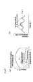
- the preliminary heating operation is not performed in an area Zb1 of the engine operation state where the torque is middle to high and the exhaust gas temperature is relatively high, while, in an area Zb2 where the torque is low and the exhaust gas temperature is relatively low, for instance, a control for heating up the exhaust gas such as intake throttling is performed, and as shown in Fig.8 (b), the catalyst temperature Td during the low torque operation is raised, to increase cases Xb where the catalyst temperature Td exceeds the catalyst active temperature Td1, and the filter can be regenerated by a regenerating operation including only post-injection without requiring a preliminary heating operation, in order to regenerate the filter.
- the preliminary heating operation is not performed in an area Zc1 of the engine operation state where the torque is high and the exhaust gas temperature is relatively high, while in areas Zc2, Zc3 where the torque is middle to low and the exhaust gas temperature is relatively low, for instance, a control for heating up the exhaust gas such as intake throttling, intake throttling + retard and so on, is performed.
- the catalyst temperature during the operation is raised, to obtain a case Xc where the catalyst temperature Td exceeds the catalyst active temperature Td1, across the whole engine operation area, so that the filter can be regenerated over the whole engine operation area including idling.
- Fig.7 to Fig.9 the division of operation areas in Fig.7 to Fig.9 is schematic and it may vary depending on the kind of engine, system of exhaust gas, atmospheric temperature, and so on.
- the means of control for heating up the exhaust gas for performing the preliminary heating operation was described taking intake throttling and intake throttling + retard as an example, it is not limited to them, but, in addition to the intake throttling, it can be composed of means, such as retard of the main injection timing of the fuel injection, post-injection (pot-injection), exhaust throttling, EGR, increase of load by driving an auxiliary, heating of exhaust gas by a heating means and so on, or combination of several of these means.
- this engine operation area can be set by combining load and engine rpm, and so on, and integrated into the control by map data, and so on. In addition, it can be corrected by the atmospheric temperature and so on in order to increase the precision more.
- continuously regenerating diesel particulate filter device though it has been described with a continuously regenerating diesel particulate filter device having a catalyst carried by the filter and at the same time provided with an oxidation catalyst on the upstream side of the filter, other than this, one can also have as object a continuously regenerating diesel particulate filter device having a catalyst carried by the filter, or a continuously regenerating diesel particulate filter device provided with an oxidation catalyst on the upstream side of the filter.
- the present invention has an object to provide a regeneration control method for continuously regenerating diesel particulate filter device allowing to regenerate the filter by removing PM efficiently, all the way limiting the deterioration in fuel consumption and at the same time preventing the drivability from deteriorating, by selecting an appropriate control for heating up the exhaust gas among control for heating up the exhaust gas prepared in a plurality of kinds, and shifting to a regenerating mode operation involving this control for heating up the exhaust gas, in a period appropriate for the regeneration treatment, even if the phase of clogging is on the middle order, through the observation of the state where PM is collected and engine exhaust gas temperature or catalyst temperature simultaneously, in a continuously regenerating diesel particulate filter device.
- the present invention can be used for a continuously regenerating diesel particulate filter device having a catalyst carried by the filter, a continuously regenerating diesel particulate filter device provided with an oxidation catalyst on the upstream side of the filter, and a continuously regenerating diesel particulate filter device having a catalyst carried by the filter and at the same time provided with an oxidation catalyst on the upstream side of the filter and thereby, can purify effectively the exhaust gas fro a vehicle and so on having these continuously regenerating diesel particulate filter devices on board, and prevent the air pollution.
Landscapes
- Engineering & Computer Science (AREA)
- Chemical & Material Sciences (AREA)
- Combustion & Propulsion (AREA)
- Mechanical Engineering (AREA)
- General Engineering & Computer Science (AREA)
- Chemical Kinetics & Catalysis (AREA)
- Processes For Solid Components From Exhaust (AREA)
- Combined Controls Of Internal Combustion Engines (AREA)
- Electrical Control Of Air Or Fuel Supplied To Internal-Combustion Engine (AREA)
- Filtering Materials (AREA)
- Filtering Of Dispersed Particles In Gases (AREA)
- Exhaust Gas Treatment By Means Of Catalyst (AREA)
Applications Claiming Priority (3)
| Application Number | Priority Date | Filing Date | Title |
|---|---|---|---|
| JP2001192387A JP4161546B2 (ja) | 2001-06-26 | 2001-06-26 | 連続再生型ディーゼルパティキュレートフィルタ装置の再生制御方法 |
| JP2001192387 | 2001-06-26 | ||
| PCT/JP2002/006375 WO2003001038A1 (fr) | 2001-06-26 | 2002-06-26 | Procede de commande de regeneration pour dispositif de filtrage particulaire diesel a regeneration |
Publications (3)
| Publication Number | Publication Date |
|---|---|
| EP1400663A1 true EP1400663A1 (fr) | 2004-03-24 |
| EP1400663A4 EP1400663A4 (fr) | 2004-07-21 |
| EP1400663B1 EP1400663B1 (fr) | 2005-11-09 |
Family
ID=19030846
Family Applications (1)
| Application Number | Title | Priority Date | Filing Date |
|---|---|---|---|
| EP02741308A Expired - Lifetime EP1400663B1 (fr) | 2001-06-26 | 2002-06-26 | Procede de commande de regeneration pour dispositif de filtrage particulaire diesel a regeneration |
Country Status (6)
| Country | Link |
|---|---|
| US (2) | US6952918B2 (fr) |
| EP (1) | EP1400663B1 (fr) |
| JP (1) | JP4161546B2 (fr) |
| CN (1) | CN1289800C (fr) |
| DE (1) | DE60207249T2 (fr) |
| WO (1) | WO2003001038A1 (fr) |
Cited By (9)
| Publication number | Priority date | Publication date | Assignee | Title |
|---|---|---|---|---|
| WO2005088095A1 (fr) * | 2004-03-11 | 2005-09-22 | Toyota Jidosha Kabushiki Kaisha | Controleur de regeneration conçu pour un appareil d'epuration des gaz d'echappement d'un moteur a combustion interne |
| WO2006005863A1 (fr) * | 2004-06-23 | 2006-01-19 | Peugeot Citroen Automobiles Sa | Systeme d'aide a la regeneration de moyens de depollution pour moteur de vehicule automobile |
| FR2873163A1 (fr) * | 2004-07-15 | 2006-01-20 | Peugeot Citroen Automobiles Sa | Systeme de controle du fonctionnement d'un moteur diesel de vehicule automobile associe a un catalyseur d'oxydation |
| EP1512860A3 (fr) * | 2003-09-03 | 2006-03-29 | Isuzu Motors Limited | Système de purification de gaz d'échappement |
| US7493755B2 (en) | 2004-06-23 | 2009-02-24 | Peugeot Citroen Automobiles Sa | System for assisting the regeneration of depollution means for a motor vehicle engine |
| US7694511B2 (en) | 2004-06-23 | 2010-04-13 | Peugeot Citroen Automobiles Sa | System for controlling depollution means regeneration |
| EP2568134A4 (fr) * | 2010-05-07 | 2018-03-28 | Yanmar Co., Ltd. | Système d'épuration des gaz d'échappement |
| EP2568135A4 (fr) * | 2010-05-07 | 2018-04-04 | Yanmar Co., Ltd. | Système d'épuration des gaz d'échappement pour engin de chantier |
| DE102007016531B4 (de) | 2006-04-07 | 2019-04-25 | Subaru Corporation | Abgasreinigungsvorrichtung für einen Dieselmotor |
Families Citing this family (85)
| Publication number | Priority date | Publication date | Assignee | Title |
|---|---|---|---|---|
| JP4161546B2 (ja) * | 2001-06-26 | 2008-10-08 | いすゞ自動車株式会社 | 連続再生型ディーゼルパティキュレートフィルタ装置の再生制御方法 |
| JP4241032B2 (ja) * | 2002-12-26 | 2009-03-18 | 日産自動車株式会社 | ディーゼルエンジン用触媒の硫黄被毒解除制御装置 |
| US7328573B2 (en) * | 2003-01-07 | 2008-02-12 | Peugeot Citroen Automobiles Sa | Aid system for regeneration of a particle filter for an exhaust line |
| DE602004029979D1 (de) * | 2003-01-07 | 2010-12-23 | Peugeot Citroen Automobiles Sa | Unterstützungssystem zur regeneration einesteilchenfilters in einer auslassleitung eines dieselmotors |
| ITTO20030179A1 (it) * | 2003-03-11 | 2004-09-12 | Fiat Auto Spa | Procedimento per la rimozione del particolato dai gas |
| JP2004324454A (ja) * | 2003-04-22 | 2004-11-18 | Mitsubishi Motors Corp | 内燃機関の排気浄化装置 |
| FR2862100B1 (fr) * | 2003-11-07 | 2008-04-04 | Peugeot Citroen Automobiles Sa | Systeme d'aide a la regeneration de moyens de depollution integres dans une ligne d'echappement d'un vehicule |
| DE10354232A1 (de) * | 2003-11-20 | 2005-06-30 | J. Eberspächer GmbH & Co. KG | Abgasbehandlungssystem für eine Brennkraftmaschine, insbesondere Diesel-Brennkraftmaschine, und Verfahren zum Betreiben eines Abgasbehandlungssystems für eine Brennkraftmaschine |
| US6862881B1 (en) * | 2003-12-05 | 2005-03-08 | Caterpillar Inc | Method and apparatus for controlling regeneration of a particulate filter |
| JP4075795B2 (ja) * | 2003-12-19 | 2008-04-16 | 日産自動車株式会社 | ディーゼルエンジンの排気後処理装置 |
| JP4125255B2 (ja) * | 2004-03-11 | 2008-07-30 | トヨタ自動車株式会社 | 内燃機関の排気浄化装置 |
| JP4248427B2 (ja) * | 2004-03-11 | 2009-04-02 | トヨタ自動車株式会社 | 内燃機関排気浄化装置の粒子状物質再生制御装置 |
| JP4314134B2 (ja) * | 2004-03-11 | 2009-08-12 | トヨタ自動車株式会社 | 内燃機関排気浄化装置の粒子状物質再生制御装置 |
| JP4314135B2 (ja) * | 2004-03-11 | 2009-08-12 | トヨタ自動車株式会社 | 車載内燃機関の排気浄化装置 |
| JP4161930B2 (ja) | 2004-04-06 | 2008-10-08 | いすゞ自動車株式会社 | 排気ガス浄化システムの制御方法及び排気ガス浄化システム |
| JP4501720B2 (ja) * | 2004-05-12 | 2010-07-14 | 株式会社デンソー | 内燃機関の排気浄化装置 |
| FR2872204B1 (fr) * | 2004-06-23 | 2006-11-03 | Peugeot Citroen Automobiles Sa | Systeme d'aide a la regeneration de moyens de depollution integres dans une ligne d'echappement d'un moteur |
| FR2872203B1 (fr) * | 2004-06-23 | 2006-11-03 | Peugeot Citroen Automobiles Sa | Systeme d'aide a la regeneration de moyens de depollution |
| CN100491704C (zh) * | 2004-08-10 | 2009-05-27 | 日产自动车株式会社 | 柴油机微粒滤清器中微粒沉积量的推算装置及方法 |
| DE102005042764A1 (de) * | 2004-09-09 | 2006-04-27 | Denso Corp., Kariya | Abgasreinigungssystem für einen Verbrennungsmotor |
| JP4214982B2 (ja) * | 2004-10-12 | 2009-01-28 | トヨタ自動車株式会社 | 内燃機関の排気浄化装置 |
| JP2006125206A (ja) * | 2004-10-26 | 2006-05-18 | Ict:Kk | 内燃機関排気ガスの浄化方法およびその装置 |
| JP2006161718A (ja) * | 2004-12-08 | 2006-06-22 | Toyota Motor Corp | 内燃機関の排気浄化システム |
| FR2879242A1 (fr) * | 2004-12-13 | 2006-06-16 | Renault Sas | Procede de controle de la regeneration d'un filtre a particules electrostatique |
| FR2879654B1 (fr) * | 2004-12-20 | 2010-04-30 | Inst Francais Du Petrole | Procede de regeneration de filtre a particules avec dispositif a combustion catalytique et installation de filtration utilisant un tel procede |
| JP3824003B2 (ja) * | 2005-02-24 | 2006-09-20 | いすゞ自動車株式会社 | 排気ガス浄化システム |
| US7343735B2 (en) | 2005-05-02 | 2008-03-18 | Cummins, Inc. | Apparatus and method for regenerating an exhaust gas aftertreatment component of an internal combustion engine |
| US7533524B2 (en) * | 2005-05-18 | 2009-05-19 | Cummins Inc. | Method and apparatus for soot filter catalyst temperature control with oxygen flow constraint |
| DE102005029338A1 (de) | 2005-06-24 | 2007-02-08 | Emitec Gesellschaft Für Emissionstechnologie Mbh | Verfahren zum Betrieb einer Partikelfalle sowie Vorrichtung zur Durchführung des Verfahrens |
| US8261535B2 (en) * | 2005-06-30 | 2012-09-11 | GM Global Technology Operations LLC | Enhanced post injection control system for diesel particulate filters |
| JP4665633B2 (ja) | 2005-07-12 | 2011-04-06 | 株式会社デンソー | 内燃機関の排気浄化装置 |
| JP3988776B2 (ja) * | 2005-07-15 | 2007-10-10 | いすゞ自動車株式会社 | 排気ガス浄化システムの制御方法及び排気ガス浄化システム |
| US7284366B2 (en) * | 2005-09-28 | 2007-10-23 | Ford Global Technologies, Llc | System and method for operating an engine having an exhaust gas recirculation system |
| JP4977993B2 (ja) * | 2005-10-19 | 2012-07-18 | いすゞ自動車株式会社 | ディーゼルエンジンの排気浄化装置 |
| GB0603898D0 (en) * | 2006-02-28 | 2006-04-05 | Johnson Matthey Plc | Exhaust system comprising catalysed soot filter |
| JP4692334B2 (ja) * | 2006-03-07 | 2011-06-01 | 日産自動車株式会社 | 排気微粒子捕集用フィルタの再生制御装置 |
| RU2304014C1 (ru) * | 2006-04-14 | 2007-08-10 | Михаил Юрьевич Кудрявцев | Многосекционная фильтрующая установка кудрявцева |
| US8800268B2 (en) * | 2006-12-01 | 2014-08-12 | Basf Corporation | Zone coated filter, emission treatment systems and methods |
| US7472610B2 (en) * | 2006-12-08 | 2009-01-06 | Cummins Filtration Ip, Inc | Apparatus, system, and method for differential pressure measurement across a conduit flow area change |
| JP2008150955A (ja) * | 2006-12-14 | 2008-07-03 | Denso Corp | 排気還流装置 |
| JP4232823B2 (ja) | 2006-12-26 | 2009-03-04 | トヨタ自動車株式会社 | 内燃機関の排気浄化装置 |
| DE102007019460A1 (de) * | 2007-04-25 | 2008-11-06 | Man Nutzfahrzeuge Ag | Abgasnachbehandlungssystem |
| JP4844467B2 (ja) * | 2007-05-07 | 2011-12-28 | 日産自動車株式会社 | 内燃機関の排気浄化装置 |
| US7856808B2 (en) * | 2007-06-25 | 2010-12-28 | Detroit Diesel Corporation | Method to re-open ash filled channels in diesel particulate filters |
| JP4930215B2 (ja) * | 2007-06-25 | 2012-05-16 | 株式会社デンソー | 排気浄化装置 |
| JP5053015B2 (ja) * | 2007-09-25 | 2012-10-17 | 日立建機株式会社 | 建設機械の排気ガス浄化システム |
| US7657364B2 (en) * | 2007-10-10 | 2010-02-02 | Cummins IP. Inc | Apparatus, system, and method for thermal management of an engine comprising a continuously variable transmission |
| US7558668B2 (en) * | 2007-11-30 | 2009-07-07 | Caterpillar Inc. | Exhaust system having temperature sensor verification |
| US20090139211A1 (en) * | 2007-12-03 | 2009-06-04 | International Engine Intellectual Property Company, Llc | Timer-based warning structure for detecting and indicating an overloaded diesel particulate filter |
| US9993771B2 (en) | 2007-12-12 | 2018-06-12 | Basf Corporation | Emission treatment catalysts, systems and methods |
| US9863297B2 (en) * | 2007-12-12 | 2018-01-09 | Basf Corporation | Emission treatment system |
| US8091345B2 (en) * | 2008-02-06 | 2012-01-10 | Cummins Ip, Inc | Apparatus, system, and method for efficiently increasing exhaust flow temperature for an internal combustion engine |
| KR100957275B1 (ko) | 2008-03-21 | 2010-05-12 | 현대자동차주식회사 | 차량 배기 계의 후 처리 장치를 구성하는 매연 여과 필터의다단 재생 방법 |
| US8156730B2 (en) * | 2008-04-29 | 2012-04-17 | Cummins, Inc. | Engine performance management during a diesel particulate filter regeneration event |
| US8322132B2 (en) * | 2008-04-30 | 2012-12-04 | Perkins Engines Company Limited | Exhaust treatment system implementing regeneration control |
| US8375705B2 (en) | 2008-05-30 | 2013-02-19 | Caterpillar Inc. | Exhaust system implementing low-temperature regeneration strategy |
| US8196392B2 (en) * | 2008-05-30 | 2012-06-12 | Caterpillar Inc. | Exhaust system having regeneration temperature control strategy |
| US8302385B2 (en) * | 2008-05-30 | 2012-11-06 | Cummins Ip, Inc. | Apparatus, system, and method for controlling engine exhaust temperature |
| US8234857B2 (en) * | 2008-06-23 | 2012-08-07 | Caterpillar Inc. | Air supply system for a regeneration assembly |
| EP2143918B1 (fr) | 2008-07-11 | 2014-10-22 | Perkins Engines Company Limited | Système de décontamination post-traitement |
| DE102008037156A1 (de) * | 2008-08-08 | 2010-02-18 | Audi Ag | Verfahren und eine Vorrichtung zur Reinigung eines Abgasstroms einer magerlauffähigen Brennkraftmaschine |
| JP2010053723A (ja) * | 2008-08-26 | 2010-03-11 | Yanmar Co Ltd | 排気浄化装置 |
| JP5600390B2 (ja) * | 2008-12-17 | 2014-10-01 | 日産自動車株式会社 | 内燃機関の排気浄化装置 |
| US8388712B2 (en) * | 2009-02-12 | 2013-03-05 | Ford Global Technologies, Llc | Particulate matter retaining and purging system |
| US9371754B2 (en) * | 2009-03-12 | 2016-06-21 | Caterpillar Inc. | Diesel particulate filter regeneration control and method |
| US8607549B2 (en) * | 2009-07-31 | 2013-12-17 | Ford Global Technologies, Llc | Controlling regeneration of an emission control device |
| JP2011032975A (ja) * | 2009-08-04 | 2011-02-17 | Yanmar Co Ltd | ディーゼル機関における排気ガス浄化装置 |
| JP5155979B2 (ja) * | 2009-10-21 | 2013-03-06 | ヤンマー株式会社 | ディーゼルエンジン |
| KR20110062127A (ko) * | 2009-12-02 | 2011-06-10 | 현대자동차주식회사 | 매연필터의 재생 제어방법 |
| US8631642B2 (en) * | 2009-12-22 | 2014-01-21 | Perkins Engines Company Limited | Regeneration assist calibration |
| US8464523B2 (en) * | 2010-03-12 | 2013-06-18 | GM Global Technology Operations LLC | Targeted particulate matter filter regeneration system |
| SE535930C2 (sv) * | 2010-06-21 | 2013-02-26 | Scania Cv Ab | Förfarande och anordning för undvikande av överhettning hos en doseringsenhet vid ett SCR-system |
| SE535931C2 (sv) * | 2010-06-21 | 2013-02-26 | Scania Cv Ab | Förfarande och anordning för undvikande av överhettning hos en doseringsenhet vid ett HC-doseringssystem |
| US8444730B2 (en) * | 2010-09-27 | 2013-05-21 | Ford Global Technologies, Llc | Even-loading DPF and regeneration thereof |
| US8447461B2 (en) * | 2010-10-01 | 2013-05-21 | Deere & Company | Particulate filter ash loading prediction method and vehicle with same |
| US9151206B2 (en) * | 2011-02-28 | 2015-10-06 | Ford Global Technologies, Llc | Method for determining soot mass stored with a particulate filter |
| KR101326812B1 (ko) * | 2011-05-17 | 2013-11-07 | 현대자동차 주식회사 | 배기가스 후처리 방법 |
| US9534551B2 (en) * | 2011-09-27 | 2017-01-03 | Kubota Corporation | Working machine |
| JP5588027B2 (ja) * | 2013-01-21 | 2014-09-10 | ヤンマー株式会社 | エンジン |
| JP6650675B2 (ja) * | 2014-02-26 | 2020-02-19 | エフピーティー インダストリアル エス ピー エー | 内燃機関の排気ガス後処理システムの管路内の未燃焼炭化水素の蓄積を防ぐシステム |
| JP6384196B2 (ja) * | 2014-08-20 | 2018-09-05 | いすゞ自動車株式会社 | 排気浄化装置の再生装置 |
| JP6424618B2 (ja) * | 2014-12-26 | 2018-11-21 | いすゞ自動車株式会社 | 排気浄化システム |
| KR101713743B1 (ko) * | 2015-12-08 | 2017-03-08 | 현대자동차 주식회사 | 선택적 환원 촉매가 코팅된 디젤 매연 필터의 재생 방법 및 배기 가스 정화 장치 |
| EP3460222B1 (fr) * | 2017-09-21 | 2020-05-06 | FCA Italy S.p.A. | Procédé, système et produit-programme d'ordinateur pour commander la combustion de particules pendant la régénération d'un filtre à particules d'un moteur diesel |
| CN107762653B (zh) * | 2017-10-10 | 2020-03-17 | 中国第一汽车股份有限公司 | 柴油机氧化催化器温度控制系统 |
Family Cites Families (23)
| Publication number | Priority date | Publication date | Assignee | Title |
|---|---|---|---|---|
| DE3232729A1 (de) * | 1982-09-03 | 1984-03-08 | Degussa Ag, 6000 Frankfurt | Verfahren zur herabsetzung der zuendtemperatur von aus dem abgas von dieselmotoren herausgefiltertem dieselruss |
| JPS6170114A (ja) * | 1984-09-12 | 1986-04-10 | Nissan Motor Co Ltd | 内燃機関の排気微粒子処理装置 |
| JPH01105719A (ja) | 1987-10-19 | 1989-04-24 | Komatsu Ltd | 取り出し装置 |
| JPH01105719U (fr) * | 1988-01-09 | 1989-07-17 | ||
| DE69505729T2 (de) * | 1994-05-12 | 1999-06-24 | Isuzu Ceramics Research Institute Co., Ltd., Fujisawa, Kanagawa | Dieselpartikelfilter |
| JP3199970B2 (ja) | 1994-12-22 | 2001-08-20 | 株式会社デンソー | エンジンの排気浄化装置 |
| JP3864436B2 (ja) | 1995-08-30 | 2006-12-27 | 株式会社豊田自動織機 | 内燃機関の排気浄化装置 |
| JPH09222009A (ja) | 1996-02-15 | 1997-08-26 | Nippon Soken Inc | 内燃機関の排気微粒子浄化装置 |
| JPH10259711A (ja) | 1997-03-19 | 1998-09-29 | Mitsubishi Automob Eng Co Ltd | エンジンの排気浄化装置 |
| JP3390641B2 (ja) | 1997-09-29 | 2003-03-24 | 日野自動車株式会社 | パティキュレート除去装置 |
| US6237326B1 (en) * | 1999-08-24 | 2001-05-29 | Ford Global Technolgies, Inc. | Engine control system and method with lean catalyst and particulate filter |
| DE19952830A1 (de) * | 1999-11-02 | 2001-05-03 | Audi Ag | Verfahren zur Abgasnachbehandlung durch Nacheinspritzung von Kraftstoff bei einer Diesel-Brennkraftmaschine mit Vorkatalysator und Partikelfilter |
| US6304815B1 (en) * | 2000-03-29 | 2001-10-16 | Ford Global Technologies, Inc. | Method for controlling an exhaust gas temperature of an engine for improved performance of exhaust aftertreatment systems |
| EP1205647B1 (fr) * | 2000-11-03 | 2003-03-05 | Ford Global Technologies, Inc., A subsidiary of Ford Motor Company | Procédé de régénération le filtre à particules d'un moteur Diesel |
| DE10056016A1 (de) * | 2000-11-11 | 2002-05-16 | Bosch Gmbh Robert | Verfahren und Vorrichtung zur Steuerung eines Abgasnachbehandlungssystems |
| US6622480B2 (en) * | 2001-02-21 | 2003-09-23 | Isuzu Motors Limited | Diesel particulate filter unit and regeneration control method of the same |
| JP3707395B2 (ja) * | 2001-04-26 | 2005-10-19 | トヨタ自動車株式会社 | 排気ガス浄化装置 |
| JP4161546B2 (ja) * | 2001-06-26 | 2008-10-08 | いすゞ自動車株式会社 | 連続再生型ディーゼルパティキュレートフィルタ装置の再生制御方法 |
| JP3879833B2 (ja) * | 2002-03-04 | 2007-02-14 | 三菱自動車工業株式会社 | 内燃機関の排気浄化装置 |
| DE10213170A1 (de) * | 2002-03-23 | 2003-10-02 | Daimler Chrysler Ag | Betriebsverfahren für eine mit einem Abgasnachbehandlungssystem arbeitende Brennkraftmaschine |
| JP3870815B2 (ja) * | 2002-03-29 | 2007-01-24 | 日産自動車株式会社 | 内燃機関の排気浄化装置 |
| JP4007085B2 (ja) * | 2002-06-13 | 2007-11-14 | 株式会社デンソー | 内燃機関の排ガス浄化装置 |
| US6651638B1 (en) * | 2002-06-28 | 2003-11-25 | Cummins Engine Company, Inc. | System and method for derating an engine to encourage servicing of a vehicle |
-
2001
- 2001-06-26 JP JP2001192387A patent/JP4161546B2/ja not_active Expired - Fee Related
-
2002
- 2002-06-26 DE DE60207249T patent/DE60207249T2/de not_active Expired - Lifetime
- 2002-06-26 WO PCT/JP2002/006375 patent/WO2003001038A1/fr not_active Ceased
- 2002-06-26 US US10/416,714 patent/US6952918B2/en not_active Expired - Fee Related
- 2002-06-26 EP EP02741308A patent/EP1400663B1/fr not_active Expired - Lifetime
- 2002-06-26 CN CNB028117999A patent/CN1289800C/zh not_active Expired - Fee Related
-
2005
- 2005-09-01 US US11/216,093 patent/US7086220B2/en not_active Expired - Fee Related
Cited By (14)
| Publication number | Priority date | Publication date | Assignee | Title |
|---|---|---|---|---|
| EP1512860A3 (fr) * | 2003-09-03 | 2006-03-29 | Isuzu Motors Limited | Système de purification de gaz d'échappement |
| US7841169B2 (en) | 2004-03-11 | 2010-11-30 | Toyota Jidosha Kabushiki Kaisha | Regeneration controller for exhaust purification apparatus of internal combustion engine |
| WO2005088095A1 (fr) * | 2004-03-11 | 2005-09-22 | Toyota Jidosha Kabushiki Kaisha | Controleur de regeneration conçu pour un appareil d'epuration des gaz d'echappement d'un moteur a combustion interne |
| KR100817863B1 (ko) * | 2004-03-11 | 2008-03-31 | 도요다 지도샤 가부시끼가이샤 | 내연기관의 배기정화장치용 재생제어장치 |
| US7694511B2 (en) | 2004-06-23 | 2010-04-13 | Peugeot Citroen Automobiles Sa | System for controlling depollution means regeneration |
| WO2006005863A1 (fr) * | 2004-06-23 | 2006-01-19 | Peugeot Citroen Automobiles Sa | Systeme d'aide a la regeneration de moyens de depollution pour moteur de vehicule automobile |
| US7493755B2 (en) | 2004-06-23 | 2009-02-24 | Peugeot Citroen Automobiles Sa | System for assisting the regeneration of depollution means for a motor vehicle engine |
| US7596942B2 (en) | 2004-06-23 | 2009-10-06 | Peugeot Citroen Automobiles Sa | System for assisting regeneration of pollution management means for motor vehicle engine |
| WO2006016080A1 (fr) * | 2004-07-15 | 2006-02-16 | Peugeot Citroen Automobiles Sa | Systeme de controle du fonctionnement d'un moteur diesel de vehicule automobile associe a un catalyseur d'oxydation |
| US7823377B2 (en) | 2004-07-15 | 2010-11-02 | Peugeot Citroen Automobiles Sa | System for controlling the function of a diesel engine in a motor vehicle connected to an oxidation catalyst |
| FR2873163A1 (fr) * | 2004-07-15 | 2006-01-20 | Peugeot Citroen Automobiles Sa | Systeme de controle du fonctionnement d'un moteur diesel de vehicule automobile associe a un catalyseur d'oxydation |
| DE102007016531B4 (de) | 2006-04-07 | 2019-04-25 | Subaru Corporation | Abgasreinigungsvorrichtung für einen Dieselmotor |
| EP2568134A4 (fr) * | 2010-05-07 | 2018-03-28 | Yanmar Co., Ltd. | Système d'épuration des gaz d'échappement |
| EP2568135A4 (fr) * | 2010-05-07 | 2018-04-04 | Yanmar Co., Ltd. | Système d'épuration des gaz d'échappement pour engin de chantier |
Also Published As
| Publication number | Publication date |
|---|---|
| DE60207249T2 (de) | 2006-07-06 |
| JP2003003833A (ja) | 2003-01-08 |
| US20040035101A1 (en) | 2004-02-26 |
| WO2003001038A1 (fr) | 2003-01-03 |
| DE60207249D1 (de) | 2005-12-15 |
| US20050284138A1 (en) | 2005-12-29 |
| EP1400663A4 (fr) | 2004-07-21 |
| EP1400663B1 (fr) | 2005-11-09 |
| US7086220B2 (en) | 2006-08-08 |
| JP4161546B2 (ja) | 2008-10-08 |
| CN1514906A (zh) | 2004-07-21 |
| US6952918B2 (en) | 2005-10-11 |
| CN1289800C (zh) | 2006-12-13 |
Similar Documents
| Publication | Publication Date | Title |
|---|---|---|
| EP1400663B1 (fr) | Procede de commande de regeneration pour dispositif de filtrage particulaire diesel a regeneration | |
| EP1234959B1 (fr) | Unité de filtre à particules Diesel et méthode de régulation pour sa régénération | |
| CN100572768C (zh) | 排气净化系统 | |
| US7721534B2 (en) | Control method for an exhaust gas purification system and an exhaust gas purification system | |
| EP1400664B1 (fr) | Méthode et dispositif de purification de gaz d'échappement | |
| JPWO2002066813A1 (ja) | ディーゼルエンジンの燃料噴射制御方法と排気ガス後処理装置の再生制御方法 | |
| JP3988776B2 (ja) | 排気ガス浄化システムの制御方法及び排気ガス浄化システム | |
| US20060107649A1 (en) | Apparatus and method for clarifying exhaust gas of diesel engine | |
| JP2008274835A (ja) | 酸化触媒の劣化診断装置 | |
| WO2007049406A1 (fr) | Procede de regulation d’un systeme de purification de gaz d'echappement et systeme de purification de gaz d'echappement | |
| JP2001280121A (ja) | 連続再生型パティキュレートフィルタ装置 | |
| JP4320586B2 (ja) | 内燃機関の排気浄化装置 | |
| JP4466158B2 (ja) | 排気ガス浄化システムの制御方法及び排気ガス浄化システム | |
| JP4070687B2 (ja) | 排気浄化装置 | |
| JP4311253B2 (ja) | 排気ガス浄化システムの制御方法及び排気ガス浄化システム | |
| JP3951619B2 (ja) | 連続再生型ディーゼルパティキュレートフィルタ装置及びその再生制御方法 | |
| JP4070681B2 (ja) | 排気浄化装置 | |
| JP4081419B2 (ja) | 排気浄化装置 | |
| JP4235509B2 (ja) | 排気浄化装置 | |
| JP2007023876A (ja) | 排気ガス浄化システムの制御方法及び排気ガス浄化システム | |
| JP2007162567A (ja) | エンジン排ガスフィルタの再生時期制御装置及び再生時期制御方法 | |
| JP2005061363A (ja) | 排気浄化装置 |
Legal Events
| Date | Code | Title | Description |
|---|---|---|---|
| PUAI | Public reference made under article 153(3) epc to a published international application that has entered the european phase |
Free format text: ORIGINAL CODE: 0009012 |
|
| 17P | Request for examination filed |
Effective date: 20030426 |
|
| AK | Designated contracting states |
Kind code of ref document: A1 Designated state(s): AT BE CH CY DE DK ES FI FR GB GR IE IT LI LU MC NL PT SE TR |
|
| A4 | Supplementary search report drawn up and despatched |
Effective date: 20040609 |
|
| RIC1 | Information provided on ipc code assigned before grant |
Ipc: 7F 01N 9/00 B Ipc: 7F 01N 3/023 B Ipc: 7F 01N 3/035 B Ipc: 7F 02D 41/02 B Ipc: 7F 01N 3/02 A |
|
| 17Q | First examination report despatched |
Effective date: 20040902 |
|
| GRAP | Despatch of communication of intention to grant a patent |
Free format text: ORIGINAL CODE: EPIDOSNIGR1 |
|
| RBV | Designated contracting states (corrected) |
Designated state(s): DE FR GB |
|
| GRAS | Grant fee paid |
Free format text: ORIGINAL CODE: EPIDOSNIGR3 |
|
| GRAA | (expected) grant |
Free format text: ORIGINAL CODE: 0009210 |
|
| AK | Designated contracting states |
Kind code of ref document: B1 Designated state(s): DE FR GB |
|
| REG | Reference to a national code |
Ref country code: GB Ref legal event code: FG4D |
|
| REF | Corresponds to: |
Ref document number: 60207249 Country of ref document: DE Date of ref document: 20051215 Kind code of ref document: P |
|
| ET | Fr: translation filed | ||
| PLBE | No opposition filed within time limit |
Free format text: ORIGINAL CODE: 0009261 |
|
| STAA | Information on the status of an ep patent application or granted ep patent |
Free format text: STATUS: NO OPPOSITION FILED WITHIN TIME LIMIT |
|
| 26N | No opposition filed |
Effective date: 20060810 |
|
| PGFP | Annual fee paid to national office [announced via postgrant information from national office to epo] |
Ref country code: GB Payment date: 20130626 Year of fee payment: 12 Ref country code: DE Payment date: 20130619 Year of fee payment: 12 |
|
| PGFP | Annual fee paid to national office [announced via postgrant information from national office to epo] |
Ref country code: FR Payment date: 20130624 Year of fee payment: 12 |
|
| REG | Reference to a national code |
Ref country code: DE Ref legal event code: R119 Ref document number: 60207249 Country of ref document: DE |
|
| GBPC | Gb: european patent ceased through non-payment of renewal fee |
Effective date: 20140626 |
|
| REG | Reference to a national code |
Ref country code: FR Ref legal event code: ST Effective date: 20150227 |
|
| REG | Reference to a national code |
Ref country code: DE Ref legal event code: R119 Ref document number: 60207249 Country of ref document: DE Effective date: 20150101 |
|
| PG25 | Lapsed in a contracting state [announced via postgrant information from national office to epo] |
Ref country code: DE Free format text: LAPSE BECAUSE OF NON-PAYMENT OF DUE FEES Effective date: 20150101 |
|
| PG25 | Lapsed in a contracting state [announced via postgrant information from national office to epo] |
Ref country code: GB Free format text: LAPSE BECAUSE OF NON-PAYMENT OF DUE FEES Effective date: 20140626 Ref country code: FR Free format text: LAPSE BECAUSE OF NON-PAYMENT OF DUE FEES Effective date: 20140630 |