EP1400748B1 - Kfz-Scheinwerfer mit einem Spiegel und dazu konjugiertem Umlenkelement zur Erzeugung eines Lichtbündels mit einer nicht horizontalen Hell-Dunkelgrenze - Google Patents
Kfz-Scheinwerfer mit einem Spiegel und dazu konjugiertem Umlenkelement zur Erzeugung eines Lichtbündels mit einer nicht horizontalen Hell-Dunkelgrenze Download PDFInfo
- Publication number
- EP1400748B1 EP1400748B1 EP03292245A EP03292245A EP1400748B1 EP 1400748 B1 EP1400748 B1 EP 1400748B1 EP 03292245 A EP03292245 A EP 03292245A EP 03292245 A EP03292245 A EP 03292245A EP 1400748 B1 EP1400748 B1 EP 1400748B1
- Authority
- EP
- European Patent Office
- Prior art keywords
- reflector
- mirror
- vertical
- plane
- headlight apparatus
- Prior art date
- Legal status (The legal status is an assumption and is not a legal conclusion. Google has not performed a legal analysis and makes no representation as to the accuracy of the status listed.)
- Expired - Lifetime
Links
- 230000003287 optical effect Effects 0.000 claims description 34
- 238000009826 distribution Methods 0.000 claims description 5
- 238000000926 separation method Methods 0.000 claims 1
- 238000010276 construction Methods 0.000 description 8
- 238000004519 manufacturing process Methods 0.000 description 8
- 235000021183 entrée Nutrition 0.000 description 7
- 238000012986 modification Methods 0.000 description 6
- 230000004048 modification Effects 0.000 description 6
- 238000011084 recovery Methods 0.000 description 4
- 229920000297 Rayon Polymers 0.000 description 3
- 230000006399 behavior Effects 0.000 description 3
- 238000000034 method Methods 0.000 description 3
- 230000005855 radiation Effects 0.000 description 3
- 239000002964 rayon Substances 0.000 description 3
- 241001080024 Telles Species 0.000 description 2
- 240000008042 Zea mays Species 0.000 description 2
- 230000004907 flux Effects 0.000 description 2
- 230000006872 improvement Effects 0.000 description 2
- 238000003754 machining Methods 0.000 description 2
- 241000897276 Termes Species 0.000 description 1
- 230000008901 benefit Effects 0.000 description 1
- 230000009977 dual effect Effects 0.000 description 1
- 229940082150 encore Drugs 0.000 description 1
- 239000000463 material Substances 0.000 description 1
- 239000002184 metal Substances 0.000 description 1
- 230000007935 neutral effect Effects 0.000 description 1
- 244000045947 parasite Species 0.000 description 1
- 238000005375 photometry Methods 0.000 description 1
- 239000000047 product Substances 0.000 description 1
- 230000001105 regulatory effect Effects 0.000 description 1
- 230000000717 retained effect Effects 0.000 description 1
- 230000007480 spreading Effects 0.000 description 1
- 238000003892 spreading Methods 0.000 description 1
- 239000013589 supplement Substances 0.000 description 1
Images

Classifications
-
- F—MECHANICAL ENGINEERING; LIGHTING; HEATING; WEAPONS; BLASTING
- F21—LIGHTING
- F21S—NON-PORTABLE LIGHTING DEVICES; SYSTEMS THEREOF; VEHICLE LIGHTING DEVICES SPECIALLY ADAPTED FOR VEHICLE EXTERIORS
- F21S41/00—Illuminating devices specially adapted for vehicle exteriors, e.g. headlamps
- F21S41/30—Illuminating devices specially adapted for vehicle exteriors, e.g. headlamps characterised by reflectors
- F21S41/32—Optical layout thereof
- F21S41/33—Multi-surface reflectors, e.g. reflectors with facets or reflectors with portions of different curvature
- F21S41/334—Multi-surface reflectors, e.g. reflectors with facets or reflectors with portions of different curvature the reflector consisting of patch like sectors
- F21S41/336—Multi-surface reflectors, e.g. reflectors with facets or reflectors with portions of different curvature the reflector consisting of patch like sectors with discontinuity at the junction between adjacent areas
-
- F—MECHANICAL ENGINEERING; LIGHTING; HEATING; WEAPONS; BLASTING
- F21—LIGHTING
- F21S—NON-PORTABLE LIGHTING DEVICES; SYSTEMS THEREOF; VEHICLE LIGHTING DEVICES SPECIALLY ADAPTED FOR VEHICLE EXTERIORS
- F21S41/00—Illuminating devices specially adapted for vehicle exteriors, e.g. headlamps
- F21S41/20—Illuminating devices specially adapted for vehicle exteriors, e.g. headlamps characterised by refractors, transparent cover plates, light guides or filters
- F21S41/28—Cover glass
-
- F—MECHANICAL ENGINEERING; LIGHTING; HEATING; WEAPONS; BLASTING
- F21—LIGHTING
- F21S—NON-PORTABLE LIGHTING DEVICES; SYSTEMS THEREOF; VEHICLE LIGHTING DEVICES SPECIALLY ADAPTED FOR VEHICLE EXTERIORS
- F21S41/00—Illuminating devices specially adapted for vehicle exteriors, e.g. headlamps
- F21S41/20—Illuminating devices specially adapted for vehicle exteriors, e.g. headlamps characterised by refractors, transparent cover plates, light guides or filters
- F21S41/25—Projection lenses
Definitions
- the present invention relates to a motor vehicle headlamp device comprising essentially a mirror and a conjugate deflection element whose design is such that it produces a light beam whose cut is not flat.
- the object of the invention is essentially to propose an improvement in an existing projector device, this improvement consisting in the introduction of modifications of the surfaces of the mirror and / or of the deflection element so as to obtain a non-flat cut of the light beam. product.
- the projector device initially designed as an anti-fog, can thus be used in particular as a code-type projector device.
- the projector device according to the invention finds its application mainly in use as dipped beam, because it fully meets the standards for this type of lights. It could nevertheless be used in any other projector device mentioned that would know normative evolutions. Describing the invention in the context of low beam is therefore in no way limiting to this application alone.
- the first family is that of so-called parabolic projectors.
- a light beam is generated by a small light source disposed in a reflector, or mirror.
- the projection on the road of the light rays reflected by a suitable reflector makes it possible to directly obtain a light beam obeying the various constraints imposed by the standards.
- Such a projector device may optionally be supplemented by an ice-type exit surface, which may be provided for example with ridges for modifying the light beam, for example by spreading it in width.
- This family of projectors includes so-called free-surface projectors, or complex surfaces, which make it possible to obtain directly a light beam having a desired cut-off or cut-line.
- cut line is meant the boundary between a low area illuminated by the projector device and a high area that is not illuminated by the projector device.
- This type of projectors is particularly efficient in terms of reduced depth and light distribution.
- One of the difficulties encountered in their realization is that it is necessary for their mirror to recover a large proportion of the light signals produced by the light source, otherwise it will produce an insufficiently intense light beam.
- the first solution is to use a very small basic focal distance, in order to obtain a very closed mirror around the light source and not bulky in width; but because of the size - important in this case - images of the light source generated by the mirror, the light beam is then too thick, and therefore difficult to control.
- the second solution is to increase the basic focal distance, but the mirror then has significant dimensions transverse to the optical axis, the projector device is then no longer compact.
- the second family is that of so-called elliptical projectors.
- a spot of light concentration is generated by a light source arranged in a mirror.
- the light source is disposed at the first focus of a mirror shaped ellipsoid of revolution, said spot forming at the second focus of the mirror.
- the spot of light concentration is then projected onto the road by a convergent lens, for example a plano-convex lens.
- the light concentration spot is partially obscured, for example by means of a metal cover disposed within the projector device.
- This type of projector is particularly efficient in terms of recovery of the light signals emitted by the light source; its dimensions transverse to the optical axis are also relatively small, which is also an advantage.
- this type of projector has a large footprint in depth, and photometry is difficult to control because no corrective element having streaks can correct the light beam from the lens.
- EP-1225386 a projector that attempts to meet the criteria outlined above.
- This projector in addition to a reflector and a light source, comprises a concave or convex lens in vertical or transverse section. The light passing through the lens is refracted significantly and it is therefore difficult to see the interior of the projector.
- a particular projector device has recently been proposed, which will be referred to as a basic hybrid projector.
- the basic hybrid projector while technically belonging to the family of parabolic projectors - it does not have a cache to create a cut - present, off, an outer appearance closer to the elliptical projectors than are the conventional parabolic floodlights.
- the proposed basic hybrid projector device also produces a good quality light beam.
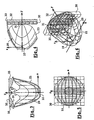
- the principle of construction of the basic hybrid projector device is schematically represented, in an axial horizontal section, in FIG. 1. Only the construction of a lateral half of the basic hybrid projector is illustrated, while the other half can be constructed with the same teachings. , symmetrically or not.
- O is at the geometric center of a light source 10
- YY is the optical axis
- XX is the horizontal axis transverse to the optical axis of the projector
- ZZ is the vertical axis.
- the projector device is essentially composed of a lamp housing the light source 10, a mirror 20 and a transparent optical deflection element 30, called here a lens, placed in front of the mirror 20.
- the mirror 20 is able to cooperate with the light source 10 for generating a beam delimited by a cut line, and the deflection element 30 is able to ensure a horizontal spread of the light, without substantially changing the vertical distribution of light.
- the light beam produced by a projector device is constituted by a superposition of all the images of the light source after reflection of the light signals that it emits on the reflecting surface of the mirror 10 and after passing through the lens 30.
- a generator 21 of which describes a curve y f 20 (x) which will be explained later.
- the lens 30 is disposed transversely to the axis OY and has an inner face 31, or input face, receiving the light reflected by the mirror and an outer face 32, or output face, smooth, flat and perpendicular to the OY axis.
- the lens 30 is obtained by moving a vertical director along this curve to form its inner face, the lens thus being cylindrical.
- the mirror 20, respectively the inner face 31 of the lens 30, is manufactured according to a desired behavior in terms of propagation of the reflected rays, respectively refracted.
- D / 2 denotes the half-width of the mirror 20 and of the lens 30.
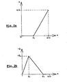
- the horizontal generator of the mirror 20 is constructed to satisfy a given law, an example of which is given in FIG. 2a, giving a dimension X (x), which is therefore a function of the abscissa x.
- the horizontal generator 21 of the mirror 20 is progressively evolving, from the dimension x1, from an elliptical pace to a parabolic pace.
- the lens which is represented in solid lines in its theoretical form with a square outline, is made with a circular outline 33 shown in dashed lines in FIG. 6.
- the off-axis hybrid projector device presents, because of its smooth faces and because of its circular outline, a similar appearance and shape to a lens usually used in elliptical projectors devices.
- the contour 23 of the mirror 20 is made so as to eliminate therefrom any zone capable of reflecting the light towards the outside of the circular contour 33 of the lens.
- the hybrid projector device as just described is therefore a compact projector in width and depth, capable of generating a beam satisfactory in terms of intensity due to the small loss of light signals within the hybrid projector device, and having an appearance similar to that of an elliptical.
- the images of the light source created by these turned parts thus producing a group of light rays, within the light beam produced by the projector device, which give rise to a cut which is no longer flat, and which can meet the standards regulating European and / or American codes.
- the role of the lens 30 is to spread out horizontally the light rays that arrive on its inner face after reflection on the mirror 20. Turning a portion of the mirror 20 would therefore not cause a shift on the cut line, but a diffuse task over a large part of the width of the mirror. beam due to the horizontal spread caused by the lens.
- the invention proposes a vertical tilting of certain surface areas of the mirror and / or of the lens, so that the inclination of these zones is modified, thus causing an upward shift of some of the images, constituting the light beam, of the light source.
- the invention therefore essentially relates to a projector device comprising in particular a light source, a mirror having a reflective surface for reflecting light signals produced by the light source and comprising a horizontal generatrix moving from an elliptical pace to a parabolic pace, and an element transparent optical deflection having an input side of the reflected light signals and an output side of the reflected light signals, the transparent deflection element being placed in front of the mirror, the mirror being adapted to cooperate with the light source to generate a beam delimited by a cut line, and the deflection element being able to ensure a horizontal spread of the light signals produced by the light source and reflected by the mirror, without modifying the vertical distribution of the light signals, said projector device being characterized in that it comprises at least one recess provided on at least one of the surfaces encountered by the light signals to obtain a non-flat cutoff line of the light beam, the detachment consisting of at least one prism disposed on the transparent optical deflection element.
- Another object of the invention is a motor vehicle equipped with at least one projector device having at least one of the characteristics which have just been described.
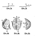
- a new mirror 80 is obtained, a possible example of which is shown in FIGS. 8a (front view of the mirror) at 8c according to different views.
- recesses are introduced on this surface.
- the reflecting surface of the mirror 80 is a juxtaposition of a set of adjacent vertical strips, a recess here means a tilting of one of these vertical strips.
- a left lateral vertical band 81 which corresponds to the left end of the reflecting surface of the mirror
- a vertical band right lateral 82 which corresponds to the right end of the reflecting surface of the mirror
- a central vertical strip 83 which corresponds to a strip adjacent to a vertical central axis 84 of the mirror.
- the tilting of the lateral strips 81 and 82 makes it possible to obtain, in the light beam produced by the projector according to the invention, the recovery of small images of the light source disposed at the heart of the mirror, these images being of intensity quite important. This produces a rupture of the type of rupture 70 of FIG. 7a.
- the tilting of the central band 83 makes it possible to obtain the recovery of larger images of the light source, but of lesser intensity, thus making it possible to obtain a cutoff line of the type of the cutoff line 71.
- central side is located just to the left or just to the right of the central vertical axis 84 depending on the side where it is desired to go up the cut line 71.
- the inclination of the strips lateral 81 and 82 is of the order of 3 degrees relative to the sidebands adjacent thereto, the inclination of the central strip 83 being of the order of 1 degree relative to the bands adjacent thereto.
- the left lateral band between the abscissa -40 millimeters and -35 millimeters is available, the right lateral band between the abscissa 35 millimeters and 40 millimeters is arranged, and it is available the central band between abscissa -10 mm and 0 mm.
- the tilting of the strips is preferably carried out so that connecting surfaces between the tilted strips and their adjacent strips are exposed as little as possible to the light rays produced by the light source, so as not to introduce too many parasites into the beam. light beam produced.
- the prisms arranged on the extreme lateral strips of the exit face of the lens are intended to trace small intense images of the light source to create the rupture 70, the prism arranged on a central strip being intended to ensure the extension of this rupture by noting larger but less intense images of the light source.
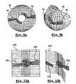
- a new mirror 90 is obtained, a possible example of which is shown in FIGS. 9a (front view of the mirror) and 9b in different views.
- recesses are introduced on this surface. These recesses here consist in a replacement of a particular section 91 of the reflecting surface of the mirror 90, said particular section 91 corresponding to the lateral ends of a piece of mirror surface resulting from the intersection of the reflecting surface of the mirror and the space defined between a first central horizontal plane of the mirror and a second plane, inclined relative to the first plane, by a paraboloid-type surface.
- Sections 101 may advantageously be portions of paraboloids (possibly different to the left and to the right) of foci placed on the axis of the filament and inside the filament. Parties' homes left and right are preferably merged centrally or shifted symmetrically. In all cases, in the back view, the right part has its focus in front of the center of the filament (towards the lens), and the left part has its focus behind the center of the filament (towards the mirror).
Landscapes
- Engineering & Computer Science (AREA)
- General Engineering & Computer Science (AREA)
- Non-Portable Lighting Devices Or Systems Thereof (AREA)
- Lighting Device Outwards From Vehicle And Optical Signal (AREA)
- Projection Apparatus (AREA)
Claims (13)
- Scheinwerfervorrichtung mit insbesondere einer Lichtquelle (10), einem Reflektor (80; 90), der eine reflektierende Oberfläche zum Reflektieren von Lichtsignalen, die von der Lichtquelle (10) erzeugt werden, besitzt und eine horizontale Erzeugende aufweist, deren Verlauf sich von elliptisch zu parabolisch verändert, und einem lichtdurchlässigen optischen Ablenkungselement (100), das eine Fläche zum Eintritt der reflektierten Lichtsignale und eine Fläche zum Austritt der reflektierten Lichtsignale aufweist, wobei das lichtdurchlässige optische Ablenkungselement (100) vor dem Reflektor (80; 90) angeordnet ist, wobei der Reflektor (80; 90) mit der Lichtquelle (10) zusammenzuwirken vermag, um ein Lichtbündel zu erzeugen, das durch eine linienförmige Hell-Dunkel-Grenze begrenzt ist, und wobei das optische Ablenkungselement (100) eine horizontale Auffächerung der von der Lichtquelle (10) erzeugten und von dem Reflektor (80; 90) reflektierten Lichtsignale ohne Veränderung der vertikalen Verteilung der Lichtsignale zu gewährleisten vermag,
wobei die Scheinwerfervorrichtung dadurch gekennzeichnet ist, dass sie wenigstens einen Absatz (81; 91; 101) aufweist, der auf wenigstens einer der Flächen ausgebildet ist, auf die die Lichtsignale treffen, um eine nicht ebene linienförmige Hell-Dunkel-Grenze (70; 72) des Lichtbündels zu erzielen, wobei der Absatz (81; 91; 101) aus wenigstens einem Prisma gebildet ist, das auf dem lichtdurchlässigen optischen Ablenkungselement (100) angeordnet ist. - Scheinwerfervorrichtung nach dem vorhergehenden Anspruch,
dadurch gekennzeichnet, dass sich unter den auf dem optischen Ablenkungselement (100) angeordneten Prismen wenigstens ein seitliches Prisma befindet, das auf einem senkrechten Seitenstreifen des optischen Ablenkungselements (100) angeordnet ist. - Scheinwerfervorrichtung nach wenigstens einem der Ansprüche 1 oder 2,
dadurch gekennzeichnet, dass sich unter den auf dem optischen Ablenkungselement (100) angeordneten Prismen ein mittleres Prisma befindet, das auf einem senkrechten Mittelstreifen angeordnet ist, wobei einer der Ränder des senkrechten Mittelstreifens mit einer senkrechten Mittelachse des optischen Ablenkungselements deckungsgleich ist. - Scheinwerfervorrichtung nach wenigstens einem der Ansprüche 1 bis 3,
dadurch gekennzeichnet, dass eine Basis eines jeden Prismas im oberen Teil eines jeden senkrechten Streifens angeordnet ist, auf dem es angeordnet ist, wobei eine Spitze eines jeden Prismas im unteren Teil eines jeden senkrechten Streifens angeordnet ist, auf dem es angeordnet ist. - Scheinwerfervorrichtung nach wenigstens einem der Ansprüche 1 bis 4,
dadurch gekennzeichnet, dass jedes Prisma auf der Eintrittsfläche des optischen Ablenkungselements (100) für reflektierte Lichtsignale angeordnet ist. - Scheinwerfervorrichtung nach wenigstens einem der vorhergehenden Ansprüche,
dadurch gekennzeichnet, dass wenigstens ein Absatz (81; 91; 101) in einer Verkippung eines die reflektierende Oberfläche des Reflektors bildenden senkrechten Streifens (91; 82) bezüglich eines angrenzenden senkrechten Streifens (83) des Reflektors besteht. - Scheinwerfervorrichtung nach wenigstens einem der vorhergehenden Ansprüche,
dadurch gekennzeichnet, dass sich unter den auf der Oberfläche des Reflektors (80; 90) ausgeführten Verkippungen wenigstens eine seitliche Verkippung eines senkrechten Seitenstreifens (81; 82) des Reflektors befindet. - Scheinwerfervorrichtung nach wenigstens einem der vorhergehenden Ansprüche,
dadurch gekennzeichnet, dass sich unter den auf der Oberfläche des Reflektors (80; 90) ausgeführten Verkippungen eine mittlere Verkippung befindet, die auf einem senkrechten Mittelstreifen (83) des Reflektors angeordnet ist, wobei einer der Ränder des senkrechten Mittelstreifens mit einer senkrechten Mittelachse (84) des Reflektors deckungsgleich ist. - Scheinwerfervorrichtung nach wenigstens einem der Ansprüche 6 bis 8,
dadurch gekennzeichnet, dass jede Verkippung eines senkrechten Streifens (81; 82) des Reflektors (80; 90) derart ausgeführt ist, dass die Verbindungsflächen, die zwischen den gekippten senkrechten Streifen und den angrenzenden senkrechten Streifen auftreten, den von der Lichtquelle (10) erzeugten Lichtsignalen möglichst wenig ausgesetzt sind. - Scheinwerfervorrichtung nach wenigstens einem der vorhergehenden Ansprüche,
dadurch gekennzeichnet, dass wenigstens ein Absatz (81; 91; 101) in einem Ersetzen eines speziellen Abschnitts (91) der reflektierenden Oberfläche des Reflektors (80; 90) durch eine paraboloide Fläche besteht, wobei der spezielle Abschnitt den seitlichen Enden eines Oberflächenstücks des Reflektors entspricht, das aus dem Schnittpunkt der reflektierenden Oberfläche des Reflektors mit dem Raum resultiert, der zwischen einer ersten horizontalen Mittelebene des Reflektors und einer bezüglich der ersten Ebene geneigten zweiten Ebene gebildet ist. - Scheinwerfervorrichtung nach wenigstens einem der vorhergehenden Ansprüche,
dadurch gekennzeichnet, dass wenigstens ein Absatz (81; 91; 101) in einem Ersetzen eines speziellen Abschnitts (101) der Lichtsignaleintrittsfläche des lichtdurchlässigen optischen Ablenkungselements (100) durch eine ebene Fläche besteht, wobei der spezielle Abschnitt (101) den seitlichen Enden eines Oberflächenstücks der Eintrittsfläche entspricht, das sich aus dem Schnittpunkt der Eintrittsfläche mit dem Raum ergibt, der zwischen einer ersten horizontalen Mittelebene des Reflektors (80; 90) und einer bezüglich der ersten Ebene geneigten zweiten Ebene gebildet ist. - Scheinwerfervorrichtung nach wenigstens einem der Ansprüche 10 oder 11,
dadurch gekennzeichnet, dass die Neigung zwischen der ersten Ebene und der zweiten Ebene etwa 15 Grad beträgt. - Kraftfahrzeug, ausgestattet mit einer Scheinwerfervorrichtung nach wenigstens einem der vorhergehenden Ansprüche.
Applications Claiming Priority (2)
| Application Number | Priority Date | Filing Date | Title |
|---|---|---|---|
| FR0211704 | 2002-09-20 | ||
| FR0211704A FR2844867B1 (fr) | 2002-09-20 | 2002-09-20 | Dispositif projecteur de vehicule automobile a miroir et element de deviation conjugues avec coupure non plate |
Publications (2)
| Publication Number | Publication Date |
|---|---|
| EP1400748A1 EP1400748A1 (de) | 2004-03-24 |
| EP1400748B1 true EP1400748B1 (de) | 2006-04-26 |
Family
ID=31897512
Family Applications (1)
| Application Number | Title | Priority Date | Filing Date |
|---|---|---|---|
| EP03292245A Expired - Lifetime EP1400748B1 (de) | 2002-09-20 | 2003-09-11 | Kfz-Scheinwerfer mit einem Spiegel und dazu konjugiertem Umlenkelement zur Erzeugung eines Lichtbündels mit einer nicht horizontalen Hell-Dunkelgrenze |
Country Status (7)
| Country | Link |
|---|---|
| US (1) | US7101062B2 (de) |
| EP (1) | EP1400748B1 (de) |
| JP (1) | JP2004119381A (de) |
| AT (1) | ATE324555T1 (de) |
| DE (1) | DE60304783T2 (de) |
| ES (1) | ES2263931T3 (de) |
| FR (1) | FR2844867B1 (de) |
Families Citing this family (6)
| Publication number | Priority date | Publication date | Assignee | Title |
|---|---|---|---|---|
| ITTO20030611A1 (it) * | 2003-08-05 | 2005-02-06 | Fiat Ricerche | Riflettore complesso formato da settori a simmetria |
| FR2865021B1 (fr) * | 2004-01-13 | 2007-03-16 | Valeo Vision | Projecteur verticalise pour vehicule automobile. |
| EP2147339A1 (de) * | 2007-05-14 | 2010-01-27 | Heptagon OY | Beleuchtungssystem |
| WO2010079397A1 (en) | 2009-01-06 | 2010-07-15 | Koninklijke Philips Electronics N.V. | Led-based lamp |
| CN103062698B (zh) * | 2013-01-30 | 2016-03-30 | 上海开腾信号设备有限公司 | 地面交通工具区域对应指向配光型led灯及其制造方法 |
| JP6840606B2 (ja) * | 2017-04-14 | 2021-03-10 | スタンレー電気株式会社 | レンズ体および車両用灯具 |
Family Cites Families (14)
| Publication number | Priority date | Publication date | Assignee | Title |
|---|---|---|---|---|
| US3497687A (en) * | 1967-08-30 | 1970-02-24 | Donald W Hermann | Lens attachment for automobile headlights |
| FR2460442A1 (fr) * | 1979-06-29 | 1981-01-23 | Cibie Projecteurs | Nouvelle structure de projecteur, notamment de projecteur d'automobile |
| EP0221416B1 (de) * | 1985-11-07 | 1995-09-27 | Robert Bosch Gmbh | Scheinwerfer für Abblendlicht oder Nebellicht von Kraftfahrzeugen |
| JPH01115001A (ja) * | 1987-10-28 | 1989-05-08 | Koito Mfg Co Ltd | 車輌用前照灯 |
| DE3808086A1 (de) * | 1988-03-11 | 1989-09-28 | Hella Kg Hueck & Co | Reflektor fuer abgeblendete oder abblendbare kraftfahrzeugscheinwerfer |
| JPH0673241B2 (ja) * | 1988-04-04 | 1994-09-14 | 株式会社小糸製作所 | 車輌用前照灯 |
| JPH0658761B2 (ja) * | 1988-11-08 | 1994-08-03 | 株式会社小糸製作所 | 前照灯用反射鏡 |
| JP2610546B2 (ja) | 1991-01-25 | 1997-05-14 | 株式会社小糸製作所 | 車輌用前照灯の反射鏡 |
| JP2626865B2 (ja) * | 1992-12-25 | 1997-07-02 | 株式会社小糸製作所 | 車輌用前照灯の反射鏡 |
| JP3145925B2 (ja) * | 1996-07-18 | 2001-03-12 | 株式会社小糸製作所 | 車輌用前照灯 |
| JP4395220B2 (ja) * | 1999-07-23 | 2010-01-06 | 市光工業株式会社 | 前照灯及びその前照灯におけるリフレクタの製造方法 |
| DE60236976D1 (de) * | 2001-01-22 | 2010-08-26 | Ichikoh Industries Ltd | Fahrzeugscheinwefer |
| FR2822550B1 (fr) * | 2001-03-21 | 2003-05-16 | Valeo Vision | Projecteur de vehicule automobile a miroir et element de deviation conjugues |
| JP4002077B2 (ja) * | 2001-04-26 | 2007-10-31 | 株式会社小糸製作所 | 自動車用前照灯 |
-
2002
- 2002-09-20 FR FR0211704A patent/FR2844867B1/fr not_active Expired - Fee Related
-
2003
- 2003-09-11 EP EP03292245A patent/EP1400748B1/de not_active Expired - Lifetime
- 2003-09-11 ES ES03292245T patent/ES2263931T3/es not_active Expired - Lifetime
- 2003-09-11 AT AT03292245T patent/ATE324555T1/de not_active IP Right Cessation
- 2003-09-11 DE DE60304783T patent/DE60304783T2/de not_active Expired - Lifetime
- 2003-09-18 US US10/665,316 patent/US7101062B2/en not_active Expired - Fee Related
- 2003-09-22 JP JP2003330094A patent/JP2004119381A/ja active Pending
Also Published As
| Publication number | Publication date |
|---|---|
| DE60304783D1 (de) | 2006-06-01 |
| FR2844867A1 (fr) | 2004-03-26 |
| DE60304783T2 (de) | 2007-05-03 |
| US7101062B2 (en) | 2006-09-05 |
| US20040057245A1 (en) | 2004-03-25 |
| EP1400748A1 (de) | 2004-03-24 |
| ATE324555T1 (de) | 2006-05-15 |
| JP2004119381A (ja) | 2004-04-15 |
| FR2844867B1 (fr) | 2005-07-08 |
| ES2263931T3 (es) | 2006-12-16 |
Similar Documents
| Publication | Publication Date | Title |
|---|---|---|
| EP2743567B1 (de) | Optisches hauptelement, beleuchtungsmodul und scheinwerfer für kraftfahrzeug | |
| EP3147557A1 (de) | Primäres optisches element für kraftfahrzeugsbeleuchtungsmodul | |
| FR2944578A1 (fr) | Module et dispositif d'eclairage pour vehicule avec fonction route amelioree | |
| FR2639888A1 (fr) | Projecteur de vehicule automobile, comportant un reflecteur a surface complexe a zones intermediaires modifiees | |
| FR3012867A1 (fr) | Element optique primaire, module lumineux et projecteur pour vehicule automobile | |
| EP1762776B1 (de) | Verfahren zur Herstellung eines Moduls eines Kraftfahrzeugscheinwerfers | |
| FR2858042A1 (fr) | Module d'eclairage elliptique sans cache realisant un faisceau d'eclairage a coupure et projecteur comportant un tel module | |
| EP0256930B1 (de) | Nebelscheinwerfer für Kraftfahrzeuge mit einer Transversalwendel | |
| EP0312442B1 (de) | Fernlicht-Kraftfahrzeug-Scheinwerfer mit geringer Höhe und mit grosser Ausnutzung des Lichts | |
| EP2019258A1 (de) | Optisches Modul mit Lichtquelle für Scheinwerfer eines Kraftfahrzeugs | |
| FR3038696A1 (fr) | Module lumineux pour l'eclairage et/ou la signalisation d'un vehicule automobile | |
| EP1870633A1 (de) | Scheinwerfermodul mit Elektrolumineszenzdiode | |
| EP0684420B1 (de) | Scheinwerfer mit einer Zweifadenlampe zur Erzeugung eines Abblendlicht- und eines Fernlichtbündels | |
| EP1400748B1 (de) | Kfz-Scheinwerfer mit einem Spiegel und dazu konjugiertem Umlenkelement zur Erzeugung eines Lichtbündels mit einer nicht horizontalen Hell-Dunkelgrenze | |
| EP3453946A1 (de) | Leuchtmodul für kraftfahrzeug, und beleuchtungs- und/oder signalisierungsvorrichtung, die mit einem solchen modul ausgestattet ist | |
| EP1944542B1 (de) | Scheinwerfer mit zwei Funktionen für Kraftfahrzeug | |
| EP1243846A1 (de) | Kraftfahrzeugprojektor mit Spiegel und konjugiertem Umlenkelement und Verfahren zur Herstellung desselben | |
| FR3065786A1 (fr) | Module lumineux pour vehicule automobile | |
| FR2760070A1 (fr) | Projecteur comportant une lampe a deux filaments pour engendrer un faisceau coupe et un faisceau non coupe | |
| FR2634003A1 (fr) | Projecteur de vehicule automobile a reflecteur multi-zones et procede de lissage d'un tel reflecteur | |
| FR2760068A1 (fr) | Projecteur de vehicule automobile a miroir a zones juxtaposees lateralement, et procede de fabrication d'un tel miroir | |
| EP2472176B1 (de) | Beleuchtungs- und/oder signalisierungsvorrichtung, insbesondere für kraftfahrzeug | |
| FR2808867A1 (fr) | Projecteur bi-fonction a source lumineuse unique et occulteur mobile pour vehicule automobile | |
| EP1464890B1 (de) | Kfz-Scheinwerfer, der erhöht angeordnete Verkehrszeichen beleuchten kann | |
| FR2769687A1 (fr) | Ensemble de projecteurs gauche et droit de vehicule automobile, a proprietes photometriques ameliorees |
Legal Events
| Date | Code | Title | Description |
|---|---|---|---|
| PUAI | Public reference made under article 153(3) epc to a published international application that has entered the european phase |
Free format text: ORIGINAL CODE: 0009012 |
|
| AK | Designated contracting states |
Kind code of ref document: A1 Designated state(s): AT BE BG CH CY CZ DE DK EE ES FI FR GB GR HU IE IT LI LU MC NL PT RO SE SI SK TR |
|
| AX | Request for extension of the european patent |
Extension state: AL LT LV MK |
|
| 17P | Request for examination filed |
Effective date: 20040811 |
|
| AKX | Designation fees paid |
Designated state(s): AT BE BG CH CY CZ DE DK EE ES FI FR GB GR HU IE IT LI LU MC NL PT RO SE SI SK TR |
|
| 17Q | First examination report despatched |
Effective date: 20041216 |
|
| GRAP | Despatch of communication of intention to grant a patent |
Free format text: ORIGINAL CODE: EPIDOSNIGR1 |
|
| GRAS | Grant fee paid |
Free format text: ORIGINAL CODE: EPIDOSNIGR3 |
|
| GRAA | (expected) grant |
Free format text: ORIGINAL CODE: 0009210 |
|
| AK | Designated contracting states |
Kind code of ref document: B1 Designated state(s): AT BE BG CH CY CZ DE DK EE ES FI FR GB GR HU IE IT LI LU MC NL PT RO SE SI SK TR |
|
| PG25 | Lapsed in a contracting state [announced via postgrant information from national office to epo] |
Ref country code: NL Free format text: LAPSE BECAUSE OF FAILURE TO SUBMIT A TRANSLATION OF THE DESCRIPTION OR TO PAY THE FEE WITHIN THE PRESCRIBED TIME-LIMIT Effective date: 20060426 Ref country code: AT Free format text: LAPSE BECAUSE OF FAILURE TO SUBMIT A TRANSLATION OF THE DESCRIPTION OR TO PAY THE FEE WITHIN THE PRESCRIBED TIME-LIMIT Effective date: 20060426 Ref country code: SI Free format text: LAPSE BECAUSE OF FAILURE TO SUBMIT A TRANSLATION OF THE DESCRIPTION OR TO PAY THE FEE WITHIN THE PRESCRIBED TIME-LIMIT Effective date: 20060426 Ref country code: FI Free format text: LAPSE BECAUSE OF FAILURE TO SUBMIT A TRANSLATION OF THE DESCRIPTION OR TO PAY THE FEE WITHIN THE PRESCRIBED TIME-LIMIT Effective date: 20060426 Ref country code: IE Free format text: LAPSE BECAUSE OF FAILURE TO SUBMIT A TRANSLATION OF THE DESCRIPTION OR TO PAY THE FEE WITHIN THE PRESCRIBED TIME-LIMIT Effective date: 20060426 Ref country code: CZ Free format text: LAPSE BECAUSE OF FAILURE TO SUBMIT A TRANSLATION OF THE DESCRIPTION OR TO PAY THE FEE WITHIN THE PRESCRIBED TIME-LIMIT Effective date: 20060426 Ref country code: SK Free format text: LAPSE BECAUSE OF FAILURE TO SUBMIT A TRANSLATION OF THE DESCRIPTION OR TO PAY THE FEE WITHIN THE PRESCRIBED TIME-LIMIT Effective date: 20060426 Ref country code: RO Free format text: LAPSE BECAUSE OF FAILURE TO SUBMIT A TRANSLATION OF THE DESCRIPTION OR TO PAY THE FEE WITHIN THE PRESCRIBED TIME-LIMIT Effective date: 20060426 |
|
| REG | Reference to a national code |
Ref country code: GB Ref legal event code: FG4D Free format text: NOT ENGLISH |
|
| REG | Reference to a national code |
Ref country code: IE Ref legal event code: FG4D Free format text: LANGUAGE OF EP DOCUMENT: FRENCH |
|
| REF | Corresponds to: |
Ref document number: 60304783 Country of ref document: DE Date of ref document: 20060601 Kind code of ref document: P |
|
| PG25 | Lapsed in a contracting state [announced via postgrant information from national office to epo] |
Ref country code: DK Free format text: LAPSE BECAUSE OF FAILURE TO SUBMIT A TRANSLATION OF THE DESCRIPTION OR TO PAY THE FEE WITHIN THE PRESCRIBED TIME-LIMIT Effective date: 20060726 |
|
| GBT | Gb: translation of ep patent filed (gb section 77(6)(a)/1977) |
Effective date: 20060719 |
|
| REG | Reference to a national code |
Ref country code: SE Ref legal event code: TRGR |
|
| PG25 | Lapsed in a contracting state [announced via postgrant information from national office to epo] |
Ref country code: PT Free format text: LAPSE BECAUSE OF FAILURE TO SUBMIT A TRANSLATION OF THE DESCRIPTION OR TO PAY THE FEE WITHIN THE PRESCRIBED TIME-LIMIT Effective date: 20060926 |
|
| PG25 | Lapsed in a contracting state [announced via postgrant information from national office to epo] |
Ref country code: BE Free format text: LAPSE BECAUSE OF NON-PAYMENT OF DUE FEES Effective date: 20060930 Ref country code: MC Free format text: LAPSE BECAUSE OF NON-PAYMENT OF DUE FEES Effective date: 20060930 |
|
| NLV1 | Nl: lapsed or annulled due to failure to fulfill the requirements of art. 29p and 29m of the patents act | ||
| REG | Reference to a national code |
Ref country code: IE Ref legal event code: FD4D |
|
| REG | Reference to a national code |
Ref country code: ES Ref legal event code: FG2A Ref document number: 2263931 Country of ref document: ES Kind code of ref document: T3 |
|
| PLBE | No opposition filed within time limit |
Free format text: ORIGINAL CODE: 0009261 |
|
| STAA | Information on the status of an ep patent application or granted ep patent |
Free format text: STATUS: NO OPPOSITION FILED WITHIN TIME LIMIT |
|
| 26N | No opposition filed |
Effective date: 20070129 |
|
| BERE | Be: lapsed |
Owner name: VALEO VISION Effective date: 20060930 |
|
| PG25 | Lapsed in a contracting state [announced via postgrant information from national office to epo] |
Ref country code: GR Free format text: LAPSE BECAUSE OF FAILURE TO SUBMIT A TRANSLATION OF THE DESCRIPTION OR TO PAY THE FEE WITHIN THE PRESCRIBED TIME-LIMIT Effective date: 20060727 |
|
| REG | Reference to a national code |
Ref country code: CH Ref legal event code: PL |
|
| PG25 | Lapsed in a contracting state [announced via postgrant information from national office to epo] |
Ref country code: EE Free format text: LAPSE BECAUSE OF FAILURE TO SUBMIT A TRANSLATION OF THE DESCRIPTION OR TO PAY THE FEE WITHIN THE PRESCRIBED TIME-LIMIT Effective date: 20060426 Ref country code: BG Free format text: LAPSE BECAUSE OF FAILURE TO SUBMIT A TRANSLATION OF THE DESCRIPTION OR TO PAY THE FEE WITHIN THE PRESCRIBED TIME-LIMIT Effective date: 20060726 |
|
| PG25 | Lapsed in a contracting state [announced via postgrant information from national office to epo] |
Ref country code: HU Free format text: LAPSE BECAUSE OF FAILURE TO SUBMIT A TRANSLATION OF THE DESCRIPTION OR TO PAY THE FEE WITHIN THE PRESCRIBED TIME-LIMIT Effective date: 20061027 Ref country code: TR Free format text: LAPSE BECAUSE OF FAILURE TO SUBMIT A TRANSLATION OF THE DESCRIPTION OR TO PAY THE FEE WITHIN THE PRESCRIBED TIME-LIMIT Effective date: 20060426 Ref country code: LI Free format text: LAPSE BECAUSE OF NON-PAYMENT OF DUE FEES Effective date: 20070930 Ref country code: CH Free format text: LAPSE BECAUSE OF NON-PAYMENT OF DUE FEES Effective date: 20070930 Ref country code: LU Free format text: LAPSE BECAUSE OF NON-PAYMENT OF DUE FEES Effective date: 20060911 |
|
| PG25 | Lapsed in a contracting state [announced via postgrant information from national office to epo] |
Ref country code: CY Free format text: LAPSE BECAUSE OF FAILURE TO SUBMIT A TRANSLATION OF THE DESCRIPTION OR TO PAY THE FEE WITHIN THE PRESCRIBED TIME-LIMIT Effective date: 20060426 |
|
| PGFP | Annual fee paid to national office [announced via postgrant information from national office to epo] |
Ref country code: DE Payment date: 20140911 Year of fee payment: 12 |
|
| PGFP | Annual fee paid to national office [announced via postgrant information from national office to epo] |
Ref country code: ES Payment date: 20140919 Year of fee payment: 12 Ref country code: SE Payment date: 20140916 Year of fee payment: 12 Ref country code: GB Payment date: 20140917 Year of fee payment: 12 |
|
| PGFP | Annual fee paid to national office [announced via postgrant information from national office to epo] |
Ref country code: IT Payment date: 20140915 Year of fee payment: 12 |
|
| PGFP | Annual fee paid to national office [announced via postgrant information from national office to epo] |
Ref country code: FR Payment date: 20140930 Year of fee payment: 12 |
|
| REG | Reference to a national code |
Ref country code: DE Ref legal event code: R119 Ref document number: 60304783 Country of ref document: DE |
|
| PG25 | Lapsed in a contracting state [announced via postgrant information from national office to epo] |
Ref country code: IT Free format text: LAPSE BECAUSE OF NON-PAYMENT OF DUE FEES Effective date: 20150911 |
|
| REG | Reference to a national code |
Ref country code: SE Ref legal event code: EUG |
|
| GBPC | Gb: european patent ceased through non-payment of renewal fee |
Effective date: 20150911 |
|
| PG25 | Lapsed in a contracting state [announced via postgrant information from national office to epo] |
Ref country code: SE Free format text: LAPSE BECAUSE OF NON-PAYMENT OF DUE FEES Effective date: 20150912 |
|
| REG | Reference to a national code |
Ref country code: FR Ref legal event code: ST Effective date: 20160531 |
|
| PG25 | Lapsed in a contracting state [announced via postgrant information from national office to epo] |
Ref country code: DE Free format text: LAPSE BECAUSE OF NON-PAYMENT OF DUE FEES Effective date: 20160401 Ref country code: GB Free format text: LAPSE BECAUSE OF NON-PAYMENT OF DUE FEES Effective date: 20150911 |
|
| PG25 | Lapsed in a contracting state [announced via postgrant information from national office to epo] |
Ref country code: FR Free format text: LAPSE BECAUSE OF NON-PAYMENT OF DUE FEES Effective date: 20150930 |
|
| REG | Reference to a national code |
Ref country code: ES Ref legal event code: FD2A Effective date: 20161026 |
|
| PG25 | Lapsed in a contracting state [announced via postgrant information from national office to epo] |
Ref country code: ES Free format text: LAPSE BECAUSE OF NON-PAYMENT OF DUE FEES Effective date: 20150912 |