EP1400802A1 - Verfahren und Vorrichtung zur Erfassung und Evaluierung von Oberflächenunebenheiten - Google Patents
Verfahren und Vorrichtung zur Erfassung und Evaluierung von Oberflächenunebenheiten Download PDFInfo
- Publication number
- EP1400802A1 EP1400802A1 EP02445116A EP02445116A EP1400802A1 EP 1400802 A1 EP1400802 A1 EP 1400802A1 EP 02445116 A EP02445116 A EP 02445116A EP 02445116 A EP02445116 A EP 02445116A EP 1400802 A1 EP1400802 A1 EP 1400802A1
- Authority
- EP
- European Patent Office
- Prior art keywords
- light
- sources
- incidence
- partial
- pixel
- Prior art date
- Legal status (The legal status is an assumption and is not a legal conclusion. Google has not performed a legal analysis and makes no representation as to the accuracy of the status listed.)
- Withdrawn
Links
Images



Classifications
-
- G—PHYSICS
- G01—MEASURING; TESTING
- G01N—INVESTIGATING OR ANALYSING MATERIALS BY DETERMINING THEIR CHEMICAL OR PHYSICAL PROPERTIES
- G01N21/00—Investigating or analysing materials by the use of optical means, i.e. using sub-millimetre waves, infrared, visible or ultraviolet light
- G01N21/84—Systems specially adapted for particular applications
- G01N21/88—Investigating the presence of flaws or contamination
- G01N21/95—Investigating the presence of flaws or contamination characterised by the material or shape of the object to be examined
- G01N21/9515—Objects of complex shape, e.g. examined with use of a surface follower device
-
- G—PHYSICS
- G01—MEASURING; TESTING
- G01B—MEASURING LENGTH, THICKNESS OR SIMILAR LINEAR DIMENSIONS; MEASURING ANGLES; MEASURING AREAS; MEASURING IRREGULARITIES OF SURFACES OR CONTOURS
- G01B11/00—Measuring arrangements characterised by the use of optical techniques
- G01B11/30—Measuring arrangements characterised by the use of optical techniques for measuring roughness or irregularity of surfaces
-
- G—PHYSICS
- G01—MEASURING; TESTING
- G01N—INVESTIGATING OR ANALYSING MATERIALS BY DETERMINING THEIR CHEMICAL OR PHYSICAL PROPERTIES
- G01N21/00—Investigating or analysing materials by the use of optical means, i.e. using sub-millimetre waves, infrared, visible or ultraviolet light
- G01N21/84—Systems specially adapted for particular applications
- G01N21/88—Investigating the presence of flaws or contamination
- G01N21/8806—Specially adapted optical and illumination features
-
- G—PHYSICS
- G01—MEASURING; TESTING
- G01N—INVESTIGATING OR ANALYSING MATERIALS BY DETERMINING THEIR CHEMICAL OR PHYSICAL PROPERTIES
- G01N21/00—Investigating or analysing materials by the use of optical means, i.e. using sub-millimetre waves, infrared, visible or ultraviolet light
- G01N21/84—Systems specially adapted for particular applications
- G01N21/88—Investigating the presence of flaws or contamination
- G01N21/8851—Scan or image signal processing specially adapted therefor, e.g. for scan signal adjustment, for detecting different kinds of defects, for compensating for structures, markings, edges
Definitions
- the present invention relates to a method for measuring and evalutating surface irregularities, according to the preamble of subsequent claim 1.
- the present invention also relates to an arrangement for measuring and evaluating surface irregularities, according to the preamble of subsequent claim 6.
- the patent document US 4988202 describes a previously known arrangement in which several light sources illuminate a surface, for producing a reflected pattern that is detected by a camera. From the detected intensity values, the surface orientation of solder joints is acquired, by noting from which incident light source the most intense reflection is acquired for each small planar surface.
- a pattern is created on a surface by a pattern projector.
- Information about the shape and location of an object in relation to the projector and a camera is created.
- the microstructure of the object is calculated.
- a method for measuring and evalutating surface irregularities comprising illuminating a surface by means of at least two sources of light arranged along a row which is substantially perpendicular to a reference plane along which said surface is arranged, each one of said sources of light presenting an angle of incidence to at least one partial surface forming part of said surface, generating by means of each source of light a set of reflections respectively from said surface, wherein each set contains at least one reflection from said partial surface, detecting said sets of reflections by means of a light-sensitive detector.
- Said method is characterized in that comprises: extrapolating, for each partial surface and by means of detected light intensities for each one of the at least two light sources and their associated angles of incidence, an imaginary angle of incidence for which no reflection would be detected, providing by means of said imaginary angle of incidence a surface slope value of said partial surface in the direction of said sources of light, and acquiring a height profile for said surface by means of the slope values for the partial surfaces of said surface.
- an arrangement for measuring and evaluating surface irregularities which arrangement comprises at least two sources of light arranged so as to illuminate a surface, said sources of light being arranged along a row which is substantially perpendicular to a reference plane along which said surface is arranged, each one of said sources of light presenting an angle of incidence to at least one partial surface forming part of said surface, said arrangement also comprising a control unit arranged so as to generate, by means of each source of light, a set of reflections respectively from said surface, wherein each set contains at least one reflection from said partial surface, and a light-sensitive detector arranged to detect said sets of reflections.
- control unit is adapted for extrapolating, for each partial surface and by means of detected light intensities for each one of the at least two light sources and their associated angles of incidence, an imaginary angle of incidence for which no reflection would be detected, said control unit furthermore being adapted for providing by means of said imaginary angle of incidence a surface slope value of said partial surface in the direction of said sources of light, and for acquiring a height profile for said surface by means of the slope values for the partial surfaces of said surface.
- the invention relies on the basic principle that a surface intended to be examined is illuminated from different angles by means of corresponding lamps. Irregularities which occur in the surface give rise to shadowing effects, which are registered, preferably by means of a digital camera. The surface height profile is then evaluated based on the camera images.
- the invention can be used to give quantitative measurements of surface defects, i.e. the degree of waviness, for example on unpainted and painted surfaces.
- An additional advantage is that no pre-preparation of the surface to be examined is needed. Also, the measurements can be made in a quick manner, and the same equipment can be used for different types of surface defects.
- the principal function of the system according to the invention is based on the fact that a surface is illuminated from different angles. Irregularities in the surface will result in shadowing effects, which are registered by means of a light-sensitive detector such as a digital camera having for example 1280x1024 pixels, thus giving a horizontal resolution of approximately 1 mm for a 1 square meter measuring area.
- a light-sensitive detector such as a digital camera having for example 1280x1024 pixels, thus giving a horizontal resolution of approximately 1 mm for a 1 square meter measuring area.
- the surface height profile is then evaluated from the camera images. This method and arrangement will be described in greater detail below.
- a schematic view of the principal arrangement according to the invention is presented with reference to Fig. 1.
- a partial surface 1 of the type as mentioned above and having a length dx is illuminated with a first light source 2 and a second light source 3 from different directions.
- the light sources 2, 3 are preferably in the form of flash lamps which are furthermore arranged so as to be activated one at a time.
- the lamps 2, 3 are arranged along a row which is substantially perpendicular to a reference plane 4 along which the partial surface 1 is arranged. In the embodiment shown in Fig. 1, the lamps 2, 3 are arranged along a vertically oriented row.
- a so-called slope value ⁇ is defined as the angle that the partial surface 1 presents relative to the reference level 4, as regarded in a vertical plane intersecting the partial surface 1 and the lamps 2, 3.
- references to angles of incidence ⁇ 1 and ⁇ 2 as indicated in Fig. 1 refer to angles between two imaginary lines 5, 6, each extending between the centre of a respective lamp 2, 3 and the centre of the partial surface 1 in question.
- the angle of incidence of the light from the first lamp 2 is ⁇ 1 and the angle of incidence for the light from the second lamp 3 is ⁇ 2 .
- additional lamps may be used, as will be described below.
- the definitions of the angles ⁇ , ⁇ above, is valid for all sets of lamps.
- the invention is based on the principle that irregularities in the total surface will result in shadowing effects, which are registered by means of a light-sensitive detector, preferably in the form of a digital camera 7.
- This camera 7 is adapted for registering a digital image for each individual lamp 2, 3 when it is activated so as to illuminate the partial surface 1.
- the registered digital image is composed by a number of digital pixels, which together make up the resolution for the images registered by digital camera 7.
- each pixel corresponds to a respective partial surface 1.
- the intensity detected by the digital camera 7 as a function of the light incident angles ⁇ 1 and ⁇ 2 is obtained for every point, by means of the camera images.
- the number of pixels depends on the resolution of the camera 7.
- the slope value ⁇ of each partial surface 1 can be obtained from the camera images. This means also that the surface height profile can be calculated for an entire surface being composed of a plurality of partial surfaces.
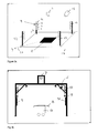
- Fig. 2a indicates how the total surface 8 which is intended to be analyzed is placed in or near the centre of a measuring system.
- four arrays 9, 10, 11, 12 are provided.
- a first array 9 has four flash lamps 2, 3, 13, 14 which are positioned on different vertical levels in a vertical row, i.e. in a row which is substantially perpendicular to an imaginary reference plane along which the surface 8 is oriented.
- the remaining arrays 10, 11, 12 are arranged in a similar manner as the first array 9.
- the four arrays 9, 10, 11, 12 are located in the four corners of a square, so that the total surface 8 can be illuminated from different directions and height angles ⁇ .
- the positions of these vertically oriented lamp arrays 9, 10, 11, 12 will be described later.
- the use of flash lamps makes it possible to operate the measuring system in daylight.
- a pattern generator 15 may also be used for obtaining initial height values, which will be described later. There are alternative methods of obtaining said initial height values, and using any of those methods, the pattern generator 15 will not be needed.
- a side view of the system set-up is shown in Fig. 2b, in which the total surface 8 that is intended to be examined is placed on a carriage 16. As shown in Fig.
- a supply box 17 and power meter 18 are also connected to the system.
- the supply box 17 constitutes an interface between the arrays 9, 10, 11, 12 of flash lamps and a control unit (not shown), which is computer-based and preferably in the form of a PC type computer.
- the supply box 17 is also adapted so as to deliver correct power to the flash lamps.
- the power meter 18 is adapted to measure the flash lamp power from the lamp arrays 9, 10, 11, 12. Accurate values of the flash lamp powers are needed for the evaluation of measurements in the control unit.
- each partial surface 1 with its slope ⁇ is illuminated from different angles. More precisely, a first angle ⁇ 1 corresponds to a first lamp 2 (see Fig. 3), a second angle ⁇ 2 corresponds to a second lamp 3, a third angle ⁇ 3 corresponds to a third lamp 13 and a fourth angle ⁇ 4 corresponds to a fourth lamp 14.
- One image is collected for every angle, i.e. one image is registered for each lamp 2, 3, 13, 14.
- every partial surface 1 preferably corresponds to a pixel of the digital camera 7. Then, for every pixel of the digital camera 7, the image intensity P as a function of ⁇ is collected and stored.
- the intensity P as a function of the angle of incidence ⁇ may be shown by means of a graph, see Fig. 4a.
- the measured values are then, for every pixel/partial surface 1, extrapolated to zero intensity P, where there is no reflection at all.
- the obtained value of the angle of incidence at zero image intensity P is denoted with reference numeral ⁇ 0 in Fig. 4a. It is important to note that this "zero value" ⁇ 0 of the angle of incidence equals the slope value ⁇ , since an imaginary lamp that is placed at an angle ⁇ with respect to the reference level 4 would result in no reflected light.
- One value of ⁇ is thus collected for every individual pixel/partial surface 1 for one vertical array of lamps 9, 10, 11, 12. This procedure gives the surface slope value ⁇ in the direction from the actual partial surface 1 to the lamp position. This information is extracted from the registered digital images for every individual pixel, where one image has been registered for each lamp.
- FIG. 2a an embodiment is shown having in total four arrays of lamps, as indicated by means of reference numerals 9, 10, 11, 12.
- a first array 9 and a second array 10 are positioned in such a way that they illuminate the surface substantially along an x-axis 19, whereas a third array 11 and a fourth array 12 are positioned in such a way that they illuminate said surface substantially along a y-axis 20.
- the result of this is that the slope values in the x- and y-directions ⁇ x (x,y) and ⁇ y (x,y) can be calculated for every individual image pixel.
- the surface slope values ⁇ is obtained in more than one horizontal direction (i.e. four distinct directions according to the described embodiment), and thus the slopes values in the x- and y-directions ⁇ x (x,y) and ⁇ y (x,y), respectively, can be calculated for every individual image pixel/partial surface 1. This principle is also indicated in Fig. 5.
- P m constb ⁇ sin( ⁇ - ⁇ ), see Fig. 4a.
- ⁇ is a constant for each pixel that is evaluated.
- the angle ⁇ changes from pixel to pixel, which does not affect the measurements, as they are relative measurements.
- Fig. 4b shows the manner in which the partial surface becomes reflecting for small angles ⁇ .
- a lower light intensity is detected by means of the camera 7, since the incoming light is reflected in a less diffuse way. Due to the fact that a higher light intensity generally is detected by the camera 7 when the reflection is more diffuse, the detected intensity is lower for the small angles ⁇ where the surface becomes reflecting.
- the extrapolation to zero intensity can be done even if the function P versus ⁇ is non-linear, as mentioned above with reference to Figs. 4b and 4c.
- the extrapolation algorithm can use an already known non-linear extrapolation function.
- the scattering behaviour may be previously known by means of, for example, studies of a special kind of material that is used frequently.
- the surface slopes in the x- and y-direction can be calculated.
- ⁇ x and ⁇ y are calculated for every image pixel (x, y).
- Every image pixel is to be given an initial height value.
- This initial height value is supposed to be a start value for the iteration process, and the better the start value is, the less time consuming the iteration becomes.
- This initial height value may be acquired by means of the pattern generator 13, the camera 7 and triangulating technique, as described in WO 01/79404 A1. Also, the flash lamps 2, 3, 13 ,1 4 may be used.
- a first method using the flash lamps 2, 3, 13 ,14 to acquire the initial height value needs at least two substantially opposing arrays of lamps 7, 8; 9, 10, as shown in Fig. 2a.
- the slope value ⁇ for a partial surface 1 is zero.
- the P versus ⁇ relationship can be obtained and extrapolated to zero intensity according to what has been described above.
- an estimation of the height for the imaginary lamp, that would have resulted in the angle of incidence ⁇ 0 that equals ⁇ can be carried out.
- This method is repeated for every partial surface 1, i.e. for every pixel in a digital image registered by the digital camera 7.
- a second method using the flash lamps is to use the iteration process described below as a pre-processing stage in order to acquire initial height values.
- a more rough method is to solely guess an initial height value.
- a height correction value corr(x,y) is therefore calculated for every pixel as the mean height difference between the edges of the partial surface/pixel 1 and its four neighbours 17, 16, 17, 18.
- the iteration process is executed as described in the following.
- the procedure above can first be carried out on larger surface elements consisting of e.g. 64x64 pixels. This gives initial height values for iteration with 32x32 pixel elements and so on.
- the number of lamps 2, 3, 13, 14 in every vertical lamp array 9, 10, 11, 12 may vary from two and more, and the number of arrays may also vary within the scope of the invention.
- the reflections that are referred to, are normally in the form of diffuse reflections.
- the invention is not limited to what has been described above, but may be varied freely within the scope of the appended claims.
- at least one vertical array of lamps with at least two lamps at each array is used for executing the present invention.
- the lamps used may for example be constituted by any sufficient light source.
Landscapes
- Physics & Mathematics (AREA)
- General Physics & Mathematics (AREA)
- General Health & Medical Sciences (AREA)
- Chemical & Material Sciences (AREA)
- Analytical Chemistry (AREA)
- Biochemistry (AREA)
- Life Sciences & Earth Sciences (AREA)
- Health & Medical Sciences (AREA)
- Immunology (AREA)
- Pathology (AREA)
- Engineering & Computer Science (AREA)
- Computer Vision & Pattern Recognition (AREA)
- Signal Processing (AREA)
- Length Measuring Devices By Optical Means (AREA)
- Investigating Materials By The Use Of Optical Means Adapted For Particular Applications (AREA)
Priority Applications (2)
| Application Number | Priority Date | Filing Date | Title |
|---|---|---|---|
| EP02445116A EP1400802A1 (de) | 2002-09-23 | 2002-09-23 | Verfahren und Vorrichtung zur Erfassung und Evaluierung von Oberflächenunebenheiten |
| US10/669,179 US20040125986A1 (en) | 2002-09-23 | 2003-09-23 | Method and system for detecting and evaluating surface irregularities |
Applications Claiming Priority (1)
| Application Number | Priority Date | Filing Date | Title |
|---|---|---|---|
| EP02445116A EP1400802A1 (de) | 2002-09-23 | 2002-09-23 | Verfahren und Vorrichtung zur Erfassung und Evaluierung von Oberflächenunebenheiten |
Publications (1)
| Publication Number | Publication Date |
|---|---|
| EP1400802A1 true EP1400802A1 (de) | 2004-03-24 |
Family
ID=31897016
Family Applications (1)
| Application Number | Title | Priority Date | Filing Date |
|---|---|---|---|
| EP02445116A Withdrawn EP1400802A1 (de) | 2002-09-23 | 2002-09-23 | Verfahren und Vorrichtung zur Erfassung und Evaluierung von Oberflächenunebenheiten |
Country Status (2)
| Country | Link |
|---|---|
| US (1) | US20040125986A1 (de) |
| EP (1) | EP1400802A1 (de) |
Cited By (1)
| Publication number | Priority date | Publication date | Assignee | Title |
|---|---|---|---|---|
| EP1921442A1 (de) * | 2006-11-10 | 2008-05-14 | Peugeot Citroen Automobiles SA | Verfahren und Anlage zur Qualitätskontrolle von Teilen |
Families Citing this family (4)
| Publication number | Priority date | Publication date | Assignee | Title |
|---|---|---|---|---|
| US9066028B1 (en) * | 2010-01-08 | 2015-06-23 | The United States Of America As Represented By The Administator Of The National Aeronautics And Space Administration | Methods and systems for measurement and estimation of normalized contrast in infrared thermography |
| JP6287301B2 (ja) * | 2014-02-13 | 2018-03-07 | アイシン精機株式会社 | 欠陥判定装置及び欠陥判定方法 |
| CN109405770B (zh) * | 2018-11-02 | 2020-12-25 | 上海华力微电子有限公司 | 一种通过光阻膜厚监控涂胶显影机台涂胶槽水平程度的方法 |
| JPWO2023218899A1 (de) * | 2022-05-13 | 2023-11-16 |
Citations (5)
| Publication number | Priority date | Publication date | Assignee | Title |
|---|---|---|---|---|
| US4988202A (en) * | 1989-06-28 | 1991-01-29 | Westinghouse Electric Corp. | Solder joint inspection system and method |
| DE4032327A1 (de) * | 1990-10-11 | 1992-04-16 | Abos Automation Bildverarbeitu | Verfahren und vorrichtung zur automatisierten ueberwachung der herstellung von halbleiterbauteilen |
| US5991039A (en) * | 1996-11-27 | 1999-11-23 | Matsushita Electronic Industrial Co., Ltd. | Electric component monitoring device and electronic component monitoring method |
| US20010005264A1 (en) * | 1999-05-05 | 2001-06-28 | Slemon Charles S. | Linked cameras and processors for imaging system |
| WO2001059404A1 (en) * | 2000-02-09 | 2001-08-16 | Volvo Personvagnar Ab | Arrangement and method for measuring surface irregularities at an object |
Family Cites Families (9)
| Publication number | Priority date | Publication date | Assignee | Title |
|---|---|---|---|---|
| US4695163A (en) * | 1985-06-17 | 1987-09-22 | Schachar Ronald A | Method and apparatus for determining surface shapes using reflected laser light |
| EP0359554B1 (de) * | 1988-09-16 | 1994-11-17 | Fujitsu Limited | System zum Detektieren eines biologischen Gegenstandes und dieses System verwendendes Fingerabdruckvergleichssystem |
| US5757474A (en) * | 1993-05-10 | 1998-05-26 | Midwest Research Institute | System for characterizing semiconductor materials and photovoltaic devices through calibration |
| US6271916B1 (en) * | 1994-03-24 | 2001-08-07 | Kla-Tencor Corporation | Process and assembly for non-destructive surface inspections |
| WO1995035506A2 (en) * | 1994-06-17 | 1995-12-28 | Kensington Laboratories, Inc. | Scribe mark reader |
| JP3509377B2 (ja) * | 1996-04-12 | 2004-03-22 | 株式会社ニコン | 曲率測定装置 |
| AU3991799A (en) * | 1998-05-14 | 1999-11-29 | Metacreations Corporation | Structured-light, triangulation-based three-dimensional digitizer |
| SE9900276L (sv) * | 1999-01-28 | 2000-01-10 | Skogsind Tekn Foskningsinst | Topografisk bestämning av en av infallande ljus belyst yta |
| US6552783B1 (en) * | 2000-06-28 | 2003-04-22 | Teradyne, Inc. | Optical system |
-
2002
- 2002-09-23 EP EP02445116A patent/EP1400802A1/de not_active Withdrawn
-
2003
- 2003-09-23 US US10/669,179 patent/US20040125986A1/en not_active Abandoned
Patent Citations (5)
| Publication number | Priority date | Publication date | Assignee | Title |
|---|---|---|---|---|
| US4988202A (en) * | 1989-06-28 | 1991-01-29 | Westinghouse Electric Corp. | Solder joint inspection system and method |
| DE4032327A1 (de) * | 1990-10-11 | 1992-04-16 | Abos Automation Bildverarbeitu | Verfahren und vorrichtung zur automatisierten ueberwachung der herstellung von halbleiterbauteilen |
| US5991039A (en) * | 1996-11-27 | 1999-11-23 | Matsushita Electronic Industrial Co., Ltd. | Electric component monitoring device and electronic component monitoring method |
| US20010005264A1 (en) * | 1999-05-05 | 2001-06-28 | Slemon Charles S. | Linked cameras and processors for imaging system |
| WO2001059404A1 (en) * | 2000-02-09 | 2001-08-16 | Volvo Personvagnar Ab | Arrangement and method for measuring surface irregularities at an object |
Cited By (2)
| Publication number | Priority date | Publication date | Assignee | Title |
|---|---|---|---|---|
| EP1921442A1 (de) * | 2006-11-10 | 2008-05-14 | Peugeot Citroen Automobiles SA | Verfahren und Anlage zur Qualitätskontrolle von Teilen |
| FR2908514A1 (fr) * | 2006-11-10 | 2008-05-16 | Peugeot Citroen Automobiles Sa | Procede et installation de controle de la qualite de pieces |
Also Published As
| Publication number | Publication date |
|---|---|
| US20040125986A1 (en) | 2004-07-01 |
Similar Documents
| Publication | Publication Date | Title |
|---|---|---|
| US8107089B2 (en) | Method and measuring device for measuring translation of surface | |
| JP3411829B2 (ja) | 表面形状の評価方法および評価装置 | |
| JP2012021781A (ja) | 表面形状の評価方法および評価装置 | |
| US20080175466A1 (en) | Inspection apparatus and inspection method | |
| CN104568781A (zh) | 一种光柱镭射纸张颜色和光柱质量自动检测和评价方法 | |
| US8184282B2 (en) | Method and system for defect detection using transmissive bright field illumination and transmissive dark field illumination | |
| US8433102B2 (en) | Surface roughness inspection system | |
| JP2012127675A (ja) | 表面形状の評価方法および評価装置 | |
| EP1400802A1 (de) | Verfahren und Vorrichtung zur Erfassung und Evaluierung von Oberflächenunebenheiten | |
| CN113670775B (zh) | 用于分析样品的表面与液体之间相互作用的方法和设备 | |
| US20130162816A1 (en) | Device for measuring the shape of a mirror or of a specular surface | |
| JP4630945B1 (ja) | 欠陥検査装置 | |
| KR102868765B1 (ko) | 미니 엘이디 장착 검사 방법 | |
| JP4597946B2 (ja) | 端部傾斜角測定方法、起伏を有する被検査物の検査方法および検査装置 | |
| JPH0629705B2 (ja) | 板状体の歪検査方法 | |
| KR101590552B1 (ko) | 곡선형 스프링 형상 검사 방법 | |
| JPH10307011A (ja) | 表面検査方法および表面検査装置 | |
| JP3661466B2 (ja) | 塗装ムラ検査装置および方法 | |
| JP7392582B2 (ja) | 検査システムおよび検査方法 | |
| JP2006003168A (ja) | 表面形状の測定方法およびその装置 | |
| KR20230174800A (ko) | 표시 패널 검사 장치 및 표시 패널 표면 검사 방법 | |
| JP2001349714A (ja) | メッシュ状パターンの均一性評価方法 | |
| JP3711892B2 (ja) | 3次元表面形状測定方法 | |
| JP2007333608A (ja) | シートにおける凹凸状欠点の検査装置および検査方法 | |
| JP2982471B2 (ja) | 塗装面性状検査装置 |
Legal Events
| Date | Code | Title | Description |
|---|---|---|---|
| PUAI | Public reference made under article 153(3) epc to a published international application that has entered the european phase |
Free format text: ORIGINAL CODE: 0009012 |
|
| AK | Designated contracting states |
Kind code of ref document: A1 Designated state(s): AT BE BG CH CY CZ DE DK EE ES FI FR GB GR IE IT LI LU MC NL PT SE SK TR |
|
| AX | Request for extension of the european patent |
Extension state: AL LT LV MK RO SI |
|
| 17P | Request for examination filed |
Effective date: 20040907 |
|
| AKX | Designation fees paid |
Designated state(s): DE GB SE |
|
| 17Q | First examination report despatched |
Effective date: 20070509 |
|
| RAP1 | Party data changed (applicant data changed or rights of an application transferred) |
Owner name: VOLVO CAR CORPORATION |
|
| STAA | Information on the status of an ep patent application or granted ep patent |
Free format text: STATUS: THE APPLICATION IS DEEMED TO BE WITHDRAWN |
|
| 18D | Application deemed to be withdrawn |
Effective date: 20120403 |