EP1400824A2 - Optische Fasermatrixanordnung mit Einstellschicht und Vorrichtung zur Herstellung der Fasermatrixanordnung - Google Patents
Optische Fasermatrixanordnung mit Einstellschicht und Vorrichtung zur Herstellung der Fasermatrixanordnung Download PDFInfo
- Publication number
- EP1400824A2 EP1400824A2 EP03021246A EP03021246A EP1400824A2 EP 1400824 A2 EP1400824 A2 EP 1400824A2 EP 03021246 A EP03021246 A EP 03021246A EP 03021246 A EP03021246 A EP 03021246A EP 1400824 A2 EP1400824 A2 EP 1400824A2
- Authority
- EP
- European Patent Office
- Prior art keywords
- optical
- fiber
- plate member
- fiber bare
- bare fibers
- Prior art date
- Legal status (The legal status is an assumption and is not a legal conclusion. Google has not performed a legal analysis and makes no representation as to the accuracy of the status listed.)
- Withdrawn
Links
Images


Classifications
-
- G—PHYSICS
- G02—OPTICS
- G02B—OPTICAL ELEMENTS, SYSTEMS OR APPARATUS
- G02B6/00—Light guides; Structural details of arrangements comprising light guides and other optical elements, e.g. couplings
- G02B6/24—Coupling light guides
- G02B6/36—Mechanical coupling means
- G02B6/3628—Mechanical coupling means for mounting fibres to supporting carriers
- G02B6/3632—Mechanical coupling means for mounting fibres to supporting carriers characterised by the cross-sectional shape of the mechanical coupling means
- G02B6/3636—Mechanical coupling means for mounting fibres to supporting carriers characterised by the cross-sectional shape of the mechanical coupling means the mechanical coupling means being grooves
-
- G—PHYSICS
- G02—OPTICS
- G02B—OPTICAL ELEMENTS, SYSTEMS OR APPARATUS
- G02B6/00—Light guides; Structural details of arrangements comprising light guides and other optical elements, e.g. couplings
- G02B6/24—Coupling light guides
- G02B6/36—Mechanical coupling means
- G02B6/3628—Mechanical coupling means for mounting fibres to supporting carriers
- G02B6/3648—Supporting carriers of a microbench type, i.e. with micromachined additional mechanical structures
- G02B6/3652—Supporting carriers of a microbench type, i.e. with micromachined additional mechanical structures the additional structures being prepositioning mounting areas, allowing only movement in one dimension, e.g. grooves, trenches or vias in the microbench surface, i.e. self aligning supporting carriers
-
- G—PHYSICS
- G02—OPTICS
- G02B—OPTICAL ELEMENTS, SYSTEMS OR APPARATUS
- G02B6/00—Light guides; Structural details of arrangements comprising light guides and other optical elements, e.g. couplings
- G02B6/24—Coupling light guides
- G02B6/26—Optical coupling means
- G02B6/30—Optical coupling means for use between fibre and thin-film device
-
- G—PHYSICS
- G02—OPTICS
- G02B—OPTICAL ELEMENTS, SYSTEMS OR APPARATUS
- G02B6/00—Light guides; Structural details of arrangements comprising light guides and other optical elements, e.g. couplings
- G02B6/24—Coupling light guides
- G02B6/36—Mechanical coupling means
- G02B6/38—Mechanical coupling means having fibre to fibre mating means
- G02B6/3807—Dismountable connectors, i.e. comprising plugs
- G02B6/3873—Connectors using guide surfaces for aligning ferrule ends, e.g. tubes, sleeves, V-grooves, rods, pins, balls
- G02B6/3885—Multicore or multichannel optical connectors, i.e. one single ferrule containing more than one fibre, e.g. ribbon type
Definitions
- This invention relates to an optical fiber array comprising a plurality of optical-fiber bare fibers which are disposed in alignment between two opposing plate members and are optically connected to connection elements (e.g., optical fiber lines, optical waveguide lines or optical elements on optical circuit boards) in an end-to-end facing arrangement with each other. More particularly, this invention relates to an optical fiber array which facilitates the optical and mechanical coupling of the bare fibers and the connection elements, and also relates to a method for manufacturing the same.
- connection elements e.g., optical fiber lines, optical waveguide lines or optical elements on optical circuit boards
- the alignment intervals between optical-fiber bare fibers are set with high accuracy so that positional matching and optical coupling can be facilitated with ease in relation to the optical fiber lines, optical wave guide lines or the like on optical circuit boards arranged at corresponding alignment intervals.
- optical-fiber bare fiber guide members for accurately setting the alignment intervals between optical-fiber bare fibers are provided as structural members of these optical fiber arrays.
- the V-groove member a as shown in Fig. 8A is conventionally known as an optical-fiber bare fiber guide member.
- the above V-groove member a is so configured that a plurality of grooves with substantially V-shaped cross sections (V grooves) a1 are formed lengthwise on its one side. Then, as shown in Fig. 8B, optical-fiber bare fibers c are respectively placed in the V grooves a1 of the V-groove member a. The optical-fiber bare fibers c are secured in place by the two lateral inclined planes of the V grooves a1, and the fixing positions of these optical-fiber bare fibers c are set, by downward pressure from a presser plate d on the upper part.
- a plurality of optical-fiber bare fibers c can be aligned at regular intervals by forming a plurality of identically sized V grooves a1 at regular intervals.
- An optical fiber array e configured as shown in Fig. 8C is obtained by filling the gaps between the optical-fiber bare fibers c (uncovered optical fibers themselves having been stripped of their outer envelopes, i.e., fibers each constituted of a core and a cladding are referred to as "optical-fiber bare fibers"; in a narrow sense, this term applies to portions uncovered by stripping optical-fiber fiber ribbons of their tip outer envelopes), the V-groove member a and the presser plate d with an adhesive and allowing this adhesive to solidify (see Japanese Patent Applications Laid-open No. 5-307129, No. 11-242127, No. 11-326704, No. 2000-275465 and No. 2000-329971).
- the optical-fiber bare fiber guide members such as the V-groove member a are required to have high dimensional accuracy, and hence the optical-fiber bare fiber guide members involve a high manufacturing cost.
- optical fiber arrays are provided with the above optical-fiber bare fiber guide members set in as structural members, and hence there has been a problem that the cost of such optical fiber arrays is also proportionally higher.
- this manufacturing method entails, as shown in Fig. 9A, installing an optical-fiber fiber ribbon alignment guide g provided on its top surface with a plurality of V grooves formed at an equal pitch, an optical-fiber bare fiber alignment guide h provided on its top surface with a plurality of V grooves formed at an equal pitch (see Fig. 10), and a presser i having trapezoid projections that fit into the V grooves of the optical-fiber bare fiber alignment guide h.
- optical-fiber fiber ribbons k portions uncovered by stripping optical-fiber cables j of their jackets j1, i.e., portions covered with ribbon material k1 for fiber ribbons are referred to as "optical-fiber fiber ribbons" are inserted into the V grooves of the optical-fiber fiber ribbon alignment guide g to support these optical-fiber fiber ribbons k in a parallel formation.
- optical-fiber bare fibers m are inserted into the V grooves of the optical-fiber bare fiber alignment guide h to support the optical-fiber bare fibers m in a parallel formation.
- the presser i is placed on the optical-fiber bare fiber alignment guide h to prevent the optical-fiber bare fibers m from shifting upward.
- the external peripheral surfaces of the optical-fiber bare fibers and optical-fiber fiber ribbons k are coated with an adhesive n.
- a bottom plate r (see Fig. 11) is so set that a flat surface p thereof is disposed underneath the optical-fiber bare fibers m and that an angular groove q is disposed underneath the optical-fiber fiber ribbons k.
- a top plate s (see Fig. 11) is also so set that a flat surface p thereof is disposed above the optical-fiber bare fibers m and that an angular groove q is disposed above the optical-fiber fiber ribbons k.
- the optical-fiber bare fibers m are sandwiched between the top plate s and the bottom plate r, in the state of which the adhesive n is allowed to harden to bond the top plate s and the bottom plate r together.
- the adhesive n and optical-fiber bare fibers m extending from the integrated top plate s and bottom plate r are removed to obtain an optical fiber array t such as that shown in Fig. 9C.
- the optical-fiber bare fibers m are aligned with the aid of an optical-fiber fiber ribbon alignment guide g, an optical-fiber bare fiber alignment guide h and a presser i, and the completed optical fiber array t is devoid of any optical-fiber bare fiber guide members, making it possible to markedly lower the manufacturing costs of such optical fiber arrays.
- This manufacturing method has had a problem that the optical-fiber bare fibers m can not be aligned with high accuracy for the reasons stated below, and has not been a method in which manufacturing costs can be lowered without reducing the accuracy of alignment intervals between the optical-fiber bare fibers.
- the optical-fiber bare fibers m sandwiched between the optical-fiber bare fiber alignment guide h and the presser i as shown in Fig. 9A (however, as shown in Fig. 9B, these portions correspond to the portions of the optical-fiber bare fibers m that extend from the integrated top plate s and bottom plate r, and are portions removed together with the uncovered adhesive in the manner described above).
- the optical-fiber bare fibers m may loose their tension as they extend from the optical-fiber bare fiber alignment guide h toward the optical-fiber fiber ribbon alignment guide g, making it difficult to align the optical-fiber bare fibers m at these portions with high accuracy.
- applying the adhesive n to the external peripheral surfaces of the optical-fiber bare fibers m as shown in Fig. 9A may cause the optical-fiber bare fibers m to move close to each other as a result of the surface tension of the adhesive n.
- the top plate s or the bottom plate r is brought into contact from above or below with the optical-fiber bare fibers m coated with the adhesive n as shown in Fig. 9B, the optical-fiber bare fibers m and the top plate s or bottom plate r are brought closer to each other by the surface tension of the adhesive n. These may cause the interval between the optical-fiber bare fibers m to vary, making accurate alignment of the optical-fiber bare fibers m difficult to achieve.
- the top plate s or the bottom plate r may cause the optical-fiber bare fibers m to shift their positions because of any slight differences in contact pressure on the optical-fiber bare fibers m between the top plate s and the bottom plate r, making accurate alignment of the optical-fiber bare fibers m difficult to achieve.
- the present inventor has already proposed an optical fiber array manufacturing method which can lower the manufacturing cost by saving the setting-in of the expensive optical-fiber bare fiber guide member without lowering the accuracy of alignment intervals in the optical-fiber bare fibers (see Japanese Patent Application Laid-open No. 2000-193844, corresponding to U.S. Patent No. 6,368,441).
- optical-fiber bare fibers m are held in V grooves h1 of an optical-fiber bare fiber alignment guide h so that they are aligned one by one.
- a plate member A provided with an adhesive layer (not shown) is brought into contact with the respective optical-fiber bare fibers m aligned by the optical-fiber bare fiber alignment guide h, and these are pressed on the back side of the plate member A by a transparent pressing means Z to keep the optical-fiber bare fibers m sandwiched between the optical-fiber bare fiber alignment guide h and the plate member A, in the state of which the respective optical-fiber bare fibers m are fastened onto the plate member A through the adhesive layer. Thereafter, the optical-fiber bare fibers m are separated from the optical-fiber bare fiber alignment guide h.
- a plate member B is superposingly fitted to the optical-fiber bare fibers m fastened onto the plate member A. Thereafter, an uncured resin material fed onto the plate member B is made to cure into a cured product and the plate member A is unified with the plate member B.
- optical-fiber bare fibers m extending outward from ends of the unified plate member A and plate member B are removed.
- this optical fiber array is completed.
- the optical-fiber bare fibers m held in the region where they have been aligned by the optical-fiber bare fiber alignment guide h are mounted between the plate member A and the plate member B.
- the alignment intervals in the optical-fiber bare fibers can be set with high accuracy.
- the thickness dimension of the plate member A and that of the plate member B are uniformly equal over the length in the direction of alignment of the optical-fiber bare fibers m.
- the flat surface of the plate member B on the side opposite to the side on which the optical-fiber bare fibers m are held serves as a disposition standard surface B1 when the array is set in
- the thickness dimension of the plate member B may come non-uniform as shown in Fig. 13 (d1 differs from d2).
- the distance from central points of the respective optical-fiber bare fibers m to the disposition standard surface B1 may vary to make it impossible to adjust to a desired preset distance H the distance from the disposition standard surface B1 to the central points of the respective optical-fiber bare fibers m. There has been such a problem.
- single-mode optical fibers mounted to an optical fiber array and light rays guided through optical waveguide paths have a diameter of about 10 ⁇ m.
- the single-mode optical fibers and the optical waveguide paths are positionally deviated by 10 ⁇ m or more, their mutual conduction can not be ensured, so that any operation to make mutual positional adjustment that may make the intensity of guided light maximum can not be started. There has been such a problem.
- the thickness dimension of the plate member B conventionally used may vary in a width of 10 ⁇ m or more, the guided light can not be ensured however accurately the dimensions of optical guide paths are set. Hence, there has been the problem that any operation to make mutual positional adjustment that may make the intensity of guided light maximum can not be started.
- an object of the present invention is to provide an optical fiber array in which the distance from the disposition standard surface to the central points of the respective optical-fiber bare fibers can be adjusted to the preset distance H even when plate members having non-uniform thickness dimension are used, and to provide a method for manufacturing such an optical fiber array.
- the optical fiber array according to the present invention is an optical fiber array comprising a plurality of optical-fiber bare fibers which are disposed in alignment between two opposing plate members and are optically connected to connection elements in an end-to-end facing arrangement with each other, wherein; the optical-fiber bare fibers are disposed in contact with a flat surface of one plate member A, an adjustment layer formed of an adhesive is interposed between another plate member B and the plate member A, where a flat surface of the plate member B on its side opposite to the adjustment layer serves as a disposition standard surface when the array is set in; and the adjustment layer, which fulfills conditions of (dmax + r) ⁇ H where the desired preset distance from i) a central line of the optical-fiber bare fibers which is formed by connecting central points of end cross sections in the optical-fiber bare fibers disposed in alignment to ii) the disposition standard surface is represented by H, the maximum value of the thickness dimension in the plate member B by dmax, and the radius of the end cross sections of the respective optical-
- the optical fiber array manufacturing method according to the present invention is a method for manufacturing the aforesaid optical fiber array, the method comprising the steps of:
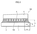
- an optical fiber array 100 is chiefly constituted of a pair of plate members, a plate member-A 2 and a plate member-B 1, a plurality of optical-fiber bare fibers 5 disposed in alignment between these plate member-A 2 and plate member-B 1, and an adjustment layer 7 likewise provided between the plate member-A 2 and the plate member-B 1 and formed of an adhesive 6 comprised of a mixture of a resin and an inorganic filler.
- the respective optical-fiber bare fibers 5 are disposed in contact with a flat surface of the plate member-A 2.
- the adjustment layer 7 is interposed between the plate member-B 1 and the plate member-A 1, where a flat surface of the plate member-B on its side opposite to the adjustment layer 7 serves as a disposition standard surface 3 when the array is set in.
- the adjustment layer which fulfills conditions of (dmax + r) ⁇ H where the desired preset distance from i) a central line of the optical-fiber bare fibers 5 which is formed by connecting central points of end cross sections in the optical-fiber bare fibers 5 disposed in alignment to ii) the disposition standard surface 3 is represented by H, the maximum value of the thickness dimension in the plate member-B 1 by dmax, and the radius of the end cross sections of the respective optical-fiber bare fibers 5 by r, compensates a deviation from the preset distance H that is caused by a non-uniformity in thickness dimension in the plate member-B 1, whereby the distance from the central points of the respective optical-fiber bare fibers 5 to the disposition standard surface 3 is set identical or substantially identical to the preset distance H.
- the central line which is formed by connecting central points of end cross sections in the optical-fiber bare fibers 5 is herein often simply called the central line.
- the horizontal distance W between one side (lateral surface) of at least one of the plate member-A 2 and the plate member-B 1 and the central point of an end cross section of an arbitrary optical-fiber bare fiber 5 is set to a desired preset value with high accuracy.
- the distance from the central points of the respective optical-fiber bare fibers 5 to the disposition standard surface 3 is set identical or substantially identical to the preset distance H, and also the horizontal distance W between one side (lateral surface) of the plate member-A 2 or plate member-B 1 and the arbitrary optical-fiber bare fiber 5 is set to the desired preset value with high accuracy.
- the optical fiber array has an advantage that it facilitates the optical and mechanical coupling with the connection elements such as optical waveguide paths disposed opposingly to this array.
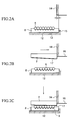
- an optical-fiber bare fiber alignment guide 8 having V grooves at its surface is placed on a vertical-position standard wall surface 13 of a plate member-B supporting means 12.
- One side (lateral surface) of this optical-fiber bare fiber alignment guide 8 is disposed being pressed against a horizontal-position standard wall surface 15 of the plate member-B supporting means 12.
- the respective V grooves of the optical-fiber bare fiber alignment guide 8 are arranged in an accurate horizontal position extending from the lateral surface of the optical-fiber bare fiber alignment guide 8 on its side pressed against the horizontal-position standard wall surface 15.
- the respective V grooves are arranged in an accurate horizontal position in respect to the horizontal-position standard wall surface 15.
- optical-fiber bare fibers 5 are respectively received in the V grooves so as to be held in alignment.
- a plate member-A 2 is carried on a plate member-A supporting means (not shown).
- the plate member-A 2 is also so carried that its one side (lateral surface) is pressed against a horizontal-position standard wall surface 14 which is part of the plate member-A supporting means.
- the horizontal distance ⁇ between the horizontal-position standard wall surface 14 and the horizontal-position standard wall surface 15 is kept set accurately at the desired value as shown in Fig. 2A.
- a thin fixing adhesive layer 17 is also formed on the plate member-A 2 on its side facing the optical-fiber bare fiber alignment guide 8.
- an ultraviolet-curable adhesive is used, for example.
- materials transparent to ultraviolet rays is used, for example.
- the plate member-A 2 is made to descend to bring its fixing adhesive layer 17 into contact with the optical-fiber bare fibers 5 aligned on the optical-fiber bare fiber alignment guide 8.
- the plate member-A 2 and plate member-A supporting means are irradiated by ultraviolet rays to make the latter ultraviolet rays transmitted through the former to cause the fixing adhesive layer 17 to cure, so that the optical-fiber bare fibers 5 are fixed to the plate member-A 2.
- a fixed member 10 consisting of the optical-fiber bare fibers 5 and the plate member-A 2 is made to ascend, and the optical-fiber bare fiber alignment guide 8 is removed from the plate member-B supporting means 12.
- the optical-fiber bare fiber alignment guide 8 the same one or a replica having the same size can repeatedly be used, and hence it is easy to always set to the desired constant value the horizontal distance between the horizontal-position standard wall surface 15 of the plate member-B supporting means 12 and the optical-fiber bare fibers 5.
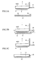
- the fixed member 10 consisting of the optical-fiber bare fibers 5 and the plate member-A 2 is made to descend to press the outer peripheral bottom surfaces of the optical-fiber bare fibers 5 against the vertical-position standard wall surface 13 of the plate member-B supporting means 12.
- the plate member-A supporting means may be controlled by means of a swing mechanism (not shown) so that the posture (relative disposition) of the fixed member 10 can freely be changed in the state the lateral surface of the plate member-A supporting means is in contact with the horizontal-position standard wall surface 14.
- the outer peripheral bottom surfaces of the optical-fiber bare fibers 5 can be made to extend accurately along the vertical-position standard wall surface 13 and can be made parallel to the vertical-position standard wall surface 13 (i.e., the central line of the optical-fiber bare fibers 5 is parallel to the vertical-position standard wall surface 13).
- the posture of the plate member-A supporting means and fixed member 10 is fixed by means of a chuck mechanism (not shown).
- the height h0 of a vertical-position standard wall surface 16 is recorded as a standard value of "zero" in the state the outer peripheral bottom surfaces of the optical-fiber bare fibers 5 are in contact with the vertical-position standard wall surface 13 (i.e., the vertical distance between the vertical-position standard wall surface 13 and the outer peripheral bottom surfaces of the optical-fiber bare fibers 5 kept in contact with the standard wall surface 13 is zero).
- a high-precision displacement measuring means as exemplified by a laser distance meter may be used.
- the fixed member 10 is made to ascend to a stated height in the state that the parallelism between the outer peripheral bottom surfaces of the optical-fiber bare fibers 5 and the vertical-position standard wall surface 13 (i.e., the parallelism between the central line of the optical-fiber bare fibers 5 and the vertical-position standard wall surface 13) is maintained, also that the horizontal distance ⁇ between the horizontal-position standard wall surface 14 and the horizontal-position standard wall surface 15 is kept constant, and still also that the lateral surface of the plate member-A 2 in the fixed member 10 is kept in contact with the horizontal-position standard wall surface 14.
- the plate member-B 1 is placed on the vertical-position standard wall surface 13 of the plate member-B supporting means 12.
- one side (lateral surface) of the plate member-B 1 is disposed being pressed against the horizontal-position standard wall surface 15 of the plate member-B supporting means 12.
- an adhesive 6 is fed to the top surface of the plate member-B 1 placed being pressed against the horizontal-position standard wall surface 15 of the plate member-B supporting means 12.
- an ultraviolet-curable adhesive is used, for example.
- the plate member-A supporting means is made to descend until the height of the vertical-position standard wall surface 16 comes to be h1, so that the state shown in Fig. 4B is brought about, in which the plate member-A 2, the plate member-B 1 and the optical-fiber bare fibers 5 have been joined together via the adhesive 6.
- the plate member-A 2 and plate member-A supporting means are irradiated by ultraviolet rays to make the latter ultraviolet rays transmitted through the former to cause the adhesive 6 to cure, so that the plate member-A 2, the plate member-B 1 and the optical-fiber bare fibers 5 are integrated.
- the optical fiber array 100 shown in Fig. 1 is completed.
- the fixed member 10 consisting of the optical-fiber bare fibers 5 and the plate member-A 2 is made to descend to press the outer peripheral bottom surfaces of the optical-fiber bare fibers 5 against the vertical-position standard wall surface 13 of the plate member-B supporting means 12.
- the outer peripheral bottom surfaces of the optical-fiber bare fibers 5 extend accurately along the vertical-position standard wall surface 13 to come parallel to the vertical-position standard wall surface 13.
- each optical-fiber bare fiber 5 Since the diameter of each optical-fiber bare fiber 5 is set to a constant value with high accuracy of ⁇ 0.5 ⁇ m or less, the central line of the optical-fiber bare fibers 5 which is formed by connecting central points of end cross sections in the respective optical-fiber bare fibers 5 is also set parallel to the vertical-position standard wall surface 13.
- the plate member-B 1 Since, in the state this parallelism is maintained, the plate member-B 1 is placed on the vertical-position standard wall surface 13 of the plate member-B supporting means 12 to complete the integration of the plate member-B 1 and the fixed member 10 consisting of the optical-fiber bare fibers 5 and the plate member-A 2, as shown in Fig. 4B the central line of the optical-fiber bare fibers 5 and the disposition standard surface 3 of the plate member-B 1 can be set accurately parallel.
- the adjustment layer 7 interposed between the central line of the optical-fiber bare fibers 5 and the plate member-B 1 compensates a deviation from the preset distance H that is caused by this non-uniformity in thickness dimension, whereby the distance from the central points of the respective optical-fiber bare fibers 5 to the disposition standard surface 3 is set identical or substantially identical to the preset distance H.
- the height h1 of the vertical-position standard wall surface 16 as shown in Fig. 4A is also adjusted so that the distance from the central line of the optical-fiber bare fibers 5 to the disposition standard surface 3 can be adjusted to the desired preset distance H.
- the thickness dimension of the plate member-B 1 does not come up to the preset distance H from the central line of the optical-fiber bare fibers 5 to the disposition standard surface 3.
- the absolute value of the thickness dimension also varies between different plate members-B 1.
- the adjustment layer interposed between the optical-fiber bare fibers 5 and the plate member-B 1 can arbitrarily change the thickness dimension in virtue of the flow of the adhesive (resin) when it is put between them before its curing.
- the high-precision displacement measuring means as exemplified by a laser distance meter may be used to measure the height of the vertical-position standard wall surface 16, and hence the preset distance H can be adjusted in units of micrometers. Even when any error of mechanical registration of holding mechanisms in the respective members is taken into account, it is well easy to set the preset distance H with an accuracy of ⁇ 5 ⁇ m or less.
- the horizontal position of the respective V grooves of the optical-fiber bare fiber alignment guide 8 is accurately defined in respect to the horizontal-position standard wall surface 15 as shown in Fig. 2A.
- the horizontal position of rows of the optical-fiber bare fibers 5 i.e., the horizontal position of the central line of the optical-fiber bare fibers 5
- the horizontal position of the plate member-A 2 is accurately defined in respect to the horizontal-position standard wall surface 14 as shown in Fig. 2B
- the horizontal distance ⁇ between the horizontal-position standard wall surface 14 and the horizontal-position standard wall surface 15 each other is kept at a constant value as shown in Fig. 2C.
- the horizontal distance W (see Fig. 1) between any central points of end cross sections in the optical-fiber bare fibers 5 and the lateral surface of the plate member-B 1 is also set with high accuracy.
- the optical-fiber bare fiber alignment guide 8 is placed on the vertical-position standard wall surface 13 of the plate member-B supporting means 12. One side (lateral surface) of the optical-fiber bare fiber alignment guide 8 is disposed being pressed against the horizontal-position standard wall surface 15 of the plate member-B supporting means 12.
- the central position of the V groove at the right-most end as viewed in the drawing in the optical-fiber bare fiber alignment guide 8 is set to be accurately 1,000 ⁇ m from the lateral surface of the optical-fiber bare fiber alignment guide 8 on its side pressed against the horizontal-position standard wall surface 15.
- the optical-fiber bare fibers 5 are respectively received in the V grooves so as to be held in alignment.
- optical-fiber bare fibers 5 each have a diameter of 125 ⁇ m.
- the plate member-A 2 is carried on the plate member-A supporting means (not shown).
- the plate member-A 2 is made of quartz glass, and has a thickness of 1,000 ⁇ m and a width of 3,500 ⁇ m.
- the plate member-A 2 is so carried that its one side (lateral surface) is pressed against the horizontal-position standard wall surface 14 which is part of the plate member-A supporting means.
- the horizontal distance ⁇ (see Fig. 2A) between the horizontal-position standard wall surface 14 and the horizontal-position standard wall surface 15 is set to be accurately 250 ⁇ m.
- the thin fixing adhesive layer 17 is also formed on the plate member-A 2 on its side facing the optical-fiber bare fiber alignment guide 8.
- the fixing adhesive layer 17 is formed of an ultraviolet-curable epoxy resin.
- the plate member-A supporting means is made of quartz glass, and is transparent to ultraviolet rays.
- the plate member-A 2 is made to descend to bring its fixing adhesive layer 17 into contact with the optical-fiber bare fibers 5 aligned on the optical-fiber bare fiber alignment guide 8.
- the plate member-A 2 and plate member-A supporting means are irradiated by ultraviolet rays to make the latter ultraviolet rays transmitted through the former to cause the fixing adhesive layer 17 to cure, so that the optical-fiber bare fibers 5 are fixed to the plate member-A 2.
- the fixed member 10 consisting of the optical-fiber bare fibers 5 and the plate member-A 2 is made to ascend, and the optical-fiber bare fiber alignment guide 8 is removed from the plate member-B supporting means 12.
- the optical-fiber bare fiber alignment guide 8 the same one is repeatedly used.
- the fixed member 10 is made to descend to press the outer peripheral bottom surfaces of the optical-fiber bare fibers 5 against the vertical-position standard wall surface 13 of the plate member-B supporting means 12.
- the plate member-A supporting means may be controlled by means of a swing mechanism (not shown) so that the posture (relative disposition) of the fixed member 10 can freely be changed in the state the lateral surface of the plate member-A supporting means in the fixed member 10 is in contact with the horizontal-position standard wall surface 14.
- the outer peripheral bottom surfaces of the optical-fiber bare fibers 5 can be made to extend accurately along the vertical-position standard wall surface 13 and can be made parallel to the vertical-position standard wall surface 13.
- the posture of the plate member-A supporting means and fixed member 10 is fixed by means of a chuck mechanism (not shown).
- the height h0 of the vertical-position standard wall surface 16 is reset to the standard value of "zero" in the state the outer peripheral bottom surfaces of the optical-fiber bare fibers 5 are in contact with the vertical-position standard wall surface 13 (i.e., the vertical distance between the vertical-position standard wall surface 13 and the outer peripheral bottom surfaces of the optical-fiber bare fibers 5 kept in contact with the standard wall surface 13 is zero).
- a laser distance meter is used to measure the height of the vertical-position standard wall surface 16.
- the fixed member 10 is made to ascend until the measured value of the height of the vertical-position standard wall surface 16 come to be 5,000 ⁇ m or more, in the state that the parallelism between the outer peripheral bottom surfaces of the optical-fiber bare fibers 5 and the vertical-position standard wall surface 13 (i.e., the parallelism between the central line of the optical-fiber bare fibers 5 and the vertical-position standard wall surface 13) is maintained, also that the horizontal distance ⁇ between the horizontal-position standard wall surface 14 and the horizontal-position standard wall surface 15 is kept constant, and still also that the lateral surface of the plate member-A 2 in the fixed member 10 is kept in contact with the horizontal-position standard wall surface 14.
- the plate member-B 1 is placed on the vertical-position standard wall surface 13 of the plate member-B supporting means 12.
- one side (lateral surface) of the plate member-B 1 is disposed being pressed against the horizontal-position standard wall surface 15 of the plate member-B supporting means 12.
- the plate member-B 1 is made of quartz glass, and has a non-uniformity of ⁇ 2 ⁇ m in a thickness of 950 ⁇ m and has a width of 4,000 ⁇ m.
- the adhesive 6 is fed to the top surface of the plate member-B 1.
- the adhesive 6 used is an ultraviolet-curable epoxy resin (trade name: NA3925; available from NTT-AT Co.) in which 25% by weight of a quartz filler has been mixed to control its cure shrinkage to 4% or less.
- the plate member-A supporting means is made to descend until the height h1 of the vertical-position standard wall surface 16 comes to be 1,000 ⁇ m, so that the state shown in Fig. 4B is brought about, in which the plate member-A 2, the plate member-B 1 and the optical-fiber bare fibers 5 have been joined together via the adhesive 6.
- the plate member-A 2 and plate member-A supporting means are irradiated by ultraviolet rays to make the latter ultraviolet rays transmitted through the former to cause the adhesive 6 to cure, so that the plate member-A 2, the plate member-B 1 and the optical-fiber bare fibers 5 are integrated.
- the optical fiber array 100 shown in Fig. 1 is completed.
- the thickness of the adjustment layer has decreased by 2 ⁇ m as a result of the cure shrinkage to come to be 48 ⁇ m.
- the preset distance H between the central line of the optical-fiber bare fibers 5 and the disposition standard surface 3 in the plate member-B 1 has come to be 1,060.5 ⁇ m.
- the thickness dimension of the plate member-B 1 varies as shown in Fig. 1, but such variation is cancelled or compensated by the variation of the adjustment layer 7 (in virtue of the flow of the adhesive before curing as described above) interposed between the rows of the optical-fiber bare fibers 5 and the plate member-B 1.
- the preset distance H between the rows of the optical-fiber bare fibers 5 and the disposition standard surface 3 in the plate member-B 1 is kept constant at 1,060.5 ⁇ m without regard to any spots in the plate member-B 1.
- the horizontal distance W between the central point of an end cross section of the right-most arbitrary optical-fiber bare fiber 5 and the lateral surface 4 of the plate member-B 1 is also set to 1,000 ⁇ m.
- the plate member-B 1 used this time was 960 ⁇ m in thickness, different from the previous thickness 950 ⁇ m.
- the plate member-A supporting means was made to descend until the height h1 of the vertical-position standard wall surface 16 came to be 1, 000 ⁇ m, so that an adjustment layer 7 of 40 ⁇ m in thickness was formed between the outer peripheral bottom surfaces of the optical-fiber bare fibers 5 and the top surface of the plate member-B 1.
- This adjustment layer 7 came to be 38.4 ⁇ m upon cure shrinkage.
- the preset distance H between the central line of the optical-fiber bare fibers 5 and the disposition standard surface 3 in the plate member-B 1 came to be 1,060.9 ⁇ m, showing a result corresponding with the previous case with high accuracy.
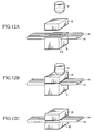
- the optical-fiber bare fiber alignment guide 8 is placed on the vertical-position standard wall surface 13 of the plate member-B supporting means 12, which is provided upside down in this Example.
- One side (lateral surface) of the optical-fiber bare fiber alignment guide 8 is disposed being pressed against the horizontal-position standard wall surface 15 of the plate member-B supporting means 12.
- the central position of the V groove at the right-most end as viewed in the drawing in the optical-fiber bare fiber alignment guide 8 is set to be accurately 1,000 ⁇ m from the lateral surface of the optical-fiber bare fiber alignment guide 8 on its side pressed against the horizontal-position standard wall surface 15.
- the optical-fiber bare fibers 5 are respectively received in the V grooves so as to be held in alignment.
- the V grooves of the optical-fiber bare fiber alignment guide 8 face downward as shown in Fig. 5A, where the optical-fiber bare fibers 5 can be received in alignment in the V grooves in virtue of rigidity the optical-fiber bare fibers 5 have (provided that the optical-fiber bare fibers 5 are fastened with a supporting means (not shown) on its base end side, i.e., on its optical-fiber fiber ribbon side).
- the optical-fiber bare fibers 5 each have a diameter of 125 ⁇ m.
- the plate member-A 2 is carried on a plate member-A supporting means 11.
- the plate member-A 2 is made of quartz glass, and has a thickness of 1,000 ⁇ m and a width of 3,500 ⁇ m.
- the plate member-A 2 is so carried that its one side (lateral surface) is pressed against the horizontal-position standard wall surface 14 of the plate member-A supporting means 11.
- the horizontal distance ⁇ (see Fig. 5A) between the horizontal-position standard wall surface 14 and the horizontal-position standard wall surface 15 is set to be accurately 250 ⁇ m.
- the thin fixing adhesive layer 17 is also formed on the plate member-A 2 on its side facing the optical-fiber bare fiber alignment guide 8.
- the fixing adhesive layer 17 is formed of an ultraviolet-curable epoxy resin.
- the plate member-A supporting means 11 is made of quartz glass, and is transparent to ultraviolet rays.
- the optical-fiber bare fiber alignment guide 8 is made to descend to bring the fixing adhesive layer 17 into contact with the optical-fiber bare fibers 5 aligned on the optical-fiber bare fiber alignment guide 8.
- the plate member-A 2 and plate member-A supporting means 11 are irradiated by ultraviolet rays to make the latter ultraviolet rays transmitted through the former to cause the fixing adhesive layer 17 to cure, so that the optical-fiber bare fibers 5 are fixed to the plate member-A 2 to come into the fixed member 10 consisting of the optical-fiber bare fibers 5 and the plate member-A 2.
- the plate member-B supporting means 12 is made to ascend, and the optical-fiber bare fiber alignment guide 8 is removed from the plate member-B supporting means 12.
- the optical-fiber bare fiber alignment guide 8 the same one is repeatedly used.
- the plate member-B supporting means 12 is made to descend to press the outer peripheral top surfaces of the optical-fiber bare fibers 5 against the vertical-position standard wall surface 13 of the plate member-B supporting means 12.
- the plate member-B supporting means 12 may be controlled by means of a swing mechanism (not shown) so that the inclination of the vertical-position standard wall surface 13 can freely be changed in the state the horizontal position of the horizontal-position standard wall surface 15 is kept unchanged.
- the vertical-position standard wall surface 13 can be made to extend accurately along the outer peripheral top surfaces of the optical-fiber bare fibers 5, and can be made parallel to the outer peripheral top surfaces of the optical-fiber bare fibers 5 (i.e., the central line of the optical-fiber bare fibers 5 and the vertical-position standard wall surface 13 are parallel to each other).
- the posture of the plate member-B supporting means 12 is fixed by means of a chuck mechanism (not shown).
- the height h0 of the vertical-position standard wall surface 16 is reset to the standard value of "zero" in the state the outer peripheral top surfaces of the optical-fiber bare fibers 5 are in contact with the vertical-position standard wall surface 13 (i.e., the vertical distance between the vertical-position standard wall surface 13 and the outer peripheral top surfaces of the optical-fiber bare fibers 5 kept in contact with the standard wall surface 13 is zero).
- a laser distance meter is used to measure the height of the vertical-position standard wall surface 16.
- the plate member-B supporting means 12 is made to ascend until the measured value of the height of the vertical-position standard wall surface 16 come to be 5,000 ⁇ m or more, in the state that the parallelism between the outer peripheral top surfaces of the optical-fiber bare fibers 5 fastened to the plate member-A 2 and the vertical-position standard wall surface 13 in the plate member-B supporting means 12 is maintained, also that the horizontal distance ⁇ between the horizontal-position standard wall surface 14 and the horizontal-position standard wall surface 15 is kept constant, and still also that the lateral surface of the plate member-A 2 in the fixed member 10 is kept in contact with the horizontal-position standard wall surface 14.
- the adhesive 6 is fed to the top surface of the plate member-A 2.
- the adhesive 6 used is an ultraviolet-curable epoxy resin (trade name: NA3925; available from NTT-AT Co.) in which 25% by weight of a spherical quartz filler has been mixed to control its cure shrinkage to 4% or less.
- the plate member-B 1 is placed on the vertical-position standard wall surface 13 of the plate member-B supporting means 12.
- one side (lateral surface) of the plate member-B 1 is disposed being pressed against the horizontal-position standard wall surface 15 of the plate member-B supporting means 12.
- the plate member-B 1 is made of quartz glass, and has a non-uniformity of ⁇ 2 ⁇ m in a thickness of 950 ⁇ m and has a width of 4,000 ⁇ m.
- the plate member-B supporting means 12 is made to descend until the height h1 of the vertical-position standard wall surface 16 comes to be 1,000 ⁇ m, so that the state shown in Fig. 7B is brought about, in which the plate member-A 2, the plate member-B 1 and the optical-fiber bare fibers 5 have been joined together via the adhesive 6.
- the adjustment layer 7 which involves the non-uniformity of ⁇ 2 ⁇ m in thickness in respect to a thickness center value of 50 ⁇ m, is interposed between the outer peripheral top surfaces of the optical-fiber bare fibers 5 and the top surface of the plate member-B 1.
- the plate member-A 2 and plate member-A supporting means 11 are irradiated by ultraviolet rays to make the latter ultraviolet rays transmitted through the former to cause the adhesive 6 to cure, so that the plate member-A 2, the plate member-B 1 and the optical-fiber bare fibers 5 are integrated.
- the thickness of the adjustment layer 7 has decreased by 2.5 ⁇ m as a result of the cure shrinkage to come to be 48 ⁇ m.
- the preset distance H between the central line of the optical-fiber bare fibers 5 (a straight line formed by connecting cross-sectional central points of the optical-fiber bare fibers 5) and the top surface of the plate member-B 1 (i.e., the disposition standard surface 3) has come to be 1,060.5 ⁇ m.
- the thickness dimension of the plate member-B 1 varies as shown in Fig. 7, but such variation is cancelled or compensated by the variation of the adjustment layer 7 (in virtue of the flow of the adhesive before curing as described above) interposed between the rows of the optical-fiber bare fibers 5 and the plate member-B 1.
- the preset distance H between the rows of the optical-fiber bare fibers 5 and the disposition standard surface 3 in the plate member-B 1 is kept constant at 1,060.5 ⁇ m without regard to any spots in the plate member-B 1.
- the horizontal distance W between the central point of an end cross section of the right-most arbitrary optical-fiber bare fiber 5 and the lateral surface 4 of the plate member-B 1 is also set to 1,000 ⁇ m.
- the plate member-B 1 used this time was 960 ⁇ m in thickness, different from the previous thickness 950 ⁇ m.
- the plate member-B supporting means 12 was made to descend until the height h1 of the vertical-position standard wall surface 16 came to be 1, 000 ⁇ m, so that an adjustment layer 7 of 40 ⁇ m in thickness was formed between the outer peripheral top surfaces of the optical-fiber bare fibers 5 and the bottom surface of the plate member-B 1.
- This adjustment layer 7 came to be 38.4 ⁇ m upon cure shrinkage.
- the preset distance H between the central line of the optical-fiber bare fibers 5 and the disposition standard surface 3 in the plate member-B 1 came to be 1,060.9 ⁇ m, showing a result corresponding with the previous case with high accuracy.
- An optical fiber array having a plurality of optical-fiber bare fibers disposed in alignment between two opposing plate members which is characterized in that optical-fiber bare fibers 5 are disposed in contact with a flat surface of a plate member A, an adjustment layer 7 is interposed between another plate member B and the plate member A, where the back of the plate member B is made to serves as a disposition standard surface 3, and the adjustment layer, which fulfills conditions of (dmax + r) ⁇ H where the desired preset distance from i) a central line of the optical-fiber bare fibers which is formed by connecting central points of end cross sections in the optical-fiber bare fibers disposed in alignment to ii) the disposition standard surface is represented by H, the maximum value of the thickness dimension in the plate member B by dmax, and the radius of the optical-fiber bare fibers by r, compensates a deviation from the preset distance H that is caused by a non-uniformity in thickness dimension in the plate member B, whereby the distance from the central points of the optical-fiber
Landscapes
- Physics & Mathematics (AREA)
- General Physics & Mathematics (AREA)
- Optics & Photonics (AREA)
- Chemical & Material Sciences (AREA)
- Crystallography & Structural Chemistry (AREA)
- Mechanical Coupling Of Light Guides (AREA)
- Light Guides In General And Applications Therefor (AREA)
- Optical Couplings Of Light Guides (AREA)
Applications Claiming Priority (2)
| Application Number | Priority Date | Filing Date | Title |
|---|---|---|---|
| JP2002274871A JP2004109778A (ja) | 2002-09-20 | 2002-09-20 | 光ファイバアレイとその製造方法 |
| JP2002274871 | 2002-09-20 |
Publications (2)
| Publication Number | Publication Date |
|---|---|
| EP1400824A2 true EP1400824A2 (de) | 2004-03-24 |
| EP1400824A3 EP1400824A3 (de) | 2004-12-15 |
Family
ID=31944599
Family Applications (1)
| Application Number | Title | Priority Date | Filing Date |
|---|---|---|---|
| EP03021246A Withdrawn EP1400824A3 (de) | 2002-09-20 | 2003-09-18 | Optische Fasermatrixanordnung mit Einstellschicht und Vorrichtung zur Herstellung der Fasermatrixanordnung |
Country Status (4)
| Country | Link |
|---|---|
| US (1) | US6907180B2 (de) |
| EP (1) | EP1400824A3 (de) |
| JP (1) | JP2004109778A (de) |
| CN (1) | CN1492248A (de) |
Families Citing this family (6)
| Publication number | Priority date | Publication date | Assignee | Title |
|---|---|---|---|---|
| JP4778220B2 (ja) * | 2004-06-25 | 2011-09-21 | 三菱レイヨン株式会社 | 光伝送体アレイの製造方法 |
| DE05291310T1 (de) * | 2004-06-24 | 2016-09-08 | Valeo Vision | Beleuchtungs und/oder Signalvorrichtung mit Lichtleiter |
| US7419308B2 (en) | 2006-09-15 | 2008-09-02 | The Boeing Company | Fiber bundle termination with reduced fiber-to-fiber pitch |
| WO2014110037A1 (en) * | 2013-01-08 | 2014-07-17 | Commscope, Inc. Of North Carolina | Selective uv curing of epoxy adjacent to optical fibers by transmitting uv energy through the fiber cladding |
| CN110770618B (zh) * | 2017-04-04 | 2021-02-09 | Tdk株式会社 | 光纤构件 |
| CN112817103B (zh) * | 2021-01-25 | 2025-04-08 | 深圳市埃尔法光电科技有限公司 | 一种高密度多通道光纤通信系统 |
Family Cites Families (10)
| Publication number | Priority date | Publication date | Assignee | Title |
|---|---|---|---|---|
| JPS5621109A (en) | 1979-07-28 | 1981-02-27 | Ritsuo Hasumi | Film carrier optical fiber |
| JPH05307129A (ja) | 1992-04-28 | 1993-11-19 | Sumitomo Metal Mining Co Ltd | 光ファイバーアレイ |
| JPH0611625A (ja) | 1992-06-25 | 1994-01-21 | Fujitsu Ltd | 光ファイバアレイ及びその製造方法 |
| EP0737876A3 (de) | 1995-04-13 | 1997-06-04 | At & T Corp | Verfahren zur Herstellung eines faseroptischen Arrays und dessen Verwendung in einem Verbindungssystem zwischen einem faseroptischen Array und integriert-optischem Schaltkreis |
| JP3243187B2 (ja) | 1995-07-17 | 2002-01-07 | 日本板硝子株式会社 | ロッドアレイの製造方法 |
| JP3821971B2 (ja) | 1997-12-26 | 2006-09-13 | 日本碍子株式会社 | 光ファイバーアレイ |
| JPH11326704A (ja) | 1998-03-19 | 1999-11-26 | Ngk Insulators Ltd | 光ファイバ―アレイ及びその製造方法 |
| JP2000329971A (ja) | 1998-03-20 | 2000-11-30 | Ngk Insulators Ltd | 光ファイバーアレイ |
| JP2000193844A (ja) | 1998-10-20 | 2000-07-14 | Sumitomo Metal Mining Co Ltd | 光ファイバアレイの製造方法 |
| JP2000275465A (ja) | 1999-03-26 | 2000-10-06 | Ngk Insulators Ltd | 光ファイバーアレイ及びその製造方法 |
-
2002
- 2002-09-20 JP JP2002274871A patent/JP2004109778A/ja not_active Withdrawn
-
2003
- 2003-09-12 US US10/660,766 patent/US6907180B2/en not_active Expired - Fee Related
- 2003-09-18 EP EP03021246A patent/EP1400824A3/de not_active Withdrawn
- 2003-09-19 CN CNA031587100A patent/CN1492248A/zh active Pending
Also Published As
| Publication number | Publication date |
|---|---|
| EP1400824A3 (de) | 2004-12-15 |
| US20040126078A1 (en) | 2004-07-01 |
| JP2004109778A (ja) | 2004-04-08 |
| US6907180B2 (en) | 2005-06-14 |
| CN1492248A (zh) | 2004-04-28 |
Similar Documents
| Publication | Publication Date | Title |
|---|---|---|
| EP0541820B1 (de) | Verfahren zum verbinden eines optischen lichtwellenleiters mit einer optischen faser | |
| US6222967B1 (en) | Packaging platform, optical module using the platform, and methods for producing the platform and the module | |
| JP2764141B2 (ja) | 導波路の接続方法 | |
| US6368441B1 (en) | Method for manufacturing optical fiber array | |
| EP0964276B1 (de) | Ein optisches Wellenleiterbauelement und Herstellungsverfahren dafür | |
| US6728450B2 (en) | Alignment of optical fibers with an optical device | |
| US20090092356A1 (en) | Fabrication method of optical interconnection component and optical interconnection component itself | |
| US6299361B1 (en) | Method of making an optical fiber array and apparatus for making an optical fiber array | |
| JPH09178962A (ja) | 光ファイバアレイおよびその製造法 | |
| US6907180B2 (en) | Optical fiber array and method for its manufacture | |
| JP3243187B2 (ja) | ロッドアレイの製造方法 | |
| JPH11281823A (ja) | 光ファイバの整列方法及び光ファイバアレイ装置 | |
| US20030142920A1 (en) | Method and apparatus for optical fiber array assembly | |
| GB2356066A (en) | Optical Module with Grooved Substrate | |
| US6282351B1 (en) | Optical module and a method of fabricating the same | |
| US20030142921A1 (en) | Method of aligning optical fibers in an array member | |
| JPH11305151A (ja) | 光スイッチの結合部及びその製造方法 | |
| JP3402007B2 (ja) | 光導波路デバイスの製造方法 | |
| JP4172097B2 (ja) | ロッドレンズ付き光ファイバ配列部品の製造方法 | |
| JP3450068B2 (ja) | 光導波路の結合構造 | |
| JP3778064B2 (ja) | 光ファイバアレイの製造方法 | |
| JPH09166724A (ja) | 光導波路モジュールの作製方法 | |
| US20030021573A1 (en) | Optical fiber array | |
| JP2004361619A (ja) | 光ファイバアレイとその製造方法 | |
| JP3778063B2 (ja) | 光ファイバアレイの製造方法 |
Legal Events
| Date | Code | Title | Description |
|---|---|---|---|
| PUAI | Public reference made under article 153(3) epc to a published international application that has entered the european phase |
Free format text: ORIGINAL CODE: 0009012 |
|
| AK | Designated contracting states |
Kind code of ref document: A2 Designated state(s): AT BE BG CH CY CZ DE DK EE ES FI FR GB GR HU IE IT LI LU MC NL PT RO SE SI SK TR |
|
| AX | Request for extension of the european patent |
Extension state: AL LT LV MK |
|
| PUAL | Search report despatched |
Free format text: ORIGINAL CODE: 0009013 |
|
| AK | Designated contracting states |
Kind code of ref document: A3 Designated state(s): AT BE BG CH CY CZ DE DK EE ES FI FR GB GR HU IE IT LI LU MC NL PT RO SE SI SK TR |
|
| AX | Request for extension of the european patent |
Extension state: AL LT LV MK |
|
| 17P | Request for examination filed |
Effective date: 20050228 |
|
| AKX | Designation fees paid |
Designated state(s): CH DE FR GB IT LI |
|
| STAA | Information on the status of an ep patent application or granted ep patent |
Free format text: STATUS: THE APPLICATION IS DEEMED TO BE WITHDRAWN |
|
| 18D | Application deemed to be withdrawn |
Effective date: 20060628 |