EP1400936A1 - Sicherungs- und Überwachungsvorrichtung für Türen, Fenster oder dergleichen - Google Patents
Sicherungs- und Überwachungsvorrichtung für Türen, Fenster oder dergleichen Download PDFInfo
- Publication number
- EP1400936A1 EP1400936A1 EP03014819A EP03014819A EP1400936A1 EP 1400936 A1 EP1400936 A1 EP 1400936A1 EP 03014819 A EP03014819 A EP 03014819A EP 03014819 A EP03014819 A EP 03014819A EP 1400936 A1 EP1400936 A1 EP 1400936A1
- Authority
- EP
- European Patent Office
- Prior art keywords
- monitoring device
- safety
- safety button
- button
- light
- Prior art date
- Legal status (The legal status is an assumption and is not a legal conclusion. Google has not performed a legal analysis and makes no representation as to the accuracy of the status listed.)
- Granted
Links
Images


Classifications
-
- E—FIXED CONSTRUCTIONS
- E05—LOCKS; KEYS; WINDOW OR DOOR FITTINGS; SAFES
- E05B—LOCKS; ACCESSORIES THEREFOR; HANDCUFFS
- E05B65/00—Locks or fastenings for special use
- E05B65/10—Locks or fastenings for special use for panic or emergency doors
- E05B65/108—Electronically controlled emergency exits
-
- G—PHYSICS
- G08—SIGNALLING
- G08B—SIGNALLING SYSTEMS, e.g. PERSONAL CALLING SYSTEMS; ORDER TELEGRAPHS; ALARM SYSTEMS
- G08B13/00—Burglar, theft or intruder alarms
- G08B13/02—Mechanical actuation
- G08B13/08—Mechanical actuation by opening, e.g. of door, of window, of drawer, of shutter, of curtain, of blind
-
- H—ELECTRICITY
- H01—ELECTRIC ELEMENTS
- H01H—ELECTRIC SWITCHES; RELAYS; SELECTORS; EMERGENCY PROTECTIVE DEVICES
- H01H13/00—Switches having rectilinearly-movable operating part or parts adapted for pushing or pulling in one direction only, e.g. push-button switch
- H01H13/02—Details
- H01H13/023—Light-emitting indicators
-
- H—ELECTRICITY
- H01—ELECTRIC ELEMENTS
- H01H—ELECTRIC SWITCHES; RELAYS; SELECTORS; EMERGENCY PROTECTIVE DEVICES
- H01H3/00—Mechanisms for operating contacts
- H01H3/02—Operating parts, i.e. for operating driving mechanism by a mechanical force external to the switch
- H01H3/022—Emergency operating parts, e.g. for stop-switch in dangerous conditions
- H01H2003/0233—Emergency operating parts, e.g. for stop-switch in dangerous conditions for alarm triggering, e.g. fire alarm, emergency off switches operated by breaking a glass
-
- H—ELECTRICITY
- H01—ELECTRIC ELEMENTS
- H01H—ELECTRIC SWITCHES; RELAYS; SELECTORS; EMERGENCY PROTECTIVE DEVICES
- H01H2219/00—Legends
- H01H2219/054—Optical elements
- H01H2219/062—Light conductor
-
- H—ELECTRICITY
- H01—ELECTRIC ELEMENTS
- H01H—ELECTRIC SWITCHES; RELAYS; SELECTORS; EMERGENCY PROTECTIVE DEVICES
- H01H2219/00—Legends
- H01H2219/054—Optical elements
- H01H2219/062—Light conductor
- H01H2219/0622—Light conductor only an illuminated ring around keys
-
- H—ELECTRICITY
- H01—ELECTRIC ELEMENTS
- H01H—ELECTRIC SWITCHES; RELAYS; SELECTORS; EMERGENCY PROTECTIVE DEVICES
- H01H9/00—Details of switching devices, not covered by groups H01H1/00 - H01H7/00
- H01H9/20—Interlocking, locking, or latching mechanisms
- H01H9/28—Interlocking, locking, or latching mechanisms for locking switch parts by a key or equivalent removable member
- H01H9/287—Interlocking, locking, or latching mechanisms for locking switch parts by a key or equivalent removable member wherein the operating part is made inaccessible or more difficult to access by a lid, cover or guard, e.g. lockable covers
Definitions
- the invention relates to a safety and monitoring device for Doors, windows or the like, for the Unterputzeinbau or Aufputzeinbau, with a housing in which a safety button or emergency button is arranged.
- Such a security and monitoring device is for example known from DE 196 52 348 C2.
- a safety button In a fixed in the door area attached Housing is a safety button, with in one
- three boards are in the housing arranged so that several functions are realized simultaneously can.
- the boards are arranged parallel to each other and at a distance from each other.
- a particularly favorable installation arrangement results when after a advantageous development of the safety button with one of the boards electrically and simultaneously mechanically connected.
- one of the boards preferably the front board, with a Lighting device connected, which surrounds the safety button.
- the illumination device of a photoconductive material in particular a photoconductive plastic. This can ensure that the lighting device on the one hand a sufficient Has luminosity and that on the other hand, when touched by a Person no direct contact with a light source is required.
- the safety button is circular and that the illumination device the safety button surrounds annularly.
- Between the safety button and the lighting device is preferably a gap formed, thus allowing easy operation of the safety button can be done without the safety button by the lighting device is hampered.
- At least one Light emitting diode provided which as a light source for the lighting device serves.
- a light-emitting diode consumes little energy, can but still a sufficient amount of light for the lighting device provide. Due to the arrangement of the LED on The board will continue to ensure that there is no electrical energy for the lighting device from the backup and monitoring device needs to be led out, leaving a touch of live parts can be safely avoided.
- Depending on Demand may also be provided more light emitting diodes or other light sources be and serve as a light source for the lighting device.
- the lighting device z. B an annular plastic part of a photoconductive material, wherein the one end face of the annular plastic part of a mounting plate protrudes and the likewise above actuating button surrounds the safety button. Due to the annular configuration of the Plastic part will be a good match to the circular safety button achieved and ensured the projection on the mounting plate a good visibility from all sides of the lighting device.
- the other end face of the annular plastic part behind the mounting plate in front of a board stands with the Light-emitting diodes in connection and in particular to them.
- the light output can also be within the lighting device in the area of the light sources are indentations, in which immerse the light sources completely or partially. As a result of this configuration is a good light pipe from the light emitting diodes to the outside the backup and monitoring device lying area of the lighting device ensured.
- the lighting device a good and widely visible light is given, is provided according to a preferred development that the Light emitting diodes a bright or white light.
- the illumination device is preferably substantially conical is formed and lies with its larger diameter in the range of LEDs.
- one of Boards preferably the back board, for power supply, to the general Control and / or to connect multiple backup and Monitoring devices with each other is used.
- the function of the safety and monitoring device Boards are required to be taken from a single board.
- connection For the simplest, but nevertheless secure connection and a smooth data exchange between multiple backup and monitoring devices To be able to enable the connection takes place a plurality of securing and monitoring devices preferably via a BUS system.
- the structure of the safety and monitoring device is designed to that it is applicable for different applications. So is the dimensional vote suitable in a commercial switch box To be installed flush-mounted; Of course, the same can also be done Device used to be in a surface-mounted application in to be used in a suitable housing. Always includes the Backup and monitoring device all components to one to realize self-sufficient operation. So is the device too designed according to an advantageous embodiment of a Frame is covered, in which a safety button covering Flap is inserted. This ensures on the one hand that it Do not come to an unintentional release of the safety button can and on the other hand prevents the sunken, thickened Parts of the safety and monitoring device influenced from the outside or can be manipulated, since all these parts of the frame are covered.
- a sabotage switch is provided when removing the frame and / or the flap switches and, for example, an alarm device triggers.
- the tamper switch is preferably designed as a micro-switch, so that he is in the construction of the security and surveillance device takes up as little space as possible.
- a good visibility of the safety button is given, on the other hand, but also a certain protection against accidental contact of the safety button is present, according to an advantageous Design provided that in the flap a transparent disc is arranged, which is offset upon actuation of the safety button and then reset, d. H. the disc becomes not triggered when an alarm is triggered.
- the device can be used with all boards in a standard flush-mounted box is.
- the cover will be with that already realized above common frame. At the frame Nevertheless, it is a commercial cover for Flush mounting devices. At the same time, this framework is in the way of Invention against removal via the sabotage switch described above protected with the cover of the safety button.
- the securing and monitoring device according to the invention can also be used in wet rooms, is after a beneficial Training the entire device formed at least waterproof.
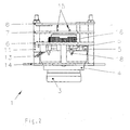
- a securing and monitoring device 1 according to the invention is designed as a flush model in Figure 1 and fits into one (not here illustrated) standard switch box.
- the safety and monitoring device 1 has a structure 2, which is in the installed state located inside a wall.
- the structure 2 may consist of a board. 6 or more boards 7, 8 exist.
- the outer conclusion forms thereby a mounting plate 14.
- This mounting plate 14 is designed so that at the same time for mounting in installation flush-mounted boxes as well Surface-mounted housings is suitable.
- the safety and monitoring device 1 is equipped with a safety button 3 provided.
- the safety button 3 is circular and protrudes above the mounting plate 14. He can be pressed to to enable an emergency operation of a door, a window or the like.
- the safety button 3 is with its electrical connections 15 z. B. on the board 7 ( Figure 2) connected.
- the mechanical attachment takes place either on the same board 7 or as in the embodiment shown by means of a nut 16 on the board 6.
- the safety button 3 an integral part of the structure 2.
- a display 17 which is either the ready Safety button 3 or its operation indicates. As an ad 17, a light source or a mechanical display may be used become.
- the safety button 3 is surrounded by a lighting device 4, which surrounds the safety button 3 ring with game.
- the lighting device 4 consists of a substantially conical plastic ring made of a light-conducting material.
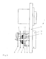
- the plastic ring stands with its smaller one Diameter above the mounting plate 14 before, but not as far as the safety button 3 (see Figures 2 and 3). With its larger diameter is the plastic ring within the structure 2 of light emitting diodes 5, which serve as a light source for the illumination device 4.
- the emitted by the LEDs 5 light enters the rear end face of the plastic ring, is of forwarded to the photoconductive material of the plastic ring and exits the protruding from the mounting plate 14 end of the lighting device 4 off, so that light can be well recognized from the outside. to better light output can be in the lighting device.
- 4 Indentations 18 are in the wholly or partially the light-emitting diodes. 5 plunge.
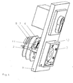
- the structure of the fuse and monitoring device 1 are in the illustrated embodiment three boards 6, 7, 8 housed in parallel planes are arranged to each other and at a distance from each other. It is the Arrangement made so that the middle board 7 with the safety button 3 is connected while the front board 6, the LEDs 5 for the lighting device 4 contacted.
- On the rear board 8 are general utilities such. B. the power supply, Control devices or connections for linking with others Safety and monitoring devices, eg. B. via BUS lines, accommodated.
- the safety and monitoring device When installed, the safety and monitoring device is 1 covered by a frame 9.
- a Flap 10 is arranged, which surrounds the safety button 3.
- the flap 10 In the flap 10 is also a (not shown) mounted glass, the at an actuation of the safety button 3 is moved to the rear and then back to their original position leaves, without the disc is destroyed.
- a sabotage switch 11 is provided, preferably as a microswitch is trained.
- a sabotage switch 11 is provided, preferably as a microswitch is trained.
- the entire Device preferably formed waterproof.
Landscapes
- Business, Economics & Management (AREA)
- Emergency Management (AREA)
- Physics & Mathematics (AREA)
- General Physics & Mathematics (AREA)
- Burglar Alarm Systems (AREA)
- Alarm Systems (AREA)
- Switch Cases, Indication, And Locking (AREA)
- Push-Button Switches (AREA)
Abstract
Description
- Figur 1:
- Eine perspektivische Ansicht der erfindungsgemäßen Sicherungs- und Überwachungsvorrichtung,
- Figur 2:
- eine Seitenansicht der erfindungsgemäßen Sicherungs- und Überwachungsvorrichtung,
- Figur 3:
- einen Querschnitt durch die erfindungsgemäße Sicherungsund Überwachungsvorrichtung,
- Figur 4:
- eine weitere perspektivische Ansicht der erfindungsgemäßen Sicherungs- und Überwachungsvorrichtung und
- Figur 5;
- eine weitere Seitenansicht der erfindungsgemäßen Sicherungs- und Überwachungsvorrichtung.
- 1
- Sicherungs- und Überwachungsvorrichtung
- 2
- Aufbau
- 3
- Sicherheitstaster
- 4
- Beleuchtungseinrichtung
- 5
- Leuchtdiode
- 6
- Platine
- 7
- Platine
- 8
- Platine
- 9
- Rahmen
- 10
- Klappe
- 11
- Sabotageschalter
- 12
- Stift
- 13
- Schaltglied
- 14
- Montageplatte
- 15
- elektrische Anschlüsse
- 16
- Mutter
- 17
- Anzeige
- 18
- Einbuchtungen
Claims (23)
- Sicherungs- und Überwachungsvorrichtung mit einem Aufbau, der die notwendigen Bauteile vorzugsweise auf mindestens einer Platine enthält, einen Sicherheitstaster und einer Beleuchtungseinrichtung sowie einer verschwenkbaren Abdeckung, dadurch gekennzeichnet, dass die Sicherungs- und Überwachungsvorrichtung zur Befestigung eine Montageplatte (14) aufweist, die einerseits von einem Betätigungsknopf des Sicherheitstasters (3) und von einer Beleuchtungseinrichtung (4) durchbrochen wird, dass die Montageplatte (14) von einem Abdeckrahmen überdeckt wird und dass der Sicherheitstaster (3) von der Beleuchtungseinrichtung (4) umschlossen wird.
- Sicherungs- und Überwachungsvorrichtung nach Anspruch 1, dadurch gekennzeichnet, dass der Sicherheitstaster (3) mit mindestens einer der Platinen (6, 7, 8) des Aufbaues (2) elektrisch und/oder mechanisch verbunden ist.
- Sicherungs- und Überwachungsvorrichtung nach einem der vorhergehenden Ansprüche, dadurch gekennzeichnet, dass der Sicherheitstaster (3) eine Anzeige, vorzugsweise eine elektrische Anzeige, enthält.
- Sicherungs- und Überwachungsvorrichtung nach einem der vorhergehenden Ansprüche, dadurch gekennzeichnet, dass eine der Platinen, vorzugsweise die vordere Platine (6), mit der Beleuchtungseinrichtung (4) verbunden ist.
- Sicherungs- und Überwachungsvorrichtung nach Anspruch 1, dadurch gekennzeichnet, dass die Beleuchtungseinrichtung (4) aus einem lichtleitenden Material, insbesondere einem lichtleitenden Kunststoff, besteht.
- Sicherungs- und Überwachungsvorrichtung nach einem der vorhergehenden Ansprüche, dadurch gekennzeichnet, dass der Sicherheitstaster (3) kreisförmig ausgebildet ist und dass die Beleuchtungseinrichtung (4) den Sicherheitstaster (3) ringförmig umgibt.
- Sicherungs- und Überwachungsvorrichtung nach einem der vorhergehenden Ansprüche, dadurch gekennzeichnet, dass zwischen dem Sicherheitstaster (3) und der Beleuchtungseinrichtung (4) ein Spalt gebildet ist.
- Sicherungs- und Überwachungsvorrichtung nach einem der vorhergehenden Ansprüche, dadurch gekennzeichnet, -dass in dem Aufbau (2) mindestens eine Leuchtdiode (5) vorgesehen ist, welche als Lichtquelle für die Beleuchtungseinrichtung (4) dient.
- Sicherungs- und Überwachungsvorrichtung nach einem der vorhergehenden Ansprüche, dadurch gekennzeichnet, dass die andere Stirnseite des ringförmigen Kunststoffteiles innerhalb des Aufbaues (2) angeordnet ist und mit den Leuchtdioden (5) in Verbindung steht, insbesondere an ihnen anliegt bzw. die Leuchtdioden (5) in Einbuchtungen (18) eintauchen.
- Sicherungs- und Überwachungsvorrichtung nach einem der vorhergehenden Ansprüche, dadurch gekennzeichnet, dass der Sicherheitstaster (3) weiter aus der Montageplatte (14) vorsteht als die Beleuchtungseinrichtung (4).
- Sicherungs- und Überwachungsvorrichtung nach einem der vorhergehenden Ansprüche, dadurch gekennzeichnet, dass die Leuchtdioden (5) ein helles oder weißes Licht ausstrahlen.
- Sicherungs- und Überwachungsvorrichtung nach einem der vorhergehenden Ansprüche, dadurch gekennzeichnet, dass die Beleuchtungseinrichtung (4) im Wesentlichen konisch ausgebildet ist und mit ihrem größeren Durchmesser an den Leuchtdioden (5) anliegt.
- Sicherungs- und Überwachungsvorrichtung nach einem der vorhergehenden Ansprüche, dadurch gekennzeichnet, dass die Platinen (6, 7, 8) parallel zueinander und mit Abstand voneinander angeordnet sind.
- Sicherungs- und Überwachungsvorrichtung nach einem der vorhergehenden Ansprüche, dadurch gekennzeichnet, dass eine der Platinen, vorzugsweise die hintere Platine (8), zur Stromversorgung, zur allgemeinen Steuerung und/oder zur Verbindung mehrerer Sicherungs- und Überwachungsvorrichtungen untereinander dient.
- Sicherungs- und Überwachungsvorrichtung'nach einem der vorhergehenden Ansprüche, dadurch gekennzeichnet, dass die Verbindung mehrerer Sicherungs- und Überwachungsvorrichtungen untereinander über eine BUS-Leitung erfolgt.
- Sicherungs- und Überwachungsvorrichtung nach einem der vorhergehenden Ansprüche, dadurch gekennzeichnet, dass in dem Rahmen (9) eine den Sicherheitstaster (3) abdeckende Klappe (10) eingesetzt ist.
- Sicherungs- und Überwachungsvorrichtung nach einem der vorhergehenden Ansprüche, dadurch gekennzeichnet, dass in dem Aufbau (2) ein Sabotageschalter (11) vorgesehen ist, der bei Entfernung des Rahmens (9) und/oder der Klappe (10) schaltet und beispielsweise eine Alarmvorrichtung auslöst.
- Sicherungs- und Überwachungsvorrichtung nach einem der vorhergehenden Ansprüche, dadurch gekennzeichnet, dass der Sabotageschalter (11) als Mikroschalter ausgebildet ist.
- Sicherungs- und Überwachungsvorrichtung nach einem der vorhergehenden Ansprüche, dadurch gekennzeichnet, dass an dem Rahmen (9) und/oder an der Klappe (10) ein Stift (12) gelagert ist, der bei geschlossener Klappe (10) und aufgesetztem Rahmen (9) den Sabotageschalter (11) beaufschlagt.
- Sicherungs- und Überwachungsvorrichtung nach einem der vorhergehenden Ansprüche, dadurch gekennzeichnet, dass in der Klappe (10) eine durchsichtige Scheibe angeordnet ist, die bei einer Betätigung des Sicherheitstasters (3) versetzt wird und sich anschließend zurücksetzen lässt.
- Sicherungs- und Überwachungsvorrichtung nach einem der vorhergehenden Ansprüche, dadurch gekennzeichnet, dass der Aufbau (2) mit allen Platinen (6, 7, 8) in eine Standard-Unterputzdose einsetzbar ist und über die Montageplatte (14) befestigt wird.
- Sicherungs- und Überwachungsvorrichtung nach einem der vorhergehenden Ansprüche, dadurch gekennzeichnet, dass die gesamte Vorrichtung (1) wasserdicht ist.
- Sicherungs- und Überwachungsvorrichtung nach Anspruch 1, dadurch gekennzeichnet, dass der Aufbau (2) der Sicherungs- und Überwachungsvorrichtung (1) in ein Aufputzgehäuse eingebaut wird.
Applications Claiming Priority (2)
| Application Number | Priority Date | Filing Date | Title |
|---|---|---|---|
| DE10234301A DE10234301B3 (de) | 2002-07-26 | 2002-07-26 | Sicherungs- und Überwachungsvorrichtung für Türen, Fenster o. dgl. |
| DE10234301 | 2002-07-26 |
Publications (3)
| Publication Number | Publication Date |
|---|---|
| EP1400936A1 true EP1400936A1 (de) | 2004-03-24 |
| EP1400936B1 EP1400936B1 (de) | 2006-08-30 |
| EP1400936B2 EP1400936B2 (de) | 2012-10-10 |
Family
ID=29723912
Family Applications (1)
| Application Number | Title | Priority Date | Filing Date |
|---|---|---|---|
| EP03014819A Expired - Lifetime EP1400936B2 (de) | 2002-07-26 | 2003-06-30 | Sicherungs- und Überwachungsvorrichtung für Türen, Fenster oder dergleichen |
Country Status (6)
| Country | Link |
|---|---|
| EP (1) | EP1400936B2 (de) |
| AT (1) | ATE338321T1 (de) |
| DE (2) | DE10234301B3 (de) |
| DK (1) | DK1400936T4 (de) |
| ES (1) | ES2271430T5 (de) |
| PT (1) | PT1400936E (de) |
Cited By (6)
| Publication number | Priority date | Publication date | Assignee | Title |
|---|---|---|---|---|
| EP2998488B1 (de) | 2014-09-22 | 2017-12-06 | ASSA ABLOY Sicherheitstechnik GmbH | Fluchtwegsicherungseinrichtung |
| EP3267456A1 (de) * | 2016-07-04 | 2018-01-10 | dormakaba Deutschland GmbH | Auslöseelement |
| CN108054656A (zh) * | 2017-12-08 | 2018-05-18 | 解钟敏 | 一种高压电器用户外安装箱 |
| CN114678785A (zh) * | 2022-05-07 | 2022-06-28 | 鼎圣集团电力工程有限公司 | 一种自动警报的防盗低压开关柜 |
| EP4365922A1 (de) * | 2022-11-07 | 2024-05-08 | dormakaba Deutschland GmbH | Nottaster für eine fluchttürsicherung |
| IT202300017382A1 (it) * | 2023-08-18 | 2025-02-18 | Pizzato Elettrica Srl | Dispositivo per l’arresto di emergenza di una macchina o impianto industriale |
Families Citing this family (4)
| Publication number | Priority date | Publication date | Assignee | Title |
|---|---|---|---|---|
| DE102007005362B3 (de) * | 2006-10-30 | 2008-02-14 | Siemens Ag | Betätigungselement |
| EP2169154A3 (de) | 2008-06-24 | 2013-10-09 | GEZE GmbH | Türzentrale |
| DE102008029698C5 (de) | 2008-06-24 | 2014-12-18 | Geze Gmbh | Türzentrale |
| DE102018204207B4 (de) * | 2018-03-20 | 2025-02-13 | Geze Gmbh | Drahtloskomponente einer Brandschutz-Feststellanlage |
Citations (4)
| Publication number | Priority date | Publication date | Assignee | Title |
|---|---|---|---|---|
| DE19531323A1 (de) * | 1994-10-15 | 1996-04-18 | Geze Gmbh & Co | Ein Diagnose- und/oder Überwachungsverfahren und eine Sicherheitseinrichtung zur Durchführung des Verfahrens für mindestens eine Tür, vorzugsweise in Flucht- und Rettungswegen |
| US6023224A (en) * | 1997-07-29 | 2000-02-08 | The Stanley Works | Door frame with integrated keyless entry system |
| DE19953765A1 (de) * | 1999-11-09 | 2001-05-23 | Geze Gmbh | Sicherungs- und Überwachungsvorrichtung |
| US6420970B1 (en) * | 1998-07-28 | 2002-07-16 | Dorma Gmbh + Co. Kg | Emergency exit door with an emergency door opening system with a control box having an emergency door opening button and display module |
Family Cites Families (8)
| Publication number | Priority date | Publication date | Assignee | Title |
|---|---|---|---|---|
| DE3230412C2 (de) * | 1982-08-16 | 1986-08-28 | Nixdorf Computer Ag, 4790 Paderborn | Vorrichtung für elektrische Geräte zur äußeren Eingabe und/oder Anzeige von Informationen |
| DE3938489C2 (de) * | 1989-11-20 | 2000-06-08 | Dold & Soehne Kg E | In einer Unterputzdose eingebauter Relaisschalter |
| DE19652348C2 (de) * | 1996-12-17 | 1998-12-24 | Dorma Gmbh & Co Kg | Sicherheits-Türterminal mit Sicherheits-NOT-AUF-Taster |
| DE29809106U1 (de) * | 1997-05-23 | 1998-08-27 | Müller, Dirk, 47803 Krefeld | Installationseinrichtung |
| DE19816728A1 (de) * | 1998-04-16 | 1999-10-21 | Abb Patent Gmbh | Elektrisches wassergeschütztes Unterputzinstallationsgerät |
| DE19963022A1 (de) † | 1999-06-27 | 2000-12-28 | Geze Gmbh | Sicherheitsvorrichtung für mindestens eine Tür, vorzugsweise in Flucht- und Rettungswegen |
| DE19934482C5 (de) † | 1999-07-27 | 2013-04-18 | Dorma Gmbh + Co. Kg | Türterminal mit Nottasterabdeckung |
| DE10013352A1 (de) * | 2000-03-17 | 2001-07-12 | Siemens Ag | Slavemodul |
-
2002
- 2002-07-26 DE DE10234301A patent/DE10234301B3/de not_active Revoked
-
2003
- 2003-06-30 DE DE50304831T patent/DE50304831D1/de not_active Expired - Lifetime
- 2003-06-30 DK DK03014819.1T patent/DK1400936T4/da active
- 2003-06-30 ES ES03014819T patent/ES2271430T5/es not_active Expired - Lifetime
- 2003-06-30 PT PT03014819T patent/PT1400936E/pt unknown
- 2003-06-30 EP EP03014819A patent/EP1400936B2/de not_active Expired - Lifetime
- 2003-06-30 AT AT03014819T patent/ATE338321T1/de active
Patent Citations (4)
| Publication number | Priority date | Publication date | Assignee | Title |
|---|---|---|---|---|
| DE19531323A1 (de) * | 1994-10-15 | 1996-04-18 | Geze Gmbh & Co | Ein Diagnose- und/oder Überwachungsverfahren und eine Sicherheitseinrichtung zur Durchführung des Verfahrens für mindestens eine Tür, vorzugsweise in Flucht- und Rettungswegen |
| US6023224A (en) * | 1997-07-29 | 2000-02-08 | The Stanley Works | Door frame with integrated keyless entry system |
| US6420970B1 (en) * | 1998-07-28 | 2002-07-16 | Dorma Gmbh + Co. Kg | Emergency exit door with an emergency door opening system with a control box having an emergency door opening button and display module |
| DE19953765A1 (de) * | 1999-11-09 | 2001-05-23 | Geze Gmbh | Sicherungs- und Überwachungsvorrichtung |
Cited By (10)
| Publication number | Priority date | Publication date | Assignee | Title |
|---|---|---|---|---|
| EP2998488B1 (de) | 2014-09-22 | 2017-12-06 | ASSA ABLOY Sicherheitstechnik GmbH | Fluchtwegsicherungseinrichtung |
| EP3267456A1 (de) * | 2016-07-04 | 2018-01-10 | dormakaba Deutschland GmbH | Auslöseelement |
| EP3267456B1 (de) | 2016-07-04 | 2022-03-23 | dormakaba Deutschland GmbH | Nottaster |
| EP4016572A1 (de) * | 2016-07-04 | 2022-06-22 | dormakaba Deutschland GmbH | Auslöseelement |
| EP4016572B1 (de) | 2016-07-04 | 2024-04-17 | dormakaba Deutschland GmbH | Auslöseelement |
| CN108054656A (zh) * | 2017-12-08 | 2018-05-18 | 解钟敏 | 一种高压电器用户外安装箱 |
| CN114678785A (zh) * | 2022-05-07 | 2022-06-28 | 鼎圣集团电力工程有限公司 | 一种自动警报的防盗低压开关柜 |
| EP4365922A1 (de) * | 2022-11-07 | 2024-05-08 | dormakaba Deutschland GmbH | Nottaster für eine fluchttürsicherung |
| IT202300017382A1 (it) * | 2023-08-18 | 2025-02-18 | Pizzato Elettrica Srl | Dispositivo per l’arresto di emergenza di una macchina o impianto industriale |
| EP4510158A1 (de) * | 2023-08-18 | 2025-02-19 | Pizzato Elettrica S.r.l. | Vorrichtung zum notstoppen einer industriellen maschine oder anlage |
Also Published As
| Publication number | Publication date |
|---|---|
| EP1400936B2 (de) | 2012-10-10 |
| PT1400936E (pt) | 2007-01-31 |
| DE50304831D1 (de) | 2006-10-12 |
| DK1400936T4 (da) | 2013-01-28 |
| ES2271430T3 (es) | 2007-04-16 |
| ES2271430T5 (es) | 2013-03-06 |
| DE10234301B3 (de) | 2004-01-15 |
| EP1400936B1 (de) | 2006-08-30 |
| ATE338321T1 (de) | 2006-09-15 |
| DK1400936T3 (da) | 2007-01-08 |
Similar Documents
| Publication | Publication Date | Title |
|---|---|---|
| DE112017002169B4 (de) | Stromversorgungseinheit | |
| DE102019204304A1 (de) | Sicherheitsschalter | |
| DE19722922A1 (de) | Spannungsversorgungsvorrichtung | |
| EP1544955A2 (de) | Steckdose für elektrische Steckverbindungen | |
| EP1400936B2 (de) | Sicherungs- und Überwachungsvorrichtung für Türen, Fenster oder dergleichen | |
| EP3267451B1 (de) | Sicherheitssystem | |
| DE60030864T2 (de) | Notrufschalter oder zerbrechbare glaseinheiten | |
| DE102012106923A1 (de) | Schaltvorrichtung mit Funkmodul und Deaktivierungsfunktion | |
| DE4331665A1 (de) | Türbeschlag mit Alarmanlage | |
| EP1065577B1 (de) | Sicherheitsvorrichtung für mindestens eine Tür, vorzugsweise in Flucht-und Rettungswegen | |
| EP1391904B2 (de) | Sicherungs-und Überwachungsvorrichtung für Türen, Fenster oder dergleichen | |
| EP2194223B1 (de) | Sicherheitsvorrichtung | |
| DE4411290A1 (de) | Sensor | |
| DE10118120C1 (de) | Beleuchtungssystem für Handhaben | |
| EP1389810B1 (de) | Gerät eines elektronischen Überwachungssystems, insbesondere eines Videoüberwachungssystems | |
| EP2375520A1 (de) | Montageanordnung, insbesondere für die Hauskommunikation | |
| DE9301267U1 (de) | Türbeschlag mit Alarmanlage | |
| DE19503732C2 (de) | Diebstahlsicherungsvorrichtung für elektrische Geräte und Maschinen | |
| DE102018204207B4 (de) | Drahtloskomponente einer Brandschutz-Feststellanlage | |
| DE9102114U1 (de) | Anordnung zur Alarmauslösung bei Einbruchsversuchen | |
| DE102010037880A1 (de) | Rahmenprofileinsatz, damit ausgestattete Flügelanlage und Montageverfahren dafür | |
| DE3735331C2 (de) | ||
| EP2221786B1 (de) | Gehäuseerweiterungsvorrichtung mit einem mechanischen Betätigungselement | |
| DE202006006662U1 (de) | Steckdose mit Leuchtkranz | |
| EP0385049B1 (de) | Türwächter |
Legal Events
| Date | Code | Title | Description |
|---|---|---|---|
| PUAI | Public reference made under article 153(3) epc to a published international application that has entered the european phase |
Free format text: ORIGINAL CODE: 0009012 |
|
| AK | Designated contracting states |
Kind code of ref document: A1 Designated state(s): AT BE BG CH CY CZ DE DK EE ES FI FR GB GR HU IE IT LI LU MC NL PT RO SE SI SK TR |
|
| AX | Request for extension of the european patent |
Extension state: AL LT LV MK |
|
| 17P | Request for examination filed |
Effective date: 20040924 |
|
| AKX | Designation fees paid |
Designated state(s): AT BE BG CH CY CZ DE DK EE ES FI FR GB GR HU IE IT LI LU MC NL PT RO SE SI SK TR |
|
| 17Q | First examination report despatched |
Effective date: 20041206 |
|
| GRAP | Despatch of communication of intention to grant a patent |
Free format text: ORIGINAL CODE: EPIDOSNIGR1 |
|
| GRAS | Grant fee paid |
Free format text: ORIGINAL CODE: EPIDOSNIGR3 |
|
| GRAA | (expected) grant |
Free format text: ORIGINAL CODE: 0009210 |
|
| AK | Designated contracting states |
Kind code of ref document: B1 Designated state(s): AT BE BG CH CY CZ DE DK EE ES FI FR GB GR HU IE IT LI LU MC NL PT RO SE SI SK TR |
|
| PG25 | Lapsed in a contracting state [announced via postgrant information from national office to epo] |
Ref country code: CZ Free format text: LAPSE BECAUSE OF FAILURE TO SUBMIT A TRANSLATION OF THE DESCRIPTION OR TO PAY THE FEE WITHIN THE PRESCRIBED TIME-LIMIT Effective date: 20060830 Ref country code: IT Free format text: LAPSE BECAUSE OF FAILURE TO SUBMIT A TRANSLATION OF THE DESCRIPTION OR TO PAY THE FEE WITHIN THE PRESCRIBED TIME-LIMIT;WARNING: LAPSES OF ITALIAN PATENTS WITH EFFECTIVE DATE BEFORE 2007 MAY HAVE OCCURRED AT ANY TIME BEFORE 2007. THE CORRECT EFFECTIVE DATE MAY BE DIFFERENT FROM THE ONE RECORDED. Effective date: 20060830 Ref country code: SI Free format text: LAPSE BECAUSE OF FAILURE TO SUBMIT A TRANSLATION OF THE DESCRIPTION OR TO PAY THE FEE WITHIN THE PRESCRIBED TIME-LIMIT Effective date: 20060830 Ref country code: RO Free format text: LAPSE BECAUSE OF FAILURE TO SUBMIT A TRANSLATION OF THE DESCRIPTION OR TO PAY THE FEE WITHIN THE PRESCRIBED TIME-LIMIT Effective date: 20060830 Ref country code: IE Free format text: LAPSE BECAUSE OF FAILURE TO SUBMIT A TRANSLATION OF THE DESCRIPTION OR TO PAY THE FEE WITHIN THE PRESCRIBED TIME-LIMIT Effective date: 20060830 Ref country code: SK Free format text: LAPSE BECAUSE OF FAILURE TO SUBMIT A TRANSLATION OF THE DESCRIPTION OR TO PAY THE FEE WITHIN THE PRESCRIBED TIME-LIMIT Effective date: 20060830 |
|
| REG | Reference to a national code |
Ref country code: GB Ref legal event code: FG4D Free format text: NOT ENGLISH |
|
| REG | Reference to a national code |
Ref country code: CH Ref legal event code: EP |
|
| REG | Reference to a national code |
Ref country code: IE Ref legal event code: FG4D Free format text: LANGUAGE OF EP DOCUMENT: GERMAN |
|
| REF | Corresponds to: |
Ref document number: 50304831 Country of ref document: DE Date of ref document: 20061012 Kind code of ref document: P |
|
| REG | Reference to a national code |
Ref country code: SE Ref legal event code: TRGR |
|
| PG25 | Lapsed in a contracting state [announced via postgrant information from national office to epo] |
Ref country code: BG Free format text: LAPSE BECAUSE OF FAILURE TO SUBMIT A TRANSLATION OF THE DESCRIPTION OR TO PAY THE FEE WITHIN THE PRESCRIBED TIME-LIMIT Effective date: 20061130 |
|
| GBT | Gb: translation of ep patent filed (gb section 77(6)(a)/1977) |
Effective date: 20061127 |
|
| REG | Reference to a national code |
Ref country code: CH Ref legal event code: NV Representative=s name: BOVARD AG PATENTANWAELTE |
|
| REG | Reference to a national code |
Ref country code: DK Ref legal event code: T3 |
|
| REG | Reference to a national code |
Ref country code: PT Ref legal event code: SC4A Free format text: AVAILABILITY OF NATIONAL TRANSLATION Effective date: 20061128 |
|
| ET | Fr: translation filed | ||
| REG | Reference to a national code |
Ref country code: ES Ref legal event code: FG2A Ref document number: 2271430 Country of ref document: ES Kind code of ref document: T3 |
|
| REG | Reference to a national code |
Ref country code: IE Ref legal event code: FD4D |
|
| PLBI | Opposition filed |
Free format text: ORIGINAL CODE: 0009260 |
|
| 26 | Opposition filed |
Opponent name: GEZE GMBH Effective date: 20070523 |
|
| PLAX | Notice of opposition and request to file observation + time limit sent |
Free format text: ORIGINAL CODE: EPIDOSNOBS2 |
|
| PLBB | Reply of patent proprietor to notice(s) of opposition received |
Free format text: ORIGINAL CODE: EPIDOSNOBS3 |
|
| NLR1 | Nl: opposition has been filed with the epo |
Opponent name: GEZE GMBH |
|
| PG25 | Lapsed in a contracting state [announced via postgrant information from national office to epo] |
Ref country code: MC Free format text: LAPSE BECAUSE OF NON-PAYMENT OF DUE FEES Effective date: 20070630 |
|
| PG25 | Lapsed in a contracting state [announced via postgrant information from national office to epo] |
Ref country code: GR Free format text: LAPSE BECAUSE OF FAILURE TO SUBMIT A TRANSLATION OF THE DESCRIPTION OR TO PAY THE FEE WITHIN THE PRESCRIBED TIME-LIMIT Effective date: 20061201 |
|
| PLAB | Opposition data, opponent's data or that of the opponent's representative modified |
Free format text: ORIGINAL CODE: 0009299OPPO |
|
| R26 | Opposition filed (corrected) |
Opponent name: GEZE GMBH Effective date: 20070523 |
|
| PG25 | Lapsed in a contracting state [announced via postgrant information from national office to epo] |
Ref country code: EE Free format text: LAPSE BECAUSE OF FAILURE TO SUBMIT A TRANSLATION OF THE DESCRIPTION OR TO PAY THE FEE WITHIN THE PRESCRIBED TIME-LIMIT Effective date: 20060830 |
|
| NLR1 | Nl: opposition has been filed with the epo |
Opponent name: GEZE GMBH |
|
| APBM | Appeal reference recorded |
Free format text: ORIGINAL CODE: EPIDOSNREFNO |
|
| APBP | Date of receipt of notice of appeal recorded |
Free format text: ORIGINAL CODE: EPIDOSNNOA2O |
|
| APAH | Appeal reference modified |
Free format text: ORIGINAL CODE: EPIDOSCREFNO |
|
| APBQ | Date of receipt of statement of grounds of appeal recorded |
Free format text: ORIGINAL CODE: EPIDOSNNOA3O |
|
| PG25 | Lapsed in a contracting state [announced via postgrant information from national office to epo] |
Ref country code: CY Free format text: LAPSE BECAUSE OF FAILURE TO SUBMIT A TRANSLATION OF THE DESCRIPTION OR TO PAY THE FEE WITHIN THE PRESCRIBED TIME-LIMIT Effective date: 20060830 |
|
| PG25 | Lapsed in a contracting state [announced via postgrant information from national office to epo] |
Ref country code: TR Free format text: LAPSE BECAUSE OF FAILURE TO SUBMIT A TRANSLATION OF THE DESCRIPTION OR TO PAY THE FEE WITHIN THE PRESCRIBED TIME-LIMIT Effective date: 20060830 Ref country code: HU Free format text: LAPSE BECAUSE OF FAILURE TO SUBMIT A TRANSLATION OF THE DESCRIPTION OR TO PAY THE FEE WITHIN THE PRESCRIBED TIME-LIMIT Effective date: 20070301 |
|
| REG | Reference to a national code |
Ref country code: CH Ref legal event code: PCOW Free format text: DORMA GMBH + CO. KG;DORMA PLATZ 1;58256 ENNEPETAL (DE) |
|
| REG | Reference to a national code |
Ref country code: CH Ref legal event code: PFA Owner name: DORMA GMBH + CO. KG Free format text: DORMA GMBH + CO. KG#DORMA PLATZ 1#58256 ENNEPETAL (DE) -TRANSFER TO- DORMA GMBH + CO. KG#DORMA PLATZ 1#58256 ENNEPETAL (DE) |
|
| APBU | Appeal procedure closed |
Free format text: ORIGINAL CODE: EPIDOSNNOA9O |
|
| PUAH | Patent maintained in amended form |
Free format text: ORIGINAL CODE: 0009272 |
|
| STAA | Information on the status of an ep patent application or granted ep patent |
Free format text: STATUS: PATENT MAINTAINED AS AMENDED |
|
| 27A | Patent maintained in amended form |
Effective date: 20121010 |
|
| AK | Designated contracting states |
Kind code of ref document: B2 Designated state(s): AT BE BG CH CY CZ DE DK EE ES FI FR GB GR HU IE IT LI LU MC NL PT RO SE SI SK TR |
|
| REG | Reference to a national code |
Ref country code: CH Ref legal event code: AEN Free format text: AUFRECHTERHALTUNG DES PATENTES IN GEAENDERTER FORM |
|
| REG | Reference to a national code |
Ref country code: DE Ref legal event code: R102 Ref document number: 50304831 Country of ref document: DE Effective date: 20121010 |
|
| REG | Reference to a national code |
Ref country code: SE Ref legal event code: RPEO |
|
| REG | Reference to a national code |
Ref country code: DK Ref legal event code: T4 |
|
| REG | Reference to a national code |
Ref country code: NL Ref legal event code: T3 |
|
| REG | Reference to a national code |
Ref country code: ES Ref legal event code: DC2A Ref document number: 2271430 Country of ref document: ES Kind code of ref document: T5 Effective date: 20130306 |
|
| PGFP | Annual fee paid to national office [announced via postgrant information from national office to epo] |
Ref country code: AT Payment date: 20120613 Year of fee payment: 10 |
|
| PGFP | Annual fee paid to national office [announced via postgrant information from national office to epo] |
Ref country code: SE Payment date: 20130619 Year of fee payment: 11 Ref country code: CH Payment date: 20130621 Year of fee payment: 11 Ref country code: DK Payment date: 20130619 Year of fee payment: 11 Ref country code: LU Payment date: 20130621 Year of fee payment: 11 |
|
| PGFP | Annual fee paid to national office [announced via postgrant information from national office to epo] |
Ref country code: NL Payment date: 20130619 Year of fee payment: 11 Ref country code: FI Payment date: 20130613 Year of fee payment: 11 |
|
| PGFP | Annual fee paid to national office [announced via postgrant information from national office to epo] |
Ref country code: BE Payment date: 20130619 Year of fee payment: 11 |
|
| PGFP | Annual fee paid to national office [announced via postgrant information from national office to epo] |
Ref country code: PT Payment date: 20130102 Year of fee payment: 11 |
|
| REG | Reference to a national code |
Ref country code: PT Ref legal event code: MM4A Free format text: LAPSE DUE TO NON-PAYMENT OF FEES Effective date: 20141231 |
|
| REG | Reference to a national code |
Ref country code: DK Ref legal event code: EBP Effective date: 20140630 |
|
| REG | Reference to a national code |
Ref country code: NL Ref legal event code: V1 Effective date: 20150101 |
|
| REG | Reference to a national code |
Ref country code: DE Ref legal event code: R081 Ref document number: 50304831 Country of ref document: DE Owner name: DORMAKABA DEUTSCHLAND GMBH, DE Free format text: FORMER OWNER: DORMA GMBH + CO. KG, 58256 ENNEPETAL, DE Effective date: 20141211 Ref country code: DE Ref legal event code: R081 Ref document number: 50304831 Country of ref document: DE Owner name: DORMA DEUTSCHLAND GMBH, DE Free format text: FORMER OWNER: DORMA GMBH + CO. KG, 58256 ENNEPETAL, DE Effective date: 20141211 |
|
| PG25 | Lapsed in a contracting state [announced via postgrant information from national office to epo] |
Ref country code: PT Free format text: LAPSE BECAUSE OF NON-PAYMENT OF DUE FEES Effective date: 20141231 Ref country code: LU Free format text: LAPSE BECAUSE OF NON-PAYMENT OF DUE FEES Effective date: 20140630 Ref country code: FI Free format text: LAPSE BECAUSE OF NON-PAYMENT OF DUE FEES Effective date: 20140630 |
|
| REG | Reference to a national code |
Ref country code: CH Ref legal event code: PL |
|
| REG | Reference to a national code |
Ref country code: AT Ref legal event code: MM01 Ref document number: 338321 Country of ref document: AT Kind code of ref document: T Effective date: 20140630 |
|
| REG | Reference to a national code |
Ref country code: SE Ref legal event code: EUG |
|
| REG | Reference to a national code |
Ref country code: FR Ref legal event code: CJ Effective date: 20150206 Ref country code: FR Ref legal event code: CA Effective date: 20150206 |
|
| PG25 | Lapsed in a contracting state [announced via postgrant information from national office to epo] |
Ref country code: NL Free format text: LAPSE BECAUSE OF NON-PAYMENT OF DUE FEES Effective date: 20150101 |
|
| REG | Reference to a national code |
Ref country code: ES Ref legal event code: PC2A Owner name: DORMA DEUTSCHLAND GMBH Effective date: 20150415 |
|
| PG25 | Lapsed in a contracting state [announced via postgrant information from national office to epo] |
Ref country code: CH Free format text: LAPSE BECAUSE OF NON-PAYMENT OF DUE FEES Effective date: 20140630 Ref country code: LI Free format text: LAPSE BECAUSE OF NON-PAYMENT OF DUE FEES Effective date: 20140630 |
|
| REG | Reference to a national code |
Ref country code: DE Ref legal event code: R082 Ref document number: 50304831 Country of ref document: DE Representative=s name: BALDER IP LAW, S.L., ES |
|
| PG25 | Lapsed in a contracting state [announced via postgrant information from national office to epo] |
Ref country code: AT Free format text: LAPSE BECAUSE OF NON-PAYMENT OF DUE FEES Effective date: 20140630 Ref country code: SE Free format text: LAPSE BECAUSE OF NON-PAYMENT OF DUE FEES Effective date: 20140701 |
|
| PG25 | Lapsed in a contracting state [announced via postgrant information from national office to epo] |
Ref country code: DK Free format text: LAPSE BECAUSE OF NON-PAYMENT OF DUE FEES Effective date: 20140630 |
|
| REG | Reference to a national code |
Ref country code: FR Ref legal event code: PLFP Year of fee payment: 14 |
|
| REG | Reference to a national code |
Ref country code: DE Ref legal event code: R082 Ref document number: 50304831 Country of ref document: DE Representative=s name: BALDER IP LAW, S.L., ES Ref country code: DE Ref legal event code: R081 Ref document number: 50304831 Country of ref document: DE Owner name: DORMAKABA DEUTSCHLAND GMBH, DE Free format text: FORMER OWNER: DORMA DEUTSCHLAND GMBH, 58256 ENNEPETAL, DE |
|
| REG | Reference to a national code |
Ref country code: FR Ref legal event code: PLFP Year of fee payment: 15 |
|
| PG25 | Lapsed in a contracting state [announced via postgrant information from national office to epo] |
Ref country code: BE Free format text: LAPSE BECAUSE OF NON-PAYMENT OF DUE FEES Effective date: 20140630 |
|
| REG | Reference to a national code |
Ref country code: ES Ref legal event code: PC2A Owner name: DORMAKABA DEUTSCHLAND GMBH Effective date: 20171004 |
|
| REG | Reference to a national code |
Ref country code: FR Ref legal event code: CD Owner name: DORMA GMBH + CO. KG, DE Effective date: 20171003 |
|
| REG | Reference to a national code |
Ref country code: FR Ref legal event code: PLFP Year of fee payment: 16 |
|
| PGFP | Annual fee paid to national office [announced via postgrant information from national office to epo] |
Ref country code: IT Payment date: 20220627 Year of fee payment: 20 Ref country code: GB Payment date: 20220621 Year of fee payment: 20 |
|
| PGFP | Annual fee paid to national office [announced via postgrant information from national office to epo] |
Ref country code: FR Payment date: 20220628 Year of fee payment: 20 |
|
| PGFP | Annual fee paid to national office [announced via postgrant information from national office to epo] |
Ref country code: ES Payment date: 20220829 Year of fee payment: 20 Ref country code: DE Payment date: 20220620 Year of fee payment: 20 |
|
| REG | Reference to a national code |
Ref country code: DE Ref legal event code: R071 Ref document number: 50304831 Country of ref document: DE |
|
| REG | Reference to a national code |
Ref country code: GB Ref legal event code: PE20 Expiry date: 20230629 |
|
| REG | Reference to a national code |
Ref country code: ES Ref legal event code: FD2A Effective date: 20230726 |
|
| PG25 | Lapsed in a contracting state [announced via postgrant information from national office to epo] |
Ref country code: GB Free format text: LAPSE BECAUSE OF EXPIRATION OF PROTECTION Effective date: 20230629 Ref country code: ES Free format text: LAPSE BECAUSE OF EXPIRATION OF PROTECTION Effective date: 20230701 |