EP1401002A2 - Interrupteur électrique avec indicateur d'état - Google Patents
Interrupteur électrique avec indicateur d'état Download PDFInfo
- Publication number
- EP1401002A2 EP1401002A2 EP03020703A EP03020703A EP1401002A2 EP 1401002 A2 EP1401002 A2 EP 1401002A2 EP 03020703 A EP03020703 A EP 03020703A EP 03020703 A EP03020703 A EP 03020703A EP 1401002 A2 EP1401002 A2 EP 1401002A2
- Authority
- EP
- European Patent Office
- Prior art keywords
- switching device
- display
- wheel
- drive
- indicator wheel
- Prior art date
- Legal status (The legal status is an assumption and is not a legal conclusion. Google has not performed a legal analysis and makes no representation as to the accuracy of the status listed.)
- Withdrawn
Links
Images


Classifications
-
- H—ELECTRICITY
- H01—ELECTRIC ELEMENTS
- H01H—ELECTRIC SWITCHES; RELAYS; SELECTORS; EMERGENCY PROTECTIVE DEVICES
- H01H50/00—Details of electromagnetic relays
- H01H50/08—Indicators; Distinguishing marks
-
- H—ELECTRICITY
- H01—ELECTRIC ELEMENTS
- H01H—ELECTRIC SWITCHES; RELAYS; SELECTORS; EMERGENCY PROTECTIVE DEVICES
- H01H51/00—Electromagnetic relays
- H01H51/02—Non-polarised relays
- H01H51/04—Non-polarised relays with single armature; with single set of ganged armatures
- H01H51/06—Armature is movable between two limit positions of rest and is moved in one direction due to energisation of an electromagnet and after the electromagnet is de-energised is returned by energy stored during the movement in the first direction, e.g. by using a spring, by using a permanent magnet, by gravity
- H01H51/08—Contacts alternately opened and closed by successive cycles of energisation and de-energisation of the electromagnet, e.g. by use of a ratchet
- H01H51/082—Contacts alternately opened and closed by successive cycles of energisation and de-energisation of the electromagnet, e.g. by use of a ratchet using rotating ratchet mechanism
-
- H—ELECTRICITY
- H01—ELECTRIC ELEMENTS
- H01H—ELECTRIC SWITCHES; RELAYS; SELECTORS; EMERGENCY PROTECTIVE DEVICES
- H01H50/00—Details of electromagnetic relays
- H01H50/16—Magnetic circuit arrangements
- H01H50/18—Movable parts of magnetic circuits, e.g. armature
- H01H50/32—Latching movable parts mechanically
- H01H50/326—Latching movable parts mechanically with manual intervention, e.g. for testing, resetting or mode selection
-
- H—ELECTRICITY
- H01—ELECTRIC ELEMENTS
- H01H—ELECTRIC SWITCHES; RELAYS; SELECTORS; EMERGENCY PROTECTIVE DEVICES
- H01H9/00—Details of switching devices, not covered by groups H01H1/00 - H01H7/00
- H01H9/16—Indicators for switching condition, e.g. "on" or "off"
Definitions
- the invention relates to an electrical switching device, in particular modular installation device with a switch position indicator, by which the operating state of the switching device after is visible on the outside.
- a switch position indicator is special required for a remote-controlled switching device, in which either no manual operation is provided, or where the operating status of the device is not clearly on the Position of the manual control element can be read.
- a switch position indicator at least one color-coded and / or with a word message provided display field, which if there is an associated Operating status through a housing window from the outside is visible.
- Switch position indicators are that they indicate the operating status of the device should show clearly. Furthermore should the mechanics required for the switch position indicator Do not impair device function. For economic The switch position indicator should also be considered be as simple as possible to the material costs and to keep the assembly effort low.
- the invention has for its object an electrical Switchgear with one with regard to the above requirements to indicate the upgraded switch position indicator.
- the switch position indicator a rotating display wheel with several over whose scope evenly distributed display fields, where a number of corresponding to the number of display fields Indicator positions of the indicator wheel exist, in each of which always a display field through a housing window from the outside is visible. This continues to drive the indicator wheel connected to the switching drive of the switching device in such a way that the indicator wheel in one direction of rotation during a switching operation from the display position before the switching process in the next following according to the direction of rotation Display position is rotated.
- the indicator wheel is provided with locking means provided with a corresponding housing-fixed Interact with counter bearings to form a backstop.
- a backstop prevents undesired backward rotation of the indicator wheel against the direction of rotation, e.g. as a result a shock to the switching device or when jumping back of the switch drive in the rest position, and thus increases the operational safety of the switch position indicator.
- the backstop expediently has orientation the display wheel has several discrete locking points.
- Such a discrete backstop is e.g. from a ratchet known from here.
- the backstop is a limited reverse rotation tolerated.
- the blocking effect occurs only when the orientation of the indicator wheel a blocking point has been reached. This is especially then an advantage if every display position with a blocking point matches, since such a return of the indicator wheel then always is stopped when the display position is reached exactly.
- a particularly advantageous implementation of such a backstop is by a in the circumferential direction of the indicator wheel sawtooth-shaped relief on the front of the indicator wheel formed with at least one acting as a counter bearing and radially oriented with respect to the axis of the indicator wheel Counterpart of the housing cooperates.
- each counter web is designed like a ramp, so it assigns one a sawtooth essentially complementary shape. This The shape favors a low-friction sliding of the locking means over the or each counter bearing.
- the axial mobility required for this sliding the locking bars with respect to the or each counter bearing is on enables in a particularly simple manner that the display wheel is slidably mounted in the axial direction.
- a spring element is also provided, the the indicator wheel, and thus the locking bars, in the axial direction pushes against the or each counterpart.
- the spring element is preferably in one piece with connected to the display wheel.
- a preferred embodiment is for rotating the indicator wheel an impeller or gear connected in a rotationally fixed manner provided which with the switching drive of the switching device interacts.
- Such an impeller can be used a substantially linear movement of the switching drive in in a particularly simple manner in the rotary movement of the indicator wheel implement.
- these are preferably elastically bendable.
- the impeller is preferably in one piece molded onto the display wheel.
- the drive wings are radial aligned.
- the drive blades are spiral-like against the direction of rotation bent.
- One embodiment is particularly advantageous, in which the drive wing simultaneously as part of the backstop are used in the manner of pawls cooperate with the counter bearing.
- One solenoid and one tangential to the indicator wheel moving yoke plate comprehensive switching drive also easily used to drive the indicator wheel, by a free end designed as a slide Yoke plate in engagement with the drive blades of the impeller stands.
- plastic in particular Polyoxymethylene (POM), especially as material for the display wheel suitable.
- POM Polyoxymethylene
- Plastic is particularly the manufacture of the indicator wheel enabled as an inexpensive molded part.
- the electrical shown in FIG 1 with the housing 1 open Switchgear 2 has two input terminals 3a, 3b and two output terminals 4a, 4b and a magnetic switching drive 5 for remote-controlled triggering of a switching process Mistake.
- the input terminal 3b and the output terminal 4b are behind the input terminal with regard to the drawing level 3a or the output terminal 4a arranged and only hinted visible.
- the switching drive 5 comprises a magnetic coil 6 and one arranged at a head end 7 of the magnetic coil 6 Yoke plate 8.
- the yoke plate 8 is shown in FIG Rest position with a small distance to the head end 7 such hung up in a projection along the coil, axis 9 covers the cross section of the magnet coil 6 approximately.
- the Yoke plate 8 is pivotally mounted on a side edge 10, so that they face towards or away from the headboard 7 is pivotable.
- the free end opposite the side edge 10 11 is formed into a slide-like projection, the one with an approximately parallel to the coil axis 9 Switch slide 12 with respect to a direction of force along the Coil axis 9 is in a positive connection.
- One on Switch slide 12 mounted coil spring 13 holds the Switch slide 12 and the yoke plate 8 connected to it under tension in the rest position shown.
- the slide switch 12 projects with a button end 14 for manual Actuation of the switching device 2 out of the housing 1.
- the opposite end 15 lies approximately on the circumference of a - Put simply, square ratchet wheels 16.
- switching device 2 When switching device 2 is operated, be it by manual Pushing the button end 14 or by applying an electrical
- the yoke plate 8 becomes voltage to the magnetic coil 6 attracted to the head end 7 by magnetic force and the slide switch 12 parallel to the coil axis 9 in the direction of the switching wheel 16 moves.
- the end 15 of the Switch slide 12 a torque on the switching wheel 16 and turns it one-eighth of a turn with each shift in a predetermined direction of rotation 17 (in the illustrated Example clockwise).
- the switching wheel 16 is not on with a switch contact 18 in a mechanical manner Connection so that when the ratchet wheel 16 the switch contact 18 back and forth between two switch positions is switched.
- the switching device 2 has a switch position indicator 19 provided, the main component of which is shown in more detail in FIG Display wheel is 20.
- the indicator wheel 20 is eight contiguous and even over its circumference distributed display fields 21, each one Wear the corresponding marking for the switching status.
- the fields 21 are alternately colored green and red.
- On one end 22 of the indicator wheel 20 are eight in the direction the axis 23 of the indicator wheel 20 protruding, each in Essentially sawtooth-shaped locking webs 24 are formed.
- the Locking webs 24 together form a circumferential around the axis 23 Wreath, the front of which is like a saw blade has asymmetrically jagged relief.
- the locking bars 24, that act as part of a backstop define one fixed predetermined direction of rotation 25 of the indicator wheel 20 by the oblique flank 26 of each locking web 24 in the circumferential direction 25 is aligned, while the steep flank 27 each in the direction opposite to the direction of rotation 25 stands.
- the impeller 29 On the end face 28 of the display wheel facing away from the locking webs 24 20 closes an impeller 29 uniaxially with respect to the Axis 23 on the display wheel 20.
- the impeller 29 is included arranged at a small axial distance from the display wheel 20 and connected in one piece by a shaft 30.
- the impeller 29 has eight drive vanes 31, which are uniform over the The circumference of the shaft 30 is formed integrally and radially protrude outwards.
- the struts 33 are mirror images of one another with respect to axis 23 trained and together form about a U-shape, which too the side of each strut 33 facing away from the impeller 29 is open and its plane is parallel to axis 23.
- Each strut 33 is based on that of the impeller 29 adjacent end initially approximately diagonally from the axis 23 led away and has a curved knee area 34, over which the free end 35 of each strut 33 in turn is bent diagonally to the axis 23.
- Shapes are the struts 33 in particular in the direction the axis 23 elastically bendable and set one Bending a restoring force.
- the display wheel 20, the locking webs 24, the impeller 29, the shaft 30 and the struts 33 form in the embodiment shown in FIG an integrally connected unit, which as Setting roller 36 is called.
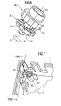
- FIG 3 shows a variant of the adjusting roller 36.
- the shaft in this embodiment 30 beyond the end face 32 of the impeller to a shaft extension 37 trained.
- Coil spring 38 which can be placed on the shaft extension 37 and which winds around the shaft extension 37 in the assembled state.
- the operation of the adjusting roller 36 as a switch position indicator 19 is clear from an overview of FIGS. 1 to 5.
- the adjusting roller 36 is in such an assembled state one adjacent to a housing front 39 within the Housing 1 arranged housing guide 40 used that on the one hand, a partial area of the circumference of the display wheel 20 through a housing window introduced into the housing front side 39 41 is visible from the outside.
- the housing guide On the other hand, 40 is attached such that when the Adjusting roller 36 the slide-like free end 11 the yoke plate 8 in the between two adjacent drive wings 31 intervening formed.
- the yoke plate 8 As long as the yoke plate 8 is shown in FIG Rest position is the adjusting roller 36 through the teeth the free end 11 with the impeller 29 orientation or fixed in rotation in a display position.
- the display fields 21 are such over the circumference of the indicator wheel 20 distributed that in each display position only one display field 21 is visible through the housing window 41. On this is the current switching state of the switching device 2 clearly displayed to the outside world.
- the locking webs 24 of the adjusting roller 36 contribute to education a backstop with one of two counter webs 42 formed counter bearing together.
- the counter webs 42 are like 4 and 5 it becomes clear within the housing guide 40 arranged and radially aligned with respect to the axis 23.
- Each counter web 42 is constructed in a ramp-like manner has an inclined sliding surface 43 which in the direction of rotation 25 of the adjusting roller 36 opposite direction looks.
- a locking surface pointing in the direction of rotation 25 44 of each counter web 42 is aligned approximately parallel to the axis 23.
- the eight display positions are at the same time blocking points by the locking bars 24 and the counter webs 42 formed backstop, i.e. Orientations of the adjusting roller 36, in which its backward rotation counter to the direction of rotation 25 by by stop the flank 27 on the locking surface 44 is prevented.
- each drive wing 31 has an approximately semicircular shape Has cross-section.
- the drive wings spring 31 in particular in the radial direction the axis 23.
- the drive wing 31 simultaneously form locking means to make a backstop by turning it with two counter webs 42 of the housing shown in FIG 1 interact.
- the counter webs 42 are in this Execution of the housing 1 on a housing guide 40 for the Shaft 30 molded on the outside and are with respect to the axis 23 in turn aligned approximately radially.
- FIG. 8 The interaction between the drive wings 31 and Counter web 42 for forming a backstop is shown in FIG. 8 shown.
- Each drive wing 31 acts like a pawl, i.e. that the drive wing 31 the resistance exerted by the counter web 42 essentially evades radially inwards and after passing through the opposite web 42 by snapping back into the starting position in the circumferential direction 25 seen locked behind the counter web 42.
- An axial, spring-loaded mounting of the adjusting roller 36, as in the exemplary embodiments according to FIG. 2 and FIG. 3 was provided here by the pawl-like design the drive wing 31 is not required.
Landscapes
- Physics & Mathematics (AREA)
- Electromagnetism (AREA)
- Displays For Variable Information Using Movable Means (AREA)
- Rotary Switch, Piano Key Switch, And Lever Switch (AREA)
Applications Claiming Priority (2)
| Application Number | Priority Date | Filing Date | Title |
|---|---|---|---|
| DE10244182 | 2002-09-23 | ||
| DE2002144182 DE10244182B3 (de) | 2002-09-23 | 2002-09-23 | Elektrisches Schaltgerät mit Schaltstellungsanzeige |
Publications (2)
| Publication Number | Publication Date |
|---|---|
| EP1401002A2 true EP1401002A2 (fr) | 2004-03-24 |
| EP1401002A3 EP1401002A3 (fr) | 2005-10-05 |
Family
ID=30775594
Family Applications (1)
| Application Number | Title | Priority Date | Filing Date |
|---|---|---|---|
| EP03020703A Withdrawn EP1401002A3 (fr) | 2002-09-23 | 2003-09-11 | Interrupteur électrique avec indicateur d'état |
Country Status (2)
| Country | Link |
|---|---|
| EP (1) | EP1401002A3 (fr) |
| DE (1) | DE10244182B3 (fr) |
Cited By (1)
| Publication number | Priority date | Publication date | Assignee | Title |
|---|---|---|---|---|
| CN112802713A (zh) * | 2021-04-13 | 2021-05-14 | 南京合信自动化有限公司 | 土豆机控制继电器 |
Families Citing this family (1)
| Publication number | Priority date | Publication date | Assignee | Title |
|---|---|---|---|---|
| DE102004042791B3 (de) * | 2004-09-03 | 2006-03-30 | Siemens Ag | Schrittschaltvorrichtung für ein Installationsgerät und entsprechendes Verfahren |
Family Cites Families (5)
| Publication number | Priority date | Publication date | Assignee | Title |
|---|---|---|---|---|
| US4052954A (en) * | 1974-05-13 | 1977-10-11 | Globe-Union Inc. | Push button switch mode indicator element |
| DE7430810U (de) * | 1974-09-13 | 1974-12-19 | Baer Elektrowerke Kg | Elektrischer Installationsschalter |
| DE2559850C2 (de) * | 1975-10-11 | 1979-08-02 | Preh, Elektrofeinmechanische Werke Jakob Preh Nachf., Gmbh & Co, 8740 Bad Neustadt | Mehrfachstufenschalter mit einem vorwärts- oder rückwärtsschaltbaren Schrittschaltwerk |
| DE2549724A1 (de) * | 1975-11-06 | 1977-05-12 | Bbc Brown Boveri & Cie | Elektrisches installationsgeraet |
| DE19951249C2 (de) * | 1999-10-25 | 2001-11-08 | Abl Sursum Bayerische Elektroz | Schutzschalter mit RESET-Stellung |
-
2002
- 2002-09-23 DE DE2002144182 patent/DE10244182B3/de not_active Expired - Fee Related
-
2003
- 2003-09-11 EP EP03020703A patent/EP1401002A3/fr not_active Withdrawn
Cited By (1)
| Publication number | Priority date | Publication date | Assignee | Title |
|---|---|---|---|---|
| CN112802713A (zh) * | 2021-04-13 | 2021-05-14 | 南京合信自动化有限公司 | 土豆机控制继电器 |
Also Published As
| Publication number | Publication date |
|---|---|
| EP1401002A3 (fr) | 2005-10-05 |
| DE10244182B3 (de) | 2004-02-26 |
Similar Documents
| Publication | Publication Date | Title |
|---|---|---|
| DE3330109C2 (de) | Elektrischer Schalter | |
| WO2004098961A1 (fr) | Dispositif pour verrouiller la colonne de direction d'un vehicule a moteur | |
| DE1665747B1 (de) | Miniaturdrehschalter | |
| DE69910451T2 (de) | Kontaktmechanismus für elektronisches Überlastrelais | |
| CH623167A5 (fr) | ||
| DE2451034A1 (de) | Elektrischer schalter | |
| EP0451481A2 (fr) | Dispositif pour tester un disjoncteur de défaut à la terre | |
| DE2250738A1 (de) | Loesbare stromabnehmervorrichtung fuer eine einen im wesentlichen u-foermigen querschnitt aufweisende stromschiene | |
| DE102009053717B4 (de) | Anordnung mit einem Sicherheitsschalter oder einer Sicherheitszuhaltung und einem mechanischen Betätiger | |
| DE10244182B3 (de) | Elektrisches Schaltgerät mit Schaltstellungsanzeige | |
| EP2297760B1 (fr) | Interrupteur à bascule | |
| DE2434272A1 (de) | Elektrischer schalter | |
| EP0095572A1 (fr) | Dispositif de blocage du sens de rotation du rotor d'un moteur synchrone | |
| EP0003497A1 (fr) | Dispositif de réglage avec des plots à cran d'arrêt, pour déclencheurs d'appareils de commutation | |
| DE3115540C2 (fr) | ||
| DE3140772C2 (de) | Stufendrehschalter | |
| DE2805182C2 (de) | Einstellvorrichtung fur den Ausloser eines elektrischen Schaltgerates | |
| EP0647954B1 (fr) | Entraînement rotatif | |
| DE2322355A1 (de) | Analog-binaerdigital-wandlereinrichtung | |
| EP3837708B1 (fr) | Commutateur électrique | |
| EP1401001B1 (fr) | Interrupteur électrique avec indicateur d'état | |
| DE19948707C2 (de) | Elektrisches Schaltwerk für Schaltuhren | |
| DE4422302C1 (de) | Leistungsschalter mit einem Anzeigeorgan für den Zustand eines Energiespeichers | |
| DE3740415A1 (de) | Stufendrehschalter | |
| DE3813100C2 (fr) |
Legal Events
| Date | Code | Title | Description |
|---|---|---|---|
| PUAI | Public reference made under article 153(3) epc to a published international application that has entered the european phase |
Free format text: ORIGINAL CODE: 0009012 |
|
| AK | Designated contracting states |
Kind code of ref document: A2 Designated state(s): AT BE BG CH CY CZ DE DK EE ES FI FR GB GR HU IE IT LI LU MC NL PT RO SE SI SK TR |
|
| AX | Request for extension of the european patent |
Extension state: AL LT LV MK |
|
| PUAL | Search report despatched |
Free format text: ORIGINAL CODE: 0009013 |
|
| AK | Designated contracting states |
Kind code of ref document: A3 Designated state(s): AT BE BG CH CY CZ DE DK EE ES FI FR GB GR HU IE IT LI LU MC NL PT RO SE SI SK TR |
|
| AX | Request for extension of the european patent |
Extension state: AL LT LV MK |
|
| 17P | Request for examination filed |
Effective date: 20051107 |
|
| AKX | Designation fees paid |
Designated state(s): DE FR IT |
|
| 17Q | First examination report despatched |
Effective date: 20110211 |
|
| GRAP | Despatch of communication of intention to grant a patent |
Free format text: ORIGINAL CODE: EPIDOSNIGR1 |
|
| STAA | Information on the status of an ep patent application or granted ep patent |
Free format text: STATUS: THE APPLICATION IS DEEMED TO BE WITHDRAWN |
|
| 18D | Application deemed to be withdrawn |
Effective date: 20120417 |