EP3837708B1 - Commutateur électrique - Google Patents
Commutateur électrique Download PDFInfo
- Publication number
- EP3837708B1 EP3837708B1 EP20753351.4A EP20753351A EP3837708B1 EP 3837708 B1 EP3837708 B1 EP 3837708B1 EP 20753351 A EP20753351 A EP 20753351A EP 3837708 B1 EP3837708 B1 EP 3837708B1
- Authority
- EP
- European Patent Office
- Prior art keywords
- spring frame
- detent
- housing
- electrical switch
- spring
- Prior art date
- Legal status (The legal status is an assumption and is not a legal conclusion. Google has not performed a legal analysis and makes no representation as to the accuracy of the status listed.)
- Active
Links
Images

Classifications
-
- H—ELECTRICITY
- H01—ELECTRIC ELEMENTS
- H01H—ELECTRIC SWITCHES; RELAYS; SELECTORS; EMERGENCY PROTECTIVE DEVICES
- H01H19/00—Switches operated by an operating part which is rotatable about a longitudinal axis thereof and which is acted upon directly by a solid body external to the switch, e.g. by a hand
- H01H19/02—Details
- H01H19/10—Movable parts; Contacts mounted thereon
- H01H19/11—Movable parts; Contacts mounted thereon with indexing means
-
- H—ELECTRICITY
- H01—ELECTRIC ELEMENTS
- H01H—ELECTRIC SWITCHES; RELAYS; SELECTORS; EMERGENCY PROTECTIVE DEVICES
- H01H19/00—Switches operated by an operating part which is rotatable about a longitudinal axis thereof and which is acted upon directly by a solid body external to the switch, e.g. by a hand
- H01H19/02—Details
- H01H19/10—Movable parts; Contacts mounted thereon
- H01H19/11—Movable parts; Contacts mounted thereon with indexing means
- H01H19/115—Movable parts; Contacts mounted thereon with indexing means using molded elastic parts only
-
- H—ELECTRICITY
- H01—ELECTRIC ELEMENTS
- H01H—ELECTRIC SWITCHES; RELAYS; SELECTORS; EMERGENCY PROTECTIVE DEVICES
- H01H19/00—Switches operated by an operating part which is rotatable about a longitudinal axis thereof and which is acted upon directly by a solid body external to the switch, e.g. by a hand
- H01H19/54—Switches operated by an operating part which is rotatable about a longitudinal axis thereof and which is acted upon directly by a solid body external to the switch, e.g. by a hand the operating part having at least five or an unspecified number of operative positions
- H01H19/60—Angularly-movable actuating part carrying no contacts
- H01H19/62—Contacts actuated by radial cams
Definitions
- the invention is based on an electrical switch according to the preamble of patent claim 1.
- Such an electrical switch which can be operated like a rotary switch, can be used in electrical and household appliances such as washing machines, dishwashers, etc.
- the switch in these devices serves as a power and/or program selector.
- Such an electrical switch designed as a rotary switch, has a rotatable actuating element.
- a locking mechanism interacts with the actuating element, allowing the actuating element to be rotated into locking positions.
- the locking mechanism consists of a locking wheel, in particular one with an approximately star-shaped design, and at least one locking element that exerts an elastic force and interacts with the locking wheel.
- the locking element consists of a compression spring and a ball and/or a sleeve that engages with the locking wheel.
- Such a locking mechanism therefore comprises a large number of individual parts that are expensive to manufacture and assemble.
- the locking element in the switch often has to be greased before being inserted, which incurs additional costs and permanently contaminates the assembly areas.
- the invention is based on the object of further developing the electrical switch in such a way that the locking mechanism is simpler and more cost-effective.
- the locking element consists of a spring frame, with at least one cam engaging the locking wheel being arranged on the spring frame.
- the spring frame advantageously achieves cost savings in material and/or assembly effort. Further embodiments of the invention are the subject of the dependent claims.
- two cams each engaging the ratchet wheel, can be arranged opposite each other on the spring frame.
- a spring frame not according to the invention can be designed to be closed in a manner that is simple to manufacture. Furthermore, the spring frame can be mounted floatingly in the housing in a manner that is simple to assemble. The cam can expediently be integrated into the spring frame.
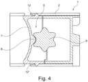
- the spring frame is not designed to be closed. Furthermore, two webs are arranged on the spring frame, approximately perpendicular to the spring frame. These webs can also deflect laterally when the shaft rotates, so that forces occurring between the cam and the ratchet wheel are absorbed by the resilient webs. This effectively prevents the spring frame from twisting in an undefined manner.
- the spring frame can be manufactured cost-effectively from plastic, particularly from a thermoplastic.
- the spring frame can expediently operate in the linear-elastic range of the material.
- the housing may also be advantageous for the housing to be made of plastic, particularly from a thermoplastic. In this case, the spring frame can be integrated into the housing in an even more cost-effective manner. The spring frame can be injected into the housing during production.
- the locking mechanism is improved in that the spring assembly is replaced by a closed spring frame, preferably made of plastic.
- the spring operates in the linear-elastic range of the material.
- the cam contour, which engages the spring is adapted to the friction pair of the spring.
- the advantages achieved by the invention are, in particular, that an exact and/or reproducible haptic can be generated for the electrical switch for a given switching function. Due to the special shape of the spring frame, it is self-centering, in particular due to the floating bearing in the housing, which reduces the influence of individual part tolerances. Likewise, the optimized friction pairing between the cam on the spring frame and the ratchet wheel eliminates the need for greasing. With the same force and/or ratchet torque ratio, the previously used number of two spring sleeves is reduced to a single spring frame in the form of a plastic spring, which results in cost savings in material and/or assembly effort.
- the closed design of the spring frame allows, depending on the switching task, either one or both cams to engage with the switching shaft. In particular, the invention allows for smaller switching angles than previously possible.
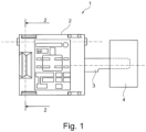
- Fig. 1 1 shows a closer look at an electrical switch 1 not according to the invention, designed as a rotary switch.
- the switch 1 has a housing 2 from which a shaft 3 protrudes.
- the shaft 3 interacts with a contact system located in the housing 2, not shown in detail, to switch the switch 1.
- An actuating element 4, which can be rotated by the user, is arranged on the shaft 3, so that the contact system can be switched into its switching positions by means of the actuating element 4.
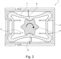
- a locking mechanism 5 interacts with the actuating member 4 in such a way that the actuating member 4 can be rotated into locking positions, the locking positions corresponding to the switching positions of the contact system correspond.
- the locking mechanism 5 consists of a ratchet wheel 6, in particular of an approximately star-shaped design, and at least one locking member 7 which exerts an elastic force and interacts with the ratchet wheel 6.
- the locking member 7 in this case consists of a spring frame. At least one cam 8 which engages in the ratchet wheel 6 is arranged on the spring frame 7.
- two cams 8, 8' each engaging in the ratchet wheel 6, are arranged opposite one another on the spring frame 7, so that the elastic ratchet force exerted by the spring frame 7 acts approximately symmetrically on the ratchet wheel 6.
- Ratchet wheels 6 are arranged, each of which interacts with a spring frame 7 as a locking mechanism 5.
- the spring frame 7 is made of plastic, in particular a thermoplastic.
- the spring frame 7 is operated in the linear-elastic range of the material.
- the housing 2 can also be made of plastic, in particular a thermoplastic.
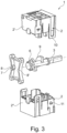
- the base 2", the cover 2', the spring frame 7, and also the shaft 3 with ratchet wheel 6 and switching cam 9 can be manufactured by injection molding.
- the cam 8, 8' can be integrated into the spring frame 7 by injection molding during the production of the spring frame 7.
- the spring frame 7 is mounted in a floating manner in the housing 2.
- the spring frame 7 can also be integrated in the housing 2, in particular in the base 2", by injecting the spring frame 7 into the housing 2 by means of injection molding during the manufacture of the housing 2.
- Such an electrical switch 1 can be used not only as a rotary switch in household appliances, such as washing machines or dishwashers, but also in other electrical devices, such as power tools.
Landscapes
- Rotary Switch, Piano Key Switch, And Lever Switch (AREA)
Claims (5)
- Commutateur électrique, en particulier commutateur rotatif, comprenant un boîtier (2), un organe d'actionnement rotatif (4), un système d'encliquetage (5) qui coopère avec l'organe d'actionnement (4) de telle sorte que l'organe d'actionnement (4) peut être amené par rotation dans des positions d'encliquetage, dans lequel l'encliquetage (5) est composé d'une roue d'encliquetage (6) en particulier configurée approximativement en forme d'étoile, ainsi que d'au moins un élément d'encliquetage (7) coopérant avec la roue d'encliquetage (6) et exerçant une force élastique, dans lequel l'élément d'encliquetage (7) est composé d'un cadre à ressort, et au moins une came (8) venant en prise avec la roue d'encliquetage (6) est disposée sur le cadre à ressort (7), le cadre à ressort (7) n'étant configuré sans être fermé ; et dans lequel deux entretoises (12, 12') sont disposées sur le cadre à ressort (7) en position approximativement verticale par rapport au cadre à ressort (7), caractérisé en ce que le cadre à ressort (7) est monté flottant dans le boîtier (2).
- Commutateur électrique selon la revendication 1, caractérisé en ce que la roue d'encliquetage (6) est disposée sur un arbre (3) en relation active avec l'organe d'actionnement (4), en ce que de préférence l'arbre (3) est monté en rotation dans le boîtier (2), en ce que de plus grande préférence, un système de contact électrique se trouve dans le boîtier (2), et dans lequel en particulier le système de contact peut être commuté au moyen d'une came de commutation (9) disposée sur l'arbre (3) dans des positions de commutation correspondant aux positions d'encliquetage.
- Commutateur électrique selon la revendication 1 ou 2, caractérisé en ce qu'en ce que deux cames (8, 8') venant respectivement en prise avec la roue d'encliquetage (6), sont disposées l'une en face de l'autre sur le cadre à ressort (7).
- Commutateur électrique selon l'une quelconque des revendications 1 à 3, caractérisé en ce que le cadre à ressort (7) est fabriqué en matière plastique, en particulier en matière plastique thermoplastique, en ce que de préférence le cadre à ressort fonctionne dans la plage élastique linéaire du matériau, et en ce que de plus grande préférence la came (8, 8') est réalisée en étant intégrée dans le cadre à ressort (7).
- Commutateur électrique selon l'une quelconque des revendications 1 à 4, caractérisé en ce que le boîtier (2) est composé de matière plastique, en particulier d'une matière plastique thermoplastique.
Applications Claiming Priority (2)
| Application Number | Priority Date | Filing Date | Title |
|---|---|---|---|
| DE102019006159.4A DE102019006159A1 (de) | 2019-09-02 | 2019-09-02 | Elektrischer Schalter |
| PCT/EP2020/072194 WO2021043529A1 (fr) | 2019-09-02 | 2020-08-06 | Commutateur électrique |
Publications (2)
| Publication Number | Publication Date |
|---|---|
| EP3837708A1 EP3837708A1 (fr) | 2021-06-23 |
| EP3837708B1 true EP3837708B1 (fr) | 2025-07-02 |
Family
ID=71994517
Family Applications (1)
| Application Number | Title | Priority Date | Filing Date |
|---|---|---|---|
| EP20753351.4A Active EP3837708B1 (fr) | 2019-09-02 | 2020-08-06 | Commutateur électrique |
Country Status (3)
| Country | Link |
|---|---|
| EP (1) | EP3837708B1 (fr) |
| DE (1) | DE102019006159A1 (fr) |
| WO (1) | WO2021043529A1 (fr) |
Citations (1)
| Publication number | Priority date | Publication date | Assignee | Title |
|---|---|---|---|---|
| DE102007013383B3 (de) * | 2007-03-16 | 2008-09-04 | Preh Gmbh | Bedienelement mit mechanischer Rastung |
Family Cites Families (7)
| Publication number | Priority date | Publication date | Assignee | Title |
|---|---|---|---|---|
| US3196237A (en) * | 1962-07-11 | 1965-07-20 | Ark Les Switch Corp | Rotary switch using plastic cover with integral leaf springs as positioning means |
| US4034178A (en) * | 1975-10-09 | 1977-07-05 | Amp Incorporated | Rotary switch housing having integral flexible detenting walls and rotor mounting structure |
| US4894492A (en) * | 1988-09-01 | 1990-01-16 | Palumbo Nicholas R | Motor control variable speed reversing switch |
| DE4430018A1 (de) * | 1994-08-24 | 1996-02-29 | Siemens Ag | Elektrische Stelleinrichtung |
| US5589671A (en) * | 1995-08-22 | 1996-12-31 | Us Controls Corp. | Rotary switch with spring stabilized contact control rotor |
| DE202008002959U1 (de) * | 2008-03-01 | 2009-07-02 | Gira Giersiepen Gmbh & Co. Kg | Elektrische Installationsvorrichtung, wie Drehschalter oder Drehregler, insbesondere Rastpotentiometer |
| JP2017091603A (ja) * | 2015-11-02 | 2017-05-25 | 株式会社村田製作所 | 回転エンコーダ |
-
2019
- 2019-09-02 DE DE102019006159.4A patent/DE102019006159A1/de active Pending
-
2020
- 2020-08-06 WO PCT/EP2020/072194 patent/WO2021043529A1/fr not_active Ceased
- 2020-08-06 EP EP20753351.4A patent/EP3837708B1/fr active Active
Patent Citations (1)
| Publication number | Priority date | Publication date | Assignee | Title |
|---|---|---|---|---|
| DE102007013383B3 (de) * | 2007-03-16 | 2008-09-04 | Preh Gmbh | Bedienelement mit mechanischer Rastung |
Also Published As
| Publication number | Publication date |
|---|---|
| DE102019006159A1 (de) | 2021-03-04 |
| EP3837708A1 (fr) | 2021-06-23 |
| WO2021043529A1 (fr) | 2021-03-11 |
Similar Documents
| Publication | Publication Date | Title |
|---|---|---|
| DE2826721C2 (fr) | ||
| EP0609672A2 (fr) | Interrupteur de sécurité | |
| DE102011087829A1 (de) | Rastvorrichtung für ein rotatorisch oder translatorisch bewegbares Bedienelement | |
| EP3837708B1 (fr) | Commutateur électrique | |
| EP1612103B1 (fr) | Dispositif avec jeu optimal pour la réception d'une part mobile d'un interrupteur | |
| WO2011045214A1 (fr) | Commutateur de puissance, en particulier pour basses tensions | |
| EP0936643B1 (fr) | Ensemble interrupteur rotatif pour appareils de ménage électriques | |
| DE60030934T2 (de) | Anordnung zur verstärkung des hubs eines betätigungsorgans eines schalters | |
| DE10037142B4 (de) | Elektrisches Schaltelement | |
| DE10025471C2 (de) | Wasserdichter Hebelschalter | |
| EP1482527B1 (fr) | Interrupteur à bouton poussoir | |
| EP1960857A1 (fr) | Commutateur a plusieurs niveaux | |
| EP2972644B1 (fr) | Unité d'entrée pour un élément de commande pouvant être actionné par pression et par rotation | |
| EP0337927B1 (fr) | Commutateur de gamme, en particulier pour un relais temporisé | |
| DE4328030C2 (de) | Elektrischer Drehschalter | |
| EP0502394B1 (fr) | Configuration des contacts | |
| DE102024138996B3 (de) | Elektrisches Schaltgerät mit formgefedertem Druckstück | |
| DE29609204U1 (de) | Kraftfahrzeug-Türschloß o.dgl. mit Kunststoff-Gehäuseteil | |
| DE10321857B4 (de) | Elektrischer Schalter | |
| EP1686600A2 (fr) | Commutateur bipolaire | |
| DE102005018144B4 (de) | Elektrische Schalteranordnung | |
| DE102005013471A1 (de) | Verschluß für ein Hausgerät | |
| DE102017203810B4 (de) | Bedieneinrichtung für ein Elektrogerät und Elektrogerät | |
| EP4119848A1 (fr) | Dispositif de commande d'un appareil électroménager et appareil électroménager | |
| DE102009005283B4 (de) | Druck- und drehbetätigbares Bedienelement für ein Kraftfahrzeug |
Legal Events
| Date | Code | Title | Description |
|---|---|---|---|
| STAA | Information on the status of an ep patent application or granted ep patent |
Free format text: STATUS: UNKNOWN |
|
| STAA | Information on the status of an ep patent application or granted ep patent |
Free format text: STATUS: THE INTERNATIONAL PUBLICATION HAS BEEN MADE |
|
| PUAI | Public reference made under article 153(3) epc to a published international application that has entered the european phase |
Free format text: ORIGINAL CODE: 0009012 |
|
| STAA | Information on the status of an ep patent application or granted ep patent |
Free format text: STATUS: REQUEST FOR EXAMINATION WAS MADE |
|
| 17P | Request for examination filed |
Effective date: 20210318 |
|
| AK | Designated contracting states |
Kind code of ref document: A1 Designated state(s): AL AT BE BG CH CY CZ DE DK EE ES FI FR GB GR HR HU IE IS IT LI LT LU LV MC MK MT NL NO PL PT RO RS SE SI SK SM TR |
|
| DAV | Request for validation of the european patent (deleted) | ||
| DAX | Request for extension of the european patent (deleted) | ||
| STAA | Information on the status of an ep patent application or granted ep patent |
Free format text: STATUS: EXAMINATION IS IN PROGRESS |
|
| 17Q | First examination report despatched |
Effective date: 20230714 |
|
| GRAP | Despatch of communication of intention to grant a patent |
Free format text: ORIGINAL CODE: EPIDOSNIGR1 |
|
| STAA | Information on the status of an ep patent application or granted ep patent |
Free format text: STATUS: GRANT OF PATENT IS INTENDED |
|
| INTG | Intention to grant announced |
Effective date: 20250408 |
|
| GRAS | Grant fee paid |
Free format text: ORIGINAL CODE: EPIDOSNIGR3 |
|
| GRAA | (expected) grant |
Free format text: ORIGINAL CODE: 0009210 |
|
| STAA | Information on the status of an ep patent application or granted ep patent |
Free format text: STATUS: THE PATENT HAS BEEN GRANTED |
|
| P01 | Opt-out of the competence of the unified patent court (upc) registered |
Free format text: CASE NUMBER: APP_20195/2025 Effective date: 20250428 |
|
| AK | Designated contracting states |
Kind code of ref document: B1 Designated state(s): AL AT BE BG CH CY CZ DE DK EE ES FI FR GB GR HR HU IE IS IT LI LT LU LV MC MK MT NL NO PL PT RO RS SE SI SK SM TR |
|
| REG | Reference to a national code |
Ref country code: GB Ref legal event code: FG4D Free format text: NOT ENGLISH |
|
| REG | Reference to a national code |
Ref country code: CH Ref legal event code: EP |
|
| REG | Reference to a national code |
Ref country code: DE Ref legal event code: R096 Ref document number: 502020011347 Country of ref document: DE |
|
| REG | Reference to a national code |
Ref country code: IE Ref legal event code: FG4D Free format text: LANGUAGE OF EP DOCUMENT: GERMAN |
|
| PGFP | Annual fee paid to national office [announced via postgrant information from national office to epo] |
Ref country code: GB Payment date: 20250820 Year of fee payment: 6 |
|
| PGFP | Annual fee paid to national office [announced via postgrant information from national office to epo] |
Ref country code: FR Payment date: 20250829 Year of fee payment: 6 |
|
| REG | Reference to a national code |
Ref country code: NL Ref legal event code: MP Effective date: 20250702 |
|
| PG25 | Lapsed in a contracting state [announced via postgrant information from national office to epo] |
Ref country code: PT Free format text: LAPSE BECAUSE OF FAILURE TO SUBMIT A TRANSLATION OF THE DESCRIPTION OR TO PAY THE FEE WITHIN THE PRESCRIBED TIME-LIMIT Effective date: 20251103 |
|
| PG25 | Lapsed in a contracting state [announced via postgrant information from national office to epo] |
Ref country code: NL Free format text: LAPSE BECAUSE OF FAILURE TO SUBMIT A TRANSLATION OF THE DESCRIPTION OR TO PAY THE FEE WITHIN THE PRESCRIBED TIME-LIMIT Effective date: 20250702 |
|
| PG25 | Lapsed in a contracting state [announced via postgrant information from national office to epo] |
Ref country code: IS Free format text: LAPSE BECAUSE OF FAILURE TO SUBMIT A TRANSLATION OF THE DESCRIPTION OR TO PAY THE FEE WITHIN THE PRESCRIBED TIME-LIMIT Effective date: 20251102 |
|
| PGFP | Annual fee paid to national office [announced via postgrant information from national office to epo] |
Ref country code: DE Payment date: 20251028 Year of fee payment: 6 |
|
| PG25 | Lapsed in a contracting state [announced via postgrant information from national office to epo] |
Ref country code: NO Free format text: LAPSE BECAUSE OF FAILURE TO SUBMIT A TRANSLATION OF THE DESCRIPTION OR TO PAY THE FEE WITHIN THE PRESCRIBED TIME-LIMIT Effective date: 20251002 |
|
| REG | Reference to a national code |
Ref country code: LT Ref legal event code: MG9D |
|
| PG25 | Lapsed in a contracting state [announced via postgrant information from national office to epo] |
Ref country code: FI Free format text: LAPSE BECAUSE OF FAILURE TO SUBMIT A TRANSLATION OF THE DESCRIPTION OR TO PAY THE FEE WITHIN THE PRESCRIBED TIME-LIMIT Effective date: 20250702 |
|
| PG25 | Lapsed in a contracting state [announced via postgrant information from national office to epo] |
Ref country code: HR Free format text: LAPSE BECAUSE OF FAILURE TO SUBMIT A TRANSLATION OF THE DESCRIPTION OR TO PAY THE FEE WITHIN THE PRESCRIBED TIME-LIMIT Effective date: 20250702 |
|
| PG25 | Lapsed in a contracting state [announced via postgrant information from national office to epo] |
Ref country code: GR Free format text: LAPSE BECAUSE OF FAILURE TO SUBMIT A TRANSLATION OF THE DESCRIPTION OR TO PAY THE FEE WITHIN THE PRESCRIBED TIME-LIMIT Effective date: 20251003 |
|
| PG25 | Lapsed in a contracting state [announced via postgrant information from national office to epo] |
Ref country code: CZ Free format text: LAPSE BECAUSE OF FAILURE TO SUBMIT A TRANSLATION OF THE DESCRIPTION OR TO PAY THE FEE WITHIN THE PRESCRIBED TIME-LIMIT Effective date: 20250702 Ref country code: SE Free format text: LAPSE BECAUSE OF FAILURE TO SUBMIT A TRANSLATION OF THE DESCRIPTION OR TO PAY THE FEE WITHIN THE PRESCRIBED TIME-LIMIT Effective date: 20250702 |
|
| PG25 | Lapsed in a contracting state [announced via postgrant information from national office to epo] |
Ref country code: LV Free format text: LAPSE BECAUSE OF FAILURE TO SUBMIT A TRANSLATION OF THE DESCRIPTION OR TO PAY THE FEE WITHIN THE PRESCRIBED TIME-LIMIT Effective date: 20250702 |
|
| PG25 | Lapsed in a contracting state [announced via postgrant information from national office to epo] |
Ref country code: PL Free format text: LAPSE BECAUSE OF FAILURE TO SUBMIT A TRANSLATION OF THE DESCRIPTION OR TO PAY THE FEE WITHIN THE PRESCRIBED TIME-LIMIT Effective date: 20250702 Ref country code: BG Free format text: LAPSE BECAUSE OF FAILURE TO SUBMIT A TRANSLATION OF THE DESCRIPTION OR TO PAY THE FEE WITHIN THE PRESCRIBED TIME-LIMIT Effective date: 20250702 |
|
| PG25 | Lapsed in a contracting state [announced via postgrant information from national office to epo] |
Ref country code: RS Free format text: LAPSE BECAUSE OF FAILURE TO SUBMIT A TRANSLATION OF THE DESCRIPTION OR TO PAY THE FEE WITHIN THE PRESCRIBED TIME-LIMIT Effective date: 20251002 |
|
| PG25 | Lapsed in a contracting state [announced via postgrant information from national office to epo] |
Ref country code: ES Free format text: LAPSE BECAUSE OF FAILURE TO SUBMIT A TRANSLATION OF THE DESCRIPTION OR TO PAY THE FEE WITHIN THE PRESCRIBED TIME-LIMIT Effective date: 20250702 |
|
| PG25 | Lapsed in a contracting state [announced via postgrant information from national office to epo] |
Ref country code: RO Free format text: LAPSE BECAUSE OF FAILURE TO SUBMIT A TRANSLATION OF THE DESCRIPTION OR TO PAY THE FEE WITHIN THE PRESCRIBED TIME-LIMIT Effective date: 20250702 |
|
| REG | Reference to a national code |
Ref country code: CH Ref legal event code: H13 Free format text: ST27 STATUS EVENT CODE: U-0-0-H10-H13 (AS PROVIDED BY THE NATIONAL OFFICE) Effective date: 20260324 |
|
| PG25 | Lapsed in a contracting state [announced via postgrant information from national office to epo] |
Ref country code: SM Free format text: LAPSE BECAUSE OF FAILURE TO SUBMIT A TRANSLATION OF THE DESCRIPTION OR TO PAY THE FEE WITHIN THE PRESCRIBED TIME-LIMIT Effective date: 20250702 |
|
| PG25 | Lapsed in a contracting state [announced via postgrant information from national office to epo] |
Ref country code: DK Free format text: LAPSE BECAUSE OF FAILURE TO SUBMIT A TRANSLATION OF THE DESCRIPTION OR TO PAY THE FEE WITHIN THE PRESCRIBED TIME-LIMIT Effective date: 20250702 |
|
| PG25 | Lapsed in a contracting state [announced via postgrant information from national office to epo] |
Ref country code: LU Free format text: LAPSE BECAUSE OF NON-PAYMENT OF DUE FEES Effective date: 20250806 Ref country code: IT Free format text: LAPSE BECAUSE OF FAILURE TO SUBMIT A TRANSLATION OF THE DESCRIPTION OR TO PAY THE FEE WITHIN THE PRESCRIBED TIME-LIMIT Effective date: 20250702 |
|
| PG25 | Lapsed in a contracting state [announced via postgrant information from national office to epo] |
Ref country code: CH Free format text: LAPSE BECAUSE OF NON-PAYMENT OF DUE FEES Effective date: 20250831 |
|
| PG25 | Lapsed in a contracting state [announced via postgrant information from national office to epo] |
Ref country code: EE Free format text: LAPSE BECAUSE OF FAILURE TO SUBMIT A TRANSLATION OF THE DESCRIPTION OR TO PAY THE FEE WITHIN THE PRESCRIBED TIME-LIMIT Effective date: 20250702 Ref country code: SK Free format text: LAPSE BECAUSE OF FAILURE TO SUBMIT A TRANSLATION OF THE DESCRIPTION OR TO PAY THE FEE WITHIN THE PRESCRIBED TIME-LIMIT Effective date: 20250702 |