EP1402100B1 - Procede et dispositif pour le traitement d'une masse fibreuse - Google Patents
Procede et dispositif pour le traitement d'une masse fibreuse Download PDFInfo
- Publication number
- EP1402100B1 EP1402100B1 EP02745240A EP02745240A EP1402100B1 EP 1402100 B1 EP1402100 B1 EP 1402100B1 EP 02745240 A EP02745240 A EP 02745240A EP 02745240 A EP02745240 A EP 02745240A EP 1402100 B1 EP1402100 B1 EP 1402100B1
- Authority
- EP
- European Patent Office
- Prior art keywords
- press
- treatment fluid
- roll
- fibre mass
- pressing
- Prior art date
- Legal status (The legal status is an assumption and is not a legal conclusion. Google has not performed a legal analysis and makes no representation as to the accuracy of the status listed.)
- Expired - Lifetime
Links
Images





Classifications
-
- D—TEXTILES; PAPER
- D06—TREATMENT OF TEXTILES OR THE LIKE; LAUNDERING; FLEXIBLE MATERIALS NOT OTHERWISE PROVIDED FOR
- D06B—TREATING TEXTILE MATERIALS USING LIQUIDS, GASES OR VAPOURS
- D06B23/00—Component parts, details, or accessories of apparatus or machines, specially adapted for the treating of textile materials, not restricted to a particular kind of apparatus, provided for in groups D06B1/00 - D06B21/00
- D06B23/02—Rollers
- D06B23/025—Perforated rollers
-
- D—TEXTILES; PAPER
- D06—TREATMENT OF TEXTILES OR THE LIKE; LAUNDERING; FLEXIBLE MATERIALS NOT OTHERWISE PROVIDED FOR
- D06B—TREATING TEXTILE MATERIALS USING LIQUIDS, GASES OR VAPOURS
- D06B1/00—Applying liquids, gases or vapours onto textile materials to effect treatment, e.g. washing, dyeing, bleaching, sizing or impregnating
- D06B1/10—Applying liquids, gases or vapours onto textile materials to effect treatment, e.g. washing, dyeing, bleaching, sizing or impregnating by contact with a member carrying the treating material
- D06B1/14—Applying liquids, gases or vapours onto textile materials to effect treatment, e.g. washing, dyeing, bleaching, sizing or impregnating by contact with a member carrying the treating material with a roller
- D06B1/16—Applying liquids, gases or vapours onto textile materials to effect treatment, e.g. washing, dyeing, bleaching, sizing or impregnating by contact with a member carrying the treating material with a roller the treating material being supplied from inside the roller
-
- D—TEXTILES; PAPER
- D06—TREATMENT OF TEXTILES OR THE LIKE; LAUNDERING; FLEXIBLE MATERIALS NOT OTHERWISE PROVIDED FOR
- D06B—TREATING TEXTILE MATERIALS USING LIQUIDS, GASES OR VAPOURS
- D06B3/00—Passing of textile materials through liquids, gases or vapours to effect treatment, e.g. washing, dyeing, bleaching, sizing, impregnating
- D06B3/02—Passing of textile materials through liquids, gases or vapours to effect treatment, e.g. washing, dyeing, bleaching, sizing, impregnating of fibres, slivers or rovings
Definitions
- the invention relates to a method for treating a fiber mass, such as a woven fabric or a nonwoven, in which the fiber mass is passed through a press shop in which the fiber mass is pressed in at least one press zone through the press jacket surface of at least one press roll by means of a pressing pressure acting on the fiber mass and the pressed fiber mass is impregnated with a treatment fluid, wherein the fiber mass in the press zone is passed through an expansion region in which the pressing pressure in the passage direction of the fiber mass decreases.
- a fiber mass such as a woven fabric or a nonwoven
- the invention also relates to a press roll arrangement for treating a fiber mass moving relative to the press roll arrangement, comprising a press roll having a press shell surface, in which a pressing pressure acting on the fiber mass is produced in operation in a press zone, and an impregnation device, by means of which in operation a treatment fluid the fiber mass is supplied, wherein in operation, the pressing zone forms an expansion region in which the pressing pressure decreases in the direction of movement of the fiber mass.
- press surface is that surface which, as an imaginary or actual lateral surface, delimits the press zone to the upper or lower side of the fiber mass, that is to say the idealized outer surface over which the pressing pressure acts on the fiber mass.
- a polymeric mass is usually melted or dissolved in a solvent and then drawn through spinners into continuous filaments.
- various spinning processes such as dry, wet spinning or a combination of dry and wet spinning are possible.
- the filaments are produced in a spinning machine and deducted from this by means of one or more take-off members, wherein they are simultaneously formed into filament bundles or cables. Thereafter, the filaments are washed in further processing steps and post-treated.
- the cable drawn from the spinning machine is fed from parallel endless filaments to a cutting device. After leaving the cutting device, a nonwoven fabric is generally formed from the individual staple fibers and deposited on a transport device for further processing.
- the stacks are produced by stack cutting machines, for example, by dry cutting through the machine described in "Ullman Volume 11, Fasem Manufacturing Process", pages 249-289.
- Viscose fibers are spun as cellulosic Regeneratfasem usually in aqueous media.
- a cutting machine consisting essentially of a pair of rollers for the supply of the tow to the cutting apparatus, the actual cutting apparatus and a Stapetfaserabschwemmvorraum.
- the cutting apparatus pulls the cable supplied by the trigger member by means of a water jet injector to the horizontally rotating cutting blades.
- the cutting blades remain edged during the cutting process by continuous regrinding.
- by the water jet supply takes place a first resolution of the staple fiber packages resulting from the cutting process prior to the flooding of the staple fiber packets on the aftertreatment machine.
- Such a machine is, for example, the company lng. A. Maurer S.A.
- the aftertreatment of, for example, viscose fibers can or must take place over several treatment steps.
- the following treatment steps are typically carried out with the supply of a treatment fluid: deacidification, desulphurization, washing, bleaching and washing, antichlorine treatment, water washing and application of lubricant or a grease support.
- These treatment steps are usually carried out in a device to which the cut staple fiber, also referred to as "flake", passes from the cutting machine via a Einschwemmvoriques to form a uniformly distributed non-woven pad.
- the device for the treatment of the fiber mass is conventionally designed as a long aggregate, in which the fiber mass distributed in a uniform fleece or fiber mass is conveyed through the individual treatment zone on a transport device.
- a belt conveyor with, for example, an endless wire belt or an endless wire belt belt, a vibrating conveyor or an eccentric detent conveyor can be used as the transport device.
- the treatment fluid from the preceding treatment step was removed as completely as possible from the fiber mass.
- a press roll arrangement which exerts a pressing pressure on the pulp. By pressing the treatment fluid is pressed out of the pulp. In the subsequent treatment step, the pressed fiber mass is then impregnated with the treatment fluid associated with this treatment step. Thus, two successive treatment steps are separated from one another by the press roller arrangement.
- the press zone In the area in which the pressing pressure acts on the fiber mass, i.
- the press zone shortly after the point of highest pressing pressure forms an area in which decreases in the conveying direction of the fiber mass of the pressing pressure. This area is called an expansion area.
- the fiber mass In order to wet the fiber mass with the treatment fluid, conventionally the fiber mass is guided on a transport device below irrigation pans. Immediately after pressing, the treatment fluid is applied to the pulp dripped by overlying sprinklers.
- DE-A-2 031 475 a device is shown in which fiber material is guided on a water-permeable belt of a conveyor and treated by liquid jets. After the treatment by the liquid jets, the fiber material is pressed out by rolling, then treated again by liquid jets and again pressed out by rolling.
- the dripping of the treatment fluid causes only uneven impregnation and wetting of the just pressed fiber mass.
- a spinning solution containing water, cellulose and tertiary amine oxide is extruded into an endless filament and stretched.
- the filament and staple fibers produced by the NMMO or lyocell method have a high crystallinity or orientation of the cellulosic molecules. Due to these product properties originating from the manufacturing process, Lyocell fibers tend to fibrillate. Fibrillation means that small fibrils separate due to the strong crystallinity and orientation of the circular fiber surface of a single fiber. Fibril formation continues along the fiber axis.
- the fiber may be treated with chemical crosslinkers which bind the fibrillar elements to the fiber stem.
- chemical crosslinkers which bind the fibrillar elements to the fiber stem.
- a crosslinking process is controlled so that the cellulosic fiber cable is impregnated with a chemical crosslinking agent and the crosslinking reaction is initiated by damping at higher temperatures.
- the crosslinking agents must be introduced homogeneously into the fiber mass after fiber production, the fiber optionally tempered and washed out of the fiber in subsequent treatment steps. In addition, like other non-cellulosic fibers, the cellulosic fiber must be cured and dried.
- the crosslinking agents tend to spontaneous chemical degradation or hydrolysis reactions, since the chemicals hydrolyze in an aqueous medium or are not stable for a long time. If the reaction parameters - for example, the reaction rate or the reaction temperature - can not be maintained exactly, it can also lead to degradation and decomposition reactions. Therefore, the crosslinking agent must be introduced in closed areas under the most precise possible control of the course of the reaction. Usually, the crosslinking agents require rapid introduction into the cellulose fiber followed by rapid tempering and subsequent as fast as possible leaching of the residual chemicals with simultaneous cooling. During so-called crosslinking, elevated temperatures and basic or acidic liquids act on the pulp.
- the chemical reaction of the cellulose with the crosslinker proceeds at elevated pH values (for example, about 11-14), thereby causing hydrolysis of the crosslinking agent.
- the decomposition tendency of the crosslinker can be suppressed by the lowest possible temperatures in the crosslinking bath.
- the low temperatures can be adjusted in or in front of the squeezing device.
- the conventional method and apparatus in which the squeezed fiber mass is merely sprinkled with a treatment fluid, is insufficient to precisely control the process parameters, especially with chemically reactive or disintegrating treatment fluids, such as crosslinkers.
- the object of the invention is therefore to improve the method mentioned at the beginning or the apparatus mentioned at the outset in such a way that the distribution of the treatment fluid, the tempering agent (hot water, superheated steam) is as fast and homogeneous as possible and possibly other heat transfer media) as well as various washing media in the fiber mass and thus an exact process control is possible.
- the tempering agent hot water, superheated steam
- the press roll arrangement has openings in the expansion region, through which the treatment fluid is conducted through the press jacket surface into the fiber mass during operation.
- This solution is simple and has the advantage that the treatment fluid is very quickly and homogeneously distributed in the pressed and compacted and relaxing in the expansion zone fiber mass. Since in the expansion region the pressing pressure decreases in the direction of movement of the fiber mass, in this region the fiber mass sucks the treatment fluid automatically through the press jacket surface. Thus, a uniform and rapid penetration of the pressed fiber mass with the treatment fluid already takes place in the press zone. This makes the treatment process more controllable and easier to control.
- the solution according to the invention has the further advantage that the overall length of a treatment machine can be significantly shortened.
- the inventive solution due to the immediate penetration of the next treatment step directly to the Impregnate the pulp with the treatment fluid connect.
- the fiber mass can be transported by means of a separate conveyor, for example in the form of a conveyor belt through the press zone, wherein the press roller rotates passively.
- the press roller can also be provided with its own drive means. In this case, can be dispensed with a separate funding, since the press roll itself forms the funding.
- the peripheral speeds of the press roll can be between 0.1 and 400 m / min, preferably between 0.1 and 60 m / min, in particular between 0.1 and 10 m / min. With these peripheral speeds, a fiber throughput of 10 to 1500 kg / (m 2 h), preferably between 10 and 1200 kg / (m 2 h) can be achieved in a treatment zone.
- the fiber throughput is calculated from the weight of the fiber mass in the absolutely dry state divided by the residence time per treatment field and is dependent on the length of the treatment field.
- the fiber mass in the pressing zone can be passed through a compression region in which the pressing pressure in the direction of passage of the fiber mass increases, so that a treatment fluid already present in the fiber mass is pressed off.
- the pressed-off treatment fluid can be discharged from the fiber mass through the pressed mantle surface.
- a suction device can be provided, through which the treatment fluid is sucked out of the compression area during operation.
- the line pressure with which a press roll according to the invention is pressed into the fiber mass is up to 100 N per mm roll width.
- treatment fluid in the compression zone for rinsing out the fiber mass can also be passed through the press shell surface before it is pressed into the fiber mass.
- the pulp in the compression zone are flushed out with the supplied in the expansion zone of the upstream press roll treatment fluid, so that no treatment fluid from the treatment step, which is arranged in the transport or conveying direction of the fiber mass through the device in front of the compression zone, are entrained in the treatment step, in the conveying direction behind the expansion zone is arranged.
- a thorough and uniform impregnation of the fiber mass with the treatment fluid can then be achieved if, according to a further advantageous embodiment, the treatment fluid is pressed under pressure, for example through nozzles arranged in the compression region into the fiber mass in the compression and / or expansion region.
- the liquid throughput based on the press roll width may be between 0.1 and 125 m 3 / (hm), preferably between 0.1 and 50 m 3 / (hm), in particular between 0.1 and 20 m 3 / (hm).
- a particularly compact design can be achieved if the impregnating device, by means of which the treatment fluid is supplied to the fiber mass, is arranged at least in sections within the press roller.
- the treatment fluid can be conducted from the interior of the press roll through openings in the fiber mass.
- the press roller may be provided on its surface facing the fiber mass with openings through which the treatment fluid is passed into the fiber mass.
- the openings may be formed regularly or irregularly in the surface of the press roll and, for example, have a substantially nozzle-shaped cross-section.
- the degree of opening of the roll ie the ratio of the areas occupied by the openings to the total surface of the roll, can be between 1 and 95%, preferably between 3 and 90%, particularly preferably between 3 and 85%.
- the press roll can also form ribs on its surface facing the fiber mass, which form the press shell surface at least in sections and between which the treatment fluid can be introduced into the fiber mass during operation.
- these ribs may extend essentially transversely to or essentially in the direction of movement of the fiber mass.
- the ribs can be designed as a weir which counteracts a flow of the treatment fluid through the pressure roller from the compression area to the expansion zone and thus carry-over.
- the height of the ribs can be so dimensioned that in the pressing zone an upper end of a rib facing away from the fiber mass substantially between the compression region and the expansion region always above the level of the treatment fluid in the Compression area and / or expansion area protrudes.
- the press roll with spaced-apart preferably transverse to the conveying direction of the fiber mass ribs can be integrated inside the press roller according to a further advantageous embodiment spray nozzles through which the treatment fluid in operation in mist or Strahtform on the pulp preferably in the press zone is directed.
- the nozzles may also be directed to the compression region in order to dilute or displace the treatment fluid present there.
- Complete wetting of the fiber mass by the treatment fluid delivered by the spray nozzles is achieved when the spray cone of the nozzles substantially overlaps in the region of the fiber mass or in the press zone.
- the impregnation device can have an adjusting device, by means of which the size and the orientation of the outlet region of the treatment fluid in the press jacket surface are adjusted.
- the adjusting device can be configured as a covering body arranged in the press roller with a slot which covers that part of the press casing surface or the press roller through which no treatment fluid should pass.
- This cover body can, for example, as one with a longitudinal slot provided, rotatably held in the press roll tubular body be configured.
- the impregnation device can have a feed line, through which the treatment fluid is conducted from outside the press roll substantially into the expansion area during operation.
- this feed line can be arranged, at least in sections, between two ribs extending essentially in the direction of movement of the fiber mass, at least in the press zone. It is advantageous if the section of the feed line facing the press casing surface terminates substantially flush with the ribs, so that the press casing surface is as smooth as possible and offers little frictional resistance with respect to the fiber mass.
- the invention also relates to a press unit for the treatment of fiber masses, comprising at least one press roll arrangement for pressing the fiber masses and a conveying means for transporting the fiber masses through the press shop, wherein a press roll arrangement according to one of the embodiments described above is used.
- the press shop and the press roll arrangement can be operated with a fiber mass whose weight is absolutely dry per unit area between 0.1 to 20 kg / m 2 , preferably 0.1 to 10 kg / m 2 .
- fiber masses cables or heavy, thick nonwovens can be aftertreated.
- treatment fluids pure water, aqueous organic or inorganic solvents, aqueous or concentrated alkalis and acids, bleaching chemicals, spin finish or inert gases, vaporous media, heating or cooling media and solvent vapors can be used.
- the press roll can be arranged at the press shop in the press zone, a further press roll, which serves as a counter-pressure means for receiving the pressing pressure.
- This second press roll may have the same configuration as the first press roll described above.
- the fiber mass is passed between the two press rolls.
- metals or plastics can be used, the surface of which can be rubberized, polished or ground.
- the edges of the press rolls and, if appropriate, the edges of the openings and ribs arranged on the press roll should be broken.
- an extrusion solution 2 is produced.
- a suspension of dry or moist comminuted cellulose and water and / or tertiary amine oxide is formed in one or more mixers.
- the suspension is evaporated using elevated temperatures under reduced pressure so much water that a cellulose solution is used as the extrusion solution.
- an extrusion solution 2 is prepared.
- the extrusion solution contains cellulose, water and tertiary amine oxide, for example N-methylmorpholine-N-oxide (NMMO) and optionally stabilizers for thermal stabilization of the cellulose and of the solvent.
- Stabilizers can e.g. be: propyl galate or alkaline media or mixtures with each other.
- additives such as titanium dioxide, barium sulfate, graphite, carboxymethylcelluloses, polyethylene glycols, ketin, ketusan, alginic acid, polysaccharides, dyes, antibacterial chemicals, flame retardants containing phosphorus, halogens or nitrogen, activated carbon, carbon blacks or electrically conductive carbon black, silica and organic solvents as diluents, etc.
- the extrusion solution 2 is conveyed through a conduit system 4.
- a pressure equalization tank 5 is arranged, which compensates for pressure and / or volume flow fluctuations in the line system 4, so that an extrusion head 6 can be supplied continuously and uniformly with the extrusion solution 2.
- the conduit system 4 is provided with temperature control means (not shown) by means of which the temperature of the extrusion solution 2 used by way of example here can be precisely controlled, as well as with a filtration unit (not shown). This is necessary because the chemical and mechanical properties of the extrusion solution are highly temperature dependent. Thus, the viscosity of the extrusion solution 2 decreases with increasing temperature and / or increasing shear rate.
- a spontaneous exothermic reaction in the extrusion solution 2 occurs, for example, when a certain temperature is exceeded and when the extrusion solution 2 ages, preferably in dead water zones.
- the line system 4 is formed in the entire, flowed through by the high-viscosity extrusion solution range flow.
- the extrusion solution is distributed in a nozzle space on a plurality of extrusion channels 8 in the form of spinning capillaries 8.
- the spinning capillaries 8 are arranged in series, in FIG. 1 perpendicular to the plane of the drawing.
- a plurality of extrusion heads 6 may be provided, each forming a plurality of Endlosformkörpfem or in the case of the embodiment of FIG. 1 spun yarns.
- Fig. 1 for the sake of simplicity, only a spinning capillary 8 is shown.
- the spin capillary usually has an inner diameter D of less than 500 .mu.m, for special applications, the diameter may also be less than 100 .mu.m, preferably by 50 to 70 microns.
- the length L of the spinning capillary through which the extrusion solution flows is at least twice, at most 100 to 150 times the inside diameter D.
- the spinning capillary 8 is at least partially surrounded by a heating device 9, through which the wall temperature of the spinning capillary 8 can be controlled.
- the wall temperature the spinning capillary 8 is around 150 ° C during operation.
- the temperature of the spinning solution is between about 80 and 130 ° C during operation.
- the spinning capillaries 8 can also be mounted in any desired form in a carrier body which is tempered from the outside, so that high hole densities result in the extrusion head 6.
- the heating device 9 preferably extends up to the outlet opening of the extrusion channel located in the direction of flow S. As a result, the wall of the extrusion channel 8 is heated up to the extrusion channel opening.
- the extrusion solution is extruded and then exits in the form of a spun yarn 11 into an air gap 12.
- the air gap has a height H in the direction of flow S of the extrusion solution.
- air 13 is supplied to the extrusion solution from the extrusion head 6 at high speed.
- the flow direction can be guided horizontally up to the extrusion thread; the flow rate of the air 13 may be greater than the extrusion rate of the spun yarn with which the continuous molded article emerges from the extrusion channel opening.
- the continuous molded article After passing through the air gap 12, the continuous molded article enters a coagulation bath zone 14, in which it is moistened or moistened with a coagulation solution.
- the moistening can be done either by means of a spraying or wetting device (not shown), or by immersing the continuous molding 11 in the coagulation bath.
- the coagulation bath solution stabilizes the extrusion solution.
- the continuous molded article 11 is deposited on a conveying device 15 essentially without tension.
- the conveyor 15 is equipped as a shaker conveyor. Due to the reciprocating motion of the shaker conveyor 16, the continuous filaments are deposited in ordered stacks 17 on the conveyor. Due to the tension-free promotion on the conveyor 15, the continuous molded body 11 can stabilize without adverse effects on the mechanical properties of the continuous molded body 11 are exerted, as may occur, for example, by too early mechanical stress shortly after the extrusion of Endlosfonn stresses 11.
- the continuous molded article 11 is drawn off by means of a take-off unit 18 and fed via deflection or conveying devices 19 to a cutting machine 20. Via the withdrawal unit 18, the corresponding fiber parameters such as titer, strength and elongation are set.
- the continuous moldings 11 of only a part of the extrusion heads 6 or all the extrusion heads 6 are introduced in parallel.
- the cutting machine 20 there is a pair of rollers (not shown) for feeding the continuous-forming body bundles 11 of the various extrusion heads 6 to the cutting apparatus, the actual cutting apparatus (not shown) and a staple fiber exhaust apparatus (not shown).
- the cutting apparatus pulls the cable supplied by the pair of draw-off rollers by means of a water jet injector to horizontally rotating cutting blades.
- the cutting blade cuts the fiber mass to a predetermined length.
- the cutting blades remain edged during the cutting process by continuous regrinding. Due to the water jet supply, a first dissolution of the staple fiber packets produced during the cutting process takes place before the staple fiber packets are floated to form a fiber mass.
- the fiber mass 21 is formed by a random orientation of the cut in the cutting machine 20 fibers.
- the device 22 for treating the fiber mass 21 essentially forms the subject of the present invention.
- typical treatment steps are carried out for viscose fibers, such as deacidifying, desulfurizing, washing, bleaching and washing, antichlorine treatment, water washing and application of finishing / grease or other chemicals.
- the individual treatment steps or phases take place respectively in treatment zones 23, 24, 25, 26, 27, which are separated from one another by press roll arrangements 28, 29, 30, 31, 32, 33.
- an impregnating device 34, 35, 36, 37, 38 respectively supplies a treatment fluid assigned to this treatment zone or treatment step from corresponding storage containers 39, 40, 41, 42, 43.
- the treatment zones have a distance of at least approximately 0.5 m from the center of the roller to the center of the roller in the conveying direction of the fiber masses, but the decorum can be up to 10 m and more, depending on the requirement of the treatment process.
- the individual press roll arrangements 28, 29, 30, 31, 32, 33 can also follow one another directly, so that the press rolls are not touching at all.
- the reservoirs 39 to 43 are supplied in countercurrent with treatment fluid, i. the treatment fluid from a subsequent step in the direction of conveyance B of the pulp 21 is supplied to a treatment step preceding it in a substantially untreated treatment step; the direction of the flow of the treatment fluid through the device 22 is opposite to the conveying direction of the fiber mass 21 through the device 22. In the conveying direction B, therefore, the purity of the treatment fluid in the Vorrats actuallyem 39 to 43, which are arranged as a collecting container under the pulp 21, to.
- the fiber mass 21 is transported by the device 22 on a conveyor 44, which may be designed as a belt conveyor with an endless wire belt or Drahtgewebegurt, as a vibrating conveyor or as an eccentric detent conveyor.
- the press roll arrangements 28 to 33 can, as shown in FIG. 1, be designed either as paired rolls or as standalone rolls with a fixed counterpressure surface.
- the contact pressure of the rollers can be controlled electrically, hydraulically or pneumatically, as well as mechanically, for example by means of lever forces be generated.
- the typical contact pressure of the press roll is up to about 100 N per mm roll width.
- the treatment fluid introduced into the respective treatment zone 23 to 27 is pressed out of the fiber mass and the carry-over of the treatment fluid from a preceding treatment step to the next treatment step is prevented.
- the fiber mass 21 can be supplied to further, not shown in Fig. 1 treatment steps.
- a drying device with opening units for dehumidifying and loosening the fiber mass and a packaging unit for producing a product ready for shipment can follow.
- Fig. 1 shows an example of the production of a pulp from a cellulosic dope.
- the use of the device 22 is not limited to cellulosic fibers, but may also be used on nonwoven or interwoven fiber masses of filaments of other composition.
- nonwoven or interwoven fiber masses of filaments of other composition For the production of such fiber masses from non-viscous or non-cellulosic fibers, other production methods are known from the prior art.
- press roll arrangement will be described by way of example. Since the basic function of the press roll arrangements 28 to 33 is the same in each case, in the following description, only a single press roll arrangement will be described by way of example.
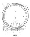
- FIG 2 shows a first exemplary embodiment of a press roll arrangement 50 according to the invention for treating the fiber mass 21 in a section perpendicular to the direction of movement B of the fiber mass 21.
- the press roll arrangement shown in Fig. 2 is used for cable washing or staple fiber washing at low speeds and large pulps, with the pulp moving in the conveying direction at a speed of about 40 m / min. This speed corresponds to the extrusion speed of the Endless shaped body on the extrusion head.
- the fiber throughput is about 52 kg / (m 2 h), wherein the treatment fluid is supplied at a flow rate of 125 m 3 / (hm) per m roll width.
- the press roll assembly 50 has a press roll 51, which is rotatably mounted on a bearing, not shown in FIG. 2 and rotates in the direction of arrow P with the movement of the fiber mass 21.
- the press roll 51 is pressed into the pulp 21 with a contact force F.
- a press jacket surface 52 forms, which is the imaginary envelope surface around the press roll 51, through which the pressing pressure generated by the press force F acts on the fiber mass 21.
- pressing zone 53 The area over which the pressing force F acts on the fiber mass 21 as pressing pressure via the press mantle surface 52 is referred to as pressing zone 53.
- the pressing pressure first increases in the pressing zone up to approximately the area in which the press roll 51 penetrates the fiber mass 21 lowest.
- the area of the pressing pressure increasing in the direction of movement B of the fiber mass is referred to below as the compression area 54.
- An expansion area 55 adjoins the compression area 54 in the direction of movement B of the fiber mass 21, in which the pressing pressure in the direction of movement B of the fiber mass decreases again.
- the first treatment fluid 56 received in the fiber mass 21 is pressed off in the compression zone 54, so that virtually no first treatment fluid 56 from the preceding treatment step is present in the fiber mass 21 after the compression zone 54.
- the press roller 51 is provided with through holes 57 extending from the inside of the press roller to the outside of the press roller.
- the through openings 57 terminate in recesses 58 whose diameter is greater than the diameter of the through openings 57.
- the recesses can also be slit-shaped along the press roll axis and distributed over the circumference.
- the diameter of the holes is at a roll diameter of 400 mm at 3 to 12 mm.
- the degree of opening of the press roll 51 is, largely independent of its diameter, at about 5 to 40%.
- the through-holes 57 may be randomly distributed, arranged in rows in the axial direction or in the circumferential direction or offset from each other on the outer circumferential surface 59.
- the interior of the press roll forms part of an impregnating device, is introduced through the second treatment fluid into the fiber mass.
- a cover body 60 is provided, which is designed substantially tubular and has an opening 61 extending in the axial direction of the press roll 51 in the form of a slot which faces the press zone.
- the cover body 60 does not move with the press roller 51, but is stationary.
- the covering body 60 is respectively provided with sealing elements 62, so that no second treatment fluid can pass from the interior 63 of the pressing roller 51 between the covering body 60 and the inner circumferential surface 64 of the pressing roller 51.
- the covering body 60 serves to delimit the region 65, via which second treatment fluid is introduced into the fiber mass 21.
- the region 65 extends mainly into the region of the expansion zone 55, but also-at least in sections-into the region of the compression zone 54. If from the interior 63 of the press roll 51 second treatment fluid, for example under a pressure of 2, 5 to 3 bar, is passed through the through-holes 57, this second treatment fluid in the compression zone 54, the first psychologistssunasfluid 56, shown schematically in Fig. 2, rinse from the previous treatment step and at the same time it is in the expansion zone 55 by the Capillary action and swelling of the pulp 21 absorbed due to the decreasing pressure.
- second treatment fluid for example under a pressure of 2, 5 to 3 bar
- the first cover body 60 coaxially held in the pressure roller 51 about its longitudinal axis X pivotally, as indicated by the double arrow A.
- FIG. 3 shows a development of the embodiment of FIG. 2. In the following, only the differences from the exemplary embodiment of FIG. 2 will be discussed.
- the press roll arrangement of FIG. 3 may be used as a pulp 21 for washing a cellulosic nonwoven having a weight of about 4.1 kg / m 2 .
- the fiber mass is moved at a speed of about 0.1 m / min in the conveying direction.
- the fiber throughput per meter roll width is around 40 kg / (hm 2 ) in such an application.
- the treatment fluid is supplied at a rate of 0.7 m 3 / (hm).
- the cover body in the development of FIG. 3 in two cover body 60 a and 60 b is divided into two.
- Each of the two covering bodies 60a, 60b is held pivotable about the longitudinal axis X independently of the other covering body on the inner peripheral surface 64 of the pressing roller 51.
- both the opening angle ⁇ and the orientation of the slot 61 can be changed by adjusting a covering body 60a, 60b or both covering bodies 60a, 60b.
- a sealing body 66 which covers a movement slot 67, which is likewise formed by the two cover bodies 60a, 60b and ensures the mobility of the two cover bodies 60a, 60b against one another.
- the sealing body 66 may be arranged within the cover body 60a, 60b or, in an attemative embodiment, between cover body 60a, 60b and press roller 51.
- the tubular, provided with a longitudinal slot sealing body 66 is provided with sealing elements 68, which prevent penetration of treatment fluid between the cover body and sealing body.
- Fig. 3 can be made by the great variability in size and location of the treatment zone 65, a precise adaptation to the respective treatment step and the wetting requirements of the supplied in this treatment step the second treatment fluid.
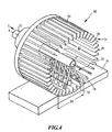
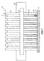
- FIG. 4 A second embodiment of a press roll arrangement according to the invention is shown in FIG. 4.
- the same reference numerals are used for elements whose structure or function substantially correspond to the elements of the preceding embodiment.
- the pressure roller 51 is formed of a plurality of extending in the axial direction X of the pressure roller 51 ribs 70.
- the ribs have a wall thickness which increases in the radial direction from the inside of the press roll 51 to the outside.
- the ribs 70 On their outer side, the ribs 70 at least in sections in the press zone 53, the press shell surface 52.
- the ribs 70 are each attached to the two in the axial direction X located ends of the press shell surface of mounting disks or rings.
- the ribs 70 are all parallel to each other and are equally spaced from each other, the area 71 lying between them is substantially free of material.
- the ribs 70 can be interconnected by circumferentially extending, disc or annular struts, so that they obtain a greater mechanical stability.
- the degree of opening of the press roll 40 may be in some cases up to between 90 and 95%.
- the number of ribs is between 30 and 80, preferably around 60. With a diameter of the press roll of 400 mm, the width of the rib in the circumferential direction between 1 and 20 mm, with wider webs although a higher pressure, but a lower liquid flow rate is achievable.
- an impregnating device 72 is arranged, is passed through the treatment fluid into the interior 63 of the press roller 51.
- Such an impregnating device 72 may alternatively be used, for example, also in the embodiment of FIG. 2 instead of or together with the covering body 60.
- the impregnating device according to the embodiment of FIG. 2 or 3 can be used together with the covering body 60 described therein.
- the impregnating device 72 of the embodiment of FIG. 4 consists of a central supply line 73 which extends coaxially to the axis X of the press roller 51.
- the feed line 73 is shown cut in Fig. 4 at its end located in the axial direction X, but at its right in Fig. 4 end may also be provided an end cap, or the feed line 73 may extend through the entire press roll 51 in the axial direction X and the Apply treatment fluid to another press roller assembly.
- the end of the supply line 73 located in the direction of flow S of the treatment fluid may be connected to the inlet of the supply line 73 in order to enable a recycling of the treatment fluid in this treatment step.
- the impregnation device 72 is further provided with one or a plurality of spray nozzles 74 which are directed onto the fiber mass 21.
- the treatment fluid flows from the central supply line or the collection tube 73 through the individual nozzles 74 and between the ribs 70 into the fiber mass 21.
- FIG. 5 shows a cross section perpendicular to the axial direction X of the embodiment of FIG. 4.
- a spray cone 75 is formed by the second treatment fluid from the spray nozzles 74, wherein the spray 75 overlap each other so that in the press zone 53, no area is present, which is not wetted by the second treatment fluid ,
- the spray cones 75 may be conical or flat.
- each rib 70 is dimensioned so that the ribs located substantially in the pressing zone 53 form a weir through which a direct flow of the treatment fluid between the areas on both sides of the pressing zone is not possible.
- a spray nozzle 74 ' is directed to the compression zone to rinse any inflowing there treatment fluid 56 from the previous treatment step.
- the treatment area 65 can be adjusted in terms of size and orientation by adjusting the spray nozzles 74.
- the spacing of the ribs in the circumferential direction from each other is such that a sufficient amount of second treatment fluid can pass between the ribs and at the same time the pressing pressure in the pressing zone 53 can still act evenly on the fiber mass 21.
- Fig. 6 shows a perspective view of a third embodiment of a press roll assembly 50 according to the invention.
- the same reference numerals as in the previous embodiments are used for elements whose structure and function corresponds to an element of the preceding embodiments.
- the press roll 51 of the embodiment of FIG. 6 has in the axial direction X of the press roll 51 spaced-apart ribs 70, between which a gap 71 is formed.
- the press jaw assembly 50 further comprises two impregnating means 72a, 72b which are arranged on both sides of the pressing roller 51 with respect to the direction of movement B of the mass of fibers not shown in FIG. 6 for the sake of simplicity.
- Each impregnation device 72a, 72b has a collection tube 73 running parallel to the axial direction X of the pressure roller 51, from which supply lines 80 extend into the intermediate spaces 71 between the ribs 70 and into the pressing zone 53.
- the leads 80 of the two impregnating devices 72a and 72b are integrally connected to each other, so that the treatment fluid from the collecting pipe 73 of the impregnating device 72a to the collecting pipe 73 of the impregnating device 72b, and a part of the treatment fluid in the pressing zone 53 exits through openings of the supply lines 80 not shown in FIG.
- the supply lines 80 of the impregnation device 72a and the supply lines 80 of the impregnation device 72b can also be separated from one another, so that a different treatment fluid is conducted through the impregnation device 72a into the pressing zone 53 than through the treatment device 72b.
- a different treatment fluid is conducted through the impregnation device 72a into the pressing zone 53 than through the treatment device 72b.
- the cross-section of the supply lines 80 is designed so that it substantially corresponds to the cross section of the intermediate spaces 71 and thus largely fills the intermediate spaces 71.
- the flow S of the treatment fluid through the collecting tube 73 is passed through the supply lines 80 into the pressing zone 53. This can be seen in particular in Fig. 7, in which an end view of the embodiment of FIG. 6 in the direction of movement B of the fiber mass 21 is shown.
- FIG. 7 shows a supply line as a partial section in the region of the press zone, in particular in the region of the expansion area 55.
- the supply line has openings 81 in this area, through which the second treatment passage exits into the intermediate space 71 and enters the fiber mass 21 through the press jacket surface 52.
- the section of the supply lines 80 facing the fiber mass 21 can also come into contact with the fiber mass 21.
- special precautions with regard to surface quality and abrasion resistance of the leads 80 are to be made in order to prevent damage to the fiber mass 21 and premature wear of the leads 80 by the fiber mass 21 conveyed past under pressure.
- a drive means 82 for example, an electric motor is further shown, through which the pressure roller 51 is driven in rotation synchronously with the movement of the fiber mass.
- a drive means 82 can also be used in other embodiments.
- the press roller itself can be used as a conveyor for the pulp 21, through which the pulp 21 is transported through the individual treatment steps of the press shop.
- FIG. 8 shows a fourth exemplary embodiment of a press roll arrangement 50 according to the invention in a section parallel to the direction of movement B of the fiber mass 21 and perpendicular to the axial direction X of the press roll 51.
- the press roll arrangement 50 according to FIG. 8 has a counterpressure roll 90 which has one of the contact pressure F 1 the pressing roller 51 deeumblegestichteten pressing force F 2 of the same size is pressed into the pulp 21.
- the press roller 51 and the back pressure roller 90 both have the same structure as that of the first embodiment as shown in FIGS. 2 and 3.
- each roller 51, 90 in the pressing zone 53 can cause both suction and impregnation.
- the press roll arrangement 50 according to the invention when used at a press shop 22, the press roll arrangement responsible for the next treatment step can immediately follow because an instantaneous homogeneity due to the impregnation of the fiber mass 21 through the press mantle surface 52 Distribution of the treatment fluid in the pulp 21 takes place.
- impregnation process Due to the immediate homogeneous distribution within the fiber mass 21, which is supported by the small fiber spacing in the expansion zone 55 and the consequent capillary action, the impregnation process can be more accurately performed and controlled more easily. As a result, impregnation is also possible with critically treatable treatment fluids, which may be prone to spontaneous chemical reactions.
- rolls according to the invention can also be used elsewhere in a plant for fiber production, for example as draw-off rolls with integrated wax device.
- fiber pulps made of natural or synthetic fibers can also be treated by the device according to the invention and the process according to the invention, for example fiber pulp of viscose, acetate, polyester, polyamide and polyacrylic.
- Examples 1 to 4 of the following table a fiber cable produced by the Lyocell method is stacked by means of a wet-cutting machine and, in this state, applied as a pulp 21 to a treatment device 22. It is assumed in the weight of the fiber mass in the absolutely dry state.
- the fiber cutter is directly without prior Cutting the treatment device 22 supplied as a pulp 21.
- the treatment fluid used in all examples is water.
- the device 22 is configured in all examples 1 to 5 so that in each treatment zone, the fiber mass 21 is completely penetrated by the treatment fluid over its entire thickness.
- Example 1 the impregnation of the fiber mass according to the method of the prior art by sprinkling the fiber mass with the treatment fluid in the conveying direction behind the press roll instead.
- the fiber mass 21 is not completely penetrated immediately after the impingement of the treatment fluid, so that the treatment fluid accumulates in a kind of lake above the fiber mass and only gradually seeps through the fiber mass 21.
- This lake formation increases with increasing thickness of the fiber mass.
- a complete penetration of the fiber mass with the treatment fluid is achieved only with a longer residence time of the fiber mass in the treatment zone.
- the treatment zone in the conveying direction of the fiber mass by the treatment device must have a corresponding length.
- Example 2 the treatment is carried out with a press roll designed according to the invention with treatment conditions otherwise identical to example 1.
- Example 1 ie the solution from the prior art, the fiber throughput ie m 2 treatment zone and hour is significantly lower than in Example 2.
- the press rolls according to the invention are also used, so that the fiber mass is immediately penetrated upon contact with the liquid and long treatment fields for complete penetration of the fiber mass are not required.
- a much more uniform and faster distribution of the treatment fluid in the fiber mass the result.
Landscapes
- Engineering & Computer Science (AREA)
- Textile Engineering (AREA)
- Treatment Of Fiber Materials (AREA)
- Nonwoven Fabrics (AREA)
- Preliminary Treatment Of Fibers (AREA)
- Paper (AREA)
- Treatments For Attaching Organic Compounds To Fibrous Goods (AREA)
- Multicomponent Fibers (AREA)
Claims (44)
- Procédé de traitement d'une masse fibreuse ou masse de fibres (21), telle qu'un composite de filaments, un tissu ou un non-tissé, d'après lequel on fait passer la masse fibreuse (21) à travers un groupe de pressage (22) dans lequel la masse fibreuse (21), dans au moins une zone de pressage (53), est exprimée par la surface enveloppe de pressage (52) d'au moins un cylindre de pressage (51) au moyen d'une pression de pressage agissant sur la masse fibreuse (21), et la masse fibreuse exprimée est imprégnée d'un fluide de traitement, la masse fibreuse (21) étant menée, dans la zone de pressage (53), à travers une zone d'expansion (55) dans laquelle la pression de pressage diminue dans la direction de passage (B) de la masse fibreuse (21), caractérisé en ce que le fluide de traitement est amené dans la masse fibreuse (21), au niveau de la zone d'expansion (55), à travers la surface enveloppe de pressage (52).
- Procédé selon la revendication 1, caractérisé en ce que l'on fait passer la masse fibreuse (21), avant la zone d'expansion (55), à travers une zone de compression (54) de la zone de pressage (53), dans laquelle la pression de pressage augmente dans la direction de passage (B) de la masse fibreuse (21) et un fluide de traitement (56) déjà présent est extrait par pressage de la masse fibreuse (21).
- Procédé selon la revendication 2, caractérisé en ce que le fluide de traitement ayant été extrait par pressage est évacué dans la zone de compression (54), à travers la surface enveloppe de pressage (52).
- Procédé selon la revendication 1, caractérisé en ce que le fluide de traitement est introduit par pressage dans la masse fibreuse (21) dans la zone de compression (54).
- Procédé selon la revendication 4, caractérisé en ce que le fluide de traitement, est envoyé dans la masse fibreuse (21) dans la zone de compression (54), à travers la surface enveloppe de pressage (52).
- Procédé selon l'une des revendications précédemment citées, caractérisé en ce que l' on fait passer la masse fibreuse (21), dans la zone de pressage (53), entre au moins deux cylindres de pressage (51, 90).
- Procédé selon l'une des revendications précédemment citées, caractérisé en ce que le fluide de traitement est introduit par pressage, sous pression, dans la masse fibreuse (21).
- Procédé selon l'une des revendications précédemment citées, caractérisé en ce qu'en amont du groupe de pressage (22), on fabrique la masse fibreuse (21) avec un poids spécifique entre 0,1 et 20 kg/m2.
- Procédé selon l'une des revendications précédemment citées, caractérisé en ce que la masse fibreuse (21) est amené au groupe de pressage (22) sous forme de nappe.
- Procédé selon l'une des revendications précédemment citées, caractérisé en ce que l'on fait passer la masse fibreuse (21) successivement à travers plusieurs agencements de cylindre de pressage (28, 29, 30, 31, 32, 33) dans chacun desquels un premier fluide de traitement est extrait de la masse fibreuse (21) par pressage dans la zone de compression (54), et la masse fibreuse (21) est imprégnée avec le deuxième fluide de traitement dans la zone d'expansion (55).
- Procédé selon l'une des revendications précédemment citées, caractérisé en ce que la masse fibreuse (21) est fabriquée à partir d'une solution contenant de la cellulose, de l'eau et de l'amine-oxyde tertiaire.
- Procédé selon l'une des revendications précédemment citées, caractérisé en ce que l'on fait fonctionner le cylindre de pressage (51) avec une vitesse périphérique d'au moins 0,1 m/min.
- Agencement de cylindre de pressage (50) pour le traitement d'une masse fibreuse (21) se déplaçant par rapport à l'agencement de cylindre de pressage, comprenant au moins un cylindre de pressage (51) avec une surface enveloppe de pressage (52) par laquelle est exercée, en fonctionnement, une pression de pressage agissant sur la masse fibreuse (21) dans une zone de pressage (53), et comprenant au moins un dispositif d'imprégnation (72 ; 72a, 72b) par lequel un fluide de traitement est amené, en fonctionnement, à la masse fibreuse (21), la zone de pressage (53) réalisant, en fonctionnement, une zone d'expansion (55) dans laquelle la pression de pressage diminue dans la direction de mouvement (B) de la masse fibreuse (21), caractérisé en ce que l'agencement de cylindre de pressage (50) présente, dans la zone d'expansion (55), des ouvertures (57, 58 ; 71, 81) à travers lesquelles le fluide de traitement est envoyé, en cours de fonctionnement, dans la masse fibreuse (21), à travers la surface enveloppe de pressage (52).
- Agencement de cylindre de pressage selon la revendication 13, caractérisé en ce que le dispositif d'imprégnation (72 ; 72a, 72b) est agencé, au moins par secteurs, à l'intérieur du cylindre de pressage (51).
- Agencement de cylindre de pressage selon la revendication 13 ou 14, caractérisé en ce que le cylindre de pressage (51) forme, au niveau de sa surface (59) dirigée vers la masse fibreuse (21), des nervures (70) qui forment, au moins par secteurs, la surface enveloppe de pressage (52), et entre lesquelles le fluide de traitement peut, en cours de fonctionnement, être envoyé dans la masse fibreuse (21) à travers la surface enveloppe de pressage (52).
- Agencement de cylindre de pressage selon la revendication 15, caractérisé en ce que les nervures (70) s'étendent sensiblement transversalement à la direction de mouvement de la masse fibreuse.
- Agencement de cylindre de pressage selon la revendication 15, caractérisé en ce que les nervures (70) s'étendent sensiblement dans la direction de mouvement (B) de la masse fibreuse (21).
- Agencement de cylindre de pressage selon l'une des revendications 13 à 17, caractérisé en ce que dans le cylindre de pressage (51) sont intégrées des buses (74) par lesquelles le fluide de traitement est dirigé, en cours de fonctionnement, sur la masse fibreuse (21).
- Agencement de cylindre de pressage selon la revendication 18, caractérisé en ce que les buses (74) présentent des cônes de pulvérisation (75) qui se chevauchent mutuellement.
- Agencement de cylindre de pressage selon la revendication 18 ou 19, caractérisé en ce que les buses (74) sont disposées à l'intérieur du cylindre de pressage (51) et les cônes de pulvérisation (75) sont dirigés au travers des nervures (70).
- Agencement de cylindre de pressage selon l'une des revendications 13 à 20, caractérisé en ce que les nervures (70) sont réalisées en tant que système de barrage qui agit à l'encontre d'un écoulement du fluide de traitement à travers le cylindre de pressage (51), de la zone de compression (54) vers la zone d'expansion (55).
- Agencement de cylindre de pressage selon l'une des revendications 13 à 21, caractérisé en ce que le dispositif d'imprégnation (72 ; 72a, 72b) est pourvu d'un dispositif de réglage (60, 66 ; 78) permettant de régler la grandeur de la zone (65) de la surface enveloppe de pressage (52), à travers laquelle passe le fluide de traitement en cours de fonctionnement.
- Agencement de cylindre de pressage selon la revendication 22, caractérisé en ce que le dispositif de réglage (60, 66) est réalisé sous la forme d'un corps de recouvrement (60) disposé dans le cylindre de pressage (51, 90) et présentant une ouverture (61) associée à ladite zone (65).
- Agencement de cylindre de pressage selon la revendication 23, caractérisé en ce qu'il est prévu une mécanique de réglage grâce à laquelle il est possible de régler l'orientation et/ou la grandeur de l'ouverture (61).
- Agencement de cylindre de pressage selon l'une des revendications 13 à 24, caractérisé en ce qu'il est prévu un dispositif d'aspiration par lequel le fluide de traitement est aspiré de la zone de compression (54), en cours de fonctionnement.
- Agencement de cylindre de pressage selon l'une des revendications 13 à 25, caractérisé en ce que le dispositif d'imprégnation (72 ; 72a, 72b) comprend une conduite d'amenée (73, 80) par laquelle le fluide de traitement est mené, en cours de fonctionnement, de l'extérieur du cylindre de pressage jusque sensiblement dans la zone d'expansion (55).
- Agencement de cylindre de pressage selon la revendication 26, caractérisé en ce que la conduite d'amenée (73, 80), au moins dans la zone de pressage (53), est disposée au moins par secteurs, entre deux nervures (70) s'étendant sensiblement dans la direction de mouvement (B) de la masse fibreuse (21).
- Agencement de cylindre de pressage selon l'une des revendications 13 à 27, caractérisé en ce qu'au plus environ 95% de la surface périphérique extérieure (59) est réalisée en tant que surface de passage pour le fluide de traitement.
- Agencement de cylindre de pressage selon la revendication 28, caractérisé en ce qu'au plus environ 90% de la surface périphérique extérieure (59) est réalisée en tant que surface de passage pour le fluide de traitement.
- Agencement de cylindre de pressage selon la revendication 29, caractérisé en ce qu'au plus environ 85% de la surface périphérique extérieure (59) est réalisée en tant que surface de passage pour le fluide de traitement.
- Agencement de cylindre de pressage selon l'une des revendications 28 à 30, caractérisé en ce qu'au moins environ 1% à 3% de la surface périphérique extérieure (59) est réalisée en tant que surface de passage pour le fluide de traitement.
- Agencement de cylindre de pressage selon l'une des revendications 13 à 31, caractérisé en ce que l'on fait fonctionner le cylindre de pressage (51) avec une vitesse périphérique de moins de 400 m/min.
- Agencement de cylindre de pressage selon la revendication 32, caractérisé en ce que l'on fait fonctionner le cylindre de pressage (51) avec une vitesse périphérique de moins de 60 m/min.
- Agencement de cylindre de pressage selon la revendication 32, caractérisé en ce que l'on fait fonctionner le cylindre de pressage (51) avec une vitesse périphérique de moins de 10 m/min.
- Agencement de cylindre de pressage selon les revendications 13 à 34, caractérisé en ce que, rapporté à la largeur de cylindre, on amène entre 0,1 et 125 m3/(h m) de fluide de traitement.
- Agencement de cylindre de pressage selon la revendication 35, caractérisé en ce que, rapporté à la largeur de cylindre, on amène entre 0,1 et 50 m3/(h m) de fluide de traitement.
- Agencement de cylindre de pressage selon la revendication 35, caractérisé en ce que, rapporté à la largeur de cylindre, on amène entre 0,1 et 20 m3/(h m) de fluide de traitement.
- Groupe de pressage (22) pour le traitement de masses fibreuses (21), comprenant au moins deux agencements de cylindre de pressage (50) disposés en se succédant dans une direction de transport de la masse fibreuse, et entre lesquels est formé au moins une région de traitement dans laquelle un fluide de traitement agit sur la masse fibreuse, caractérisé en ce que l'agencement de cylindre de pressage (50) est d'une configuration selon l'une des revendications 13 à 37.
- Groupe de pressage selon la revendication 38, caractérisé en ce qu'au moins un agencement de cylindre de pressage est réalisé en tant que moyen de transport par lequel la masse fibreuse est transportée à travers le groupe de pressage.
- Groupe de pressage selon la revendication 38 ou 39, caractérisé en ce que le groupe de pressage présente au moins une paire de cylindres de pressage (51, 90) entre lesquels on fait passer la masse fibreuse (21), en cours de fonctionnement.
- Groupe de pressage selon l'une des revendications 38 à 40, caractérisé en ce que la masse fibreuse (21) présente, au cours du fonctionnement, un poids par unité de surface de 0,1 à 20 kg/m2.
- Groupe de pressage selon la revendication 41, caractérisé en ce que la masse fibreuse (21) présente, au cours du fonctionnement, un poids par unité de surface de 0,1 à 10 kg/m2.
- Groupe de pressage selon l'une des revendications 38 à 42, caractérisé en ce que le débit de masse fibreuse par région de traitement vaut environ 10 à 1500 kg/(m2 h) .
- Groupe de pressage selon la revendication 43, caractérisé en ce que le débit de masse fibreuse par région de traitement vaut environ 10 à 1200 kg/(m2 h).
Applications Claiming Priority (3)
| Application Number | Priority Date | Filing Date | Title |
|---|---|---|---|
| DE10132214 | 2001-06-30 | ||
| DE10132214A DE10132214A1 (de) | 2001-06-30 | 2001-06-30 | Verfahren und Vorrichtung zum Behandeln einer Fasermasse |
| PCT/EP2002/004316 WO2003004750A1 (fr) | 2001-06-30 | 2002-04-18 | Procede et dispositif pour le traitement d'une masse fibreuse |
Publications (2)
| Publication Number | Publication Date |
|---|---|
| EP1402100A1 EP1402100A1 (fr) | 2004-03-31 |
| EP1402100B1 true EP1402100B1 (fr) | 2006-03-15 |
Family
ID=7690452
Family Applications (1)
| Application Number | Title | Priority Date | Filing Date |
|---|---|---|---|
| EP02745240A Expired - Lifetime EP1402100B1 (fr) | 2001-06-30 | 2002-04-18 | Procede et dispositif pour le traitement d'une masse fibreuse |
Country Status (12)
| Country | Link |
|---|---|
| US (1) | US20050015889A1 (fr) |
| EP (1) | EP1402100B1 (fr) |
| KR (1) | KR100562972B1 (fr) |
| CN (1) | CN1283872C (fr) |
| AT (1) | ATE320519T1 (fr) |
| BR (1) | BR0211050A (fr) |
| CA (1) | CA2449733C (fr) |
| DE (2) | DE10132214A1 (fr) |
| MY (1) | MY135522A (fr) |
| TW (1) | TWI222478B (fr) |
| WO (1) | WO2003004750A1 (fr) |
| ZA (1) | ZA200309318B (fr) |
Families Citing this family (17)
| Publication number | Priority date | Publication date | Assignee | Title |
|---|---|---|---|---|
| DE112005000311B4 (de) * | 2004-02-05 | 2011-04-07 | Advantest Corp. | Messgerät, Messverfahren und Testgerät |
| DE102005027349A1 (de) * | 2005-06-13 | 2006-01-12 | Zimmer Ag | Verfahren und Vorrichtung zum Nachbehandeln venetzter Cellulose-Fasern mit einer Bisulfitverbindung |
| AT504649B1 (de) * | 2007-07-11 | 2008-07-15 | Chemiefaser Lenzing Ag | Vorrichtung und verfahren zur behandlung einer fasermasse |
| AT505730B1 (de) * | 2007-08-16 | 2010-07-15 | Helfenberger Immobilien Llc & | Mischung, insbesondere spinnlösung |
| CN101643983B (zh) * | 2009-09-07 | 2011-07-20 | 哈尔滨工业大学 | 纤维丝悬滴涂覆上浆方法所用的装置 |
| CN101824715B (zh) * | 2010-01-22 | 2012-05-16 | 中国人民解放军总后勤部军需装备研究所 | 一种纤维束漂洗柔软方法及装置 |
| WO2015061877A1 (fr) * | 2013-10-29 | 2015-05-07 | Braskem S.A. | Système et procédé de dosage d'un mélange d'un polymère avec un premier solvant, dispositif, système et procédé d'extraction de solvant d'au moins un fil polymère, système et procédé de pré-récupération mécanique d'au moins un liquide dans au moins un fil polymère, et système et procédé continus pour la production d'au moins un fil polymère |
| ES2858579T3 (es) * | 2015-06-11 | 2021-09-30 | Karl Mayer Stoll R&D Gmbh | Tanque para lavar un hilo de urdimbre |
| US10570542B2 (en) * | 2015-09-11 | 2020-02-25 | Teresa Catallo | Apparatus and method for pre-shrinking a wet fabric prior to drying |
| KR101953347B1 (ko) * | 2016-02-16 | 2019-05-22 | 주식회사 엘지화학 | 에어로겔 시트용 제조기 |
| CN109778463B (zh) * | 2019-01-28 | 2021-05-18 | 江苏华艺服饰有限公司 | 一种面料脱水装置的压挤式脱水结构 |
| CN112981578A (zh) * | 2019-12-12 | 2021-06-18 | 连津格股份公司 | 后处理和整理方法 |
| US20210262135A1 (en) * | 2020-02-24 | 2021-08-26 | James Catallo | Apparatus and method for pre-shrinking a wet fabric prior to drying |
| CN112252207B (zh) * | 2020-10-16 | 2022-04-15 | 辽宁交通建设集团有限公司 | 一种桥梁建筑加固纤维网加工处理系统 |
| CN114808307B (zh) * | 2022-06-28 | 2022-09-09 | 博润生物科技南通有限公司 | 一种化工溶液喷涂设备 |
| CN116590633B (zh) * | 2023-07-18 | 2023-11-03 | 中国机械总院集团宁波智能机床研究院有限公司 | 一种巴氏合金与增强纤维复合材料的制备装置及制备方法 |
| CN119910735B (zh) * | 2025-04-01 | 2025-06-20 | 湖南协成管业科技有限公司 | 一种竹纤维管道生产用原料预处理装置 |
Family Cites Families (15)
| Publication number | Priority date | Publication date | Assignee | Title |
|---|---|---|---|---|
| US2429314A (en) * | 1942-07-11 | 1947-10-21 | Fibre Products Lab Inc | Apparatus for producing saturated fibrous bodies |
| US3167850A (en) * | 1962-12-21 | 1965-02-02 | Frank W Broderick | Transfer roll |
| CH407932A (de) * | 1963-01-14 | 1966-02-28 | Establishment For Automation | Vorrichtung zum Nassbehandeln von flüssigkeitsdurchlässigen Gütern |
| DD55927A (fr) * | 1965-04-22 | |||
| DE2031475A1 (de) * | 1969-07-02 | 1971-03-18 | Iwanowskoje spesialnoje konstruk torskoje büro krasilno otdelotschnowo oborudowanija, SSSR Iwanowo (Sowjet union) | Einrichtung zur Flussigkeitsbe handlung eines sich im Strom kontinuier hch bewegenden Fasergutes |
| DE2015787A1 (en) * | 1970-04-02 | 1971-11-04 | Brückner-Apparatebau GmbH, 6122 Erbach: | Applying thin dyestuff solutions |
| BE879582A (fr) * | 1979-10-23 | 1980-02-15 | Houget Duesberg Bosson | Procede et dispositif pour impregner des meches textiles ou autres bobinees, a la sortie d'une carde |
| US4535611A (en) * | 1982-09-17 | 1985-08-20 | Kabushiki Kaisha Masuda Seisakusho | Treating textile material with non woven fabric rolls |
| US4763370A (en) * | 1986-05-30 | 1988-08-16 | Darko Mance | Apparatus and method for dyeing sheet articles |
| US4843670A (en) * | 1986-08-21 | 1989-07-04 | Kanebo, Ltd. | Method for coloring textile using a color supply drum and a color suction drum |
| US4742699A (en) * | 1986-08-21 | 1988-05-10 | Kanebo, Ltd. | Apparatus for coloring textile materials |
| DE4023487C2 (de) * | 1990-07-24 | 2001-11-15 | Menzel Maschf Karl | Vorrichtung zum Tränken einer textilen Warenbahn |
| ES2120703T3 (es) * | 1994-01-28 | 1998-11-01 | Solipat Ag | Procedimiento y dispositivo para tratar una banda textil especialmente sensible a la traccion. |
| US5546622A (en) * | 1994-07-05 | 1996-08-20 | Mcalister; Ronald E. | Fabric processing apparatus and method of treating a continous length of tubular-knit fabric in tubular form |
| US6766817B2 (en) * | 2001-07-25 | 2004-07-27 | Tubarc Technologies, Llc | Fluid conduction utilizing a reversible unsaturated siphon with tubarc porosity action |
-
2001
- 2001-06-30 DE DE10132214A patent/DE10132214A1/de not_active Withdrawn
-
2002
- 2002-04-18 CA CA002449733A patent/CA2449733C/fr not_active Expired - Fee Related
- 2002-04-18 BR BR0211050-4A patent/BR0211050A/pt not_active IP Right Cessation
- 2002-04-18 DE DE50206085T patent/DE50206085D1/de not_active Expired - Fee Related
- 2002-04-18 AT AT02745240T patent/ATE320519T1/de not_active IP Right Cessation
- 2002-04-18 WO PCT/EP2002/004316 patent/WO2003004750A1/fr not_active Ceased
- 2002-04-18 CN CNB028133358A patent/CN1283872C/zh not_active Expired - Fee Related
- 2002-04-18 US US10/482,312 patent/US20050015889A1/en not_active Abandoned
- 2002-04-18 EP EP02745240A patent/EP1402100B1/fr not_active Expired - Lifetime
- 2002-04-18 KR KR1020037016111A patent/KR100562972B1/ko not_active Expired - Fee Related
- 2002-06-24 TW TW091113813A patent/TWI222478B/zh not_active IP Right Cessation
- 2002-06-27 MY MYPI20022431A patent/MY135522A/en unknown
-
2003
- 2003-11-28 ZA ZA200309318A patent/ZA200309318B/en unknown
Also Published As
| Publication number | Publication date |
|---|---|
| KR100562972B1 (ko) | 2006-03-23 |
| MY135522A (en) | 2008-05-30 |
| WO2003004750A1 (fr) | 2003-01-16 |
| CA2449733A1 (fr) | 2003-01-16 |
| ATE320519T1 (de) | 2006-04-15 |
| DE10132214A1 (de) | 2002-06-06 |
| CN1283872C (zh) | 2006-11-08 |
| BR0211050A (pt) | 2004-07-20 |
| KR20040007670A (ko) | 2004-01-24 |
| US20050015889A1 (en) | 2005-01-27 |
| EP1402100A1 (fr) | 2004-03-31 |
| ZA200309318B (en) | 2004-09-16 |
| DE50206085D1 (de) | 2006-05-11 |
| CN1522322A (zh) | 2004-08-18 |
| CA2449733C (fr) | 2007-02-27 |
| TWI222478B (en) | 2004-10-21 |
Similar Documents
| Publication | Publication Date | Title |
|---|---|---|
| DE1760662C3 (de) | Verfahren zur kontinuierlichen Herstellung von Vliesen aus pdyamidhaltigen Fäden | |
| EP1402100A1 (fr) | Procede et dispositif pour le traitement d'une masse fibreuse | |
| DE3786376T2 (de) | Verfahren und Vorrichtung zur Herstellung von synthetischen thermoplastischen Garnen. | |
| EP1608803B1 (fr) | Procede et dispositif pour produire des fils de cellulose post-etires | |
| EP3844328B1 (fr) | Procédé et dispositif de filage des filaments à déviation | |
| DE102007031755A1 (de) | Verfahren und Vorrichtung zum Schmelzspinnen eines synthetischen multifilen Fadens | |
| EP1280946B1 (fr) | Procede et dispositif pour acheminer sans traction des corps moules continus | |
| DE102009029437B4 (de) | Mischgarngenerator und Verfahren zur Herstellung von Mischgarn | |
| EP1511886B1 (fr) | Dispositif de mouillage et installation de filage equipee de ce dispositif | |
| EP1215022B1 (fr) | Procédé pour la fabrication d'un matériau à base de fibres continues et de matière plastique | |
| EP1307610B2 (fr) | Procede et dispositif de production de corps moules continus | |
| EP1274886B1 (fr) | Procede et dispositif d'extrusion d'un corps moulu continu | |
| EP2079861B1 (fr) | Procédé et dispositif de traitement d'un câble de fibres | |
| DE2110670A1 (de) | Kraeuselmaschine und -verfahren | |
| WO2019034488A1 (fr) | Procédé et dispositif de production d'un fil multifilamentaire complètement étiré à partir d'une masse fondue de polyamide | |
| DE1669526A1 (de) | Verfahren und Vorrichtung zur Herstellung von Faserstraengen,insbesondere von Asbestfaserstraengen | |
| DE102005040000B4 (de) | Mehrfachspinndüsenanordnung und Verfahren mit Absaugung und Beblasung | |
| CH616267A5 (fr) | ||
| EP4077789B1 (fr) | Procédé de fabrication de non-tissé | |
| DE102004024065A1 (de) | Verfahren zum Herstellen von Endlosformkörpern und Spinnkopf | |
| EP4110980A1 (fr) | Procédé et dispositif pour produire un tissu filé-lié | |
| DE2414055A1 (de) | Verfahren zum strecken von polyestermonofilen unter verwendung von daempfen | |
| DE7012887U (de) | Ejektorgeraet zum herstellen kontinuierlicher faeden aus polymerem kunststoff. |
Legal Events
| Date | Code | Title | Description |
|---|---|---|---|
| PUAI | Public reference made under article 153(3) epc to a published international application that has entered the european phase |
Free format text: ORIGINAL CODE: 0009012 |
|
| 17P | Request for examination filed |
Effective date: 20031113 |
|
| AK | Designated contracting states |
Kind code of ref document: A1 Designated state(s): AT BE CH CY DE DK ES FI FR GB GR IE IT LI LU MC NL PT SE TR |
|
| AX | Request for extension of the european patent |
Extension state: AL LT LV MK RO SI |
|
| 17Q | First examination report despatched |
Effective date: 20050307 |
|
| GRAP | Despatch of communication of intention to grant a patent |
Free format text: ORIGINAL CODE: EPIDOSNIGR1 |
|
| GRAS | Grant fee paid |
Free format text: ORIGINAL CODE: EPIDOSNIGR3 |
|
| GRAA | (expected) grant |
Free format text: ORIGINAL CODE: 0009210 |
|
| AK | Designated contracting states |
Kind code of ref document: B1 Designated state(s): AT BE CH CY DE DK ES FI FR GB GR IE IT LI LU MC NL PT SE TR |
|
| PG25 | Lapsed in a contracting state [announced via postgrant information from national office to epo] |
Ref country code: FI Free format text: LAPSE BECAUSE OF FAILURE TO SUBMIT A TRANSLATION OF THE DESCRIPTION OR TO PAY THE FEE WITHIN THE PRESCRIBED TIME-LIMIT Effective date: 20060315 Ref country code: NL Free format text: LAPSE BECAUSE OF FAILURE TO SUBMIT A TRANSLATION OF THE DESCRIPTION OR TO PAY THE FEE WITHIN THE PRESCRIBED TIME-LIMIT Effective date: 20060315 Ref country code: IE Free format text: LAPSE BECAUSE OF FAILURE TO SUBMIT A TRANSLATION OF THE DESCRIPTION OR TO PAY THE FEE WITHIN THE PRESCRIBED TIME-LIMIT Effective date: 20060315 Ref country code: IT Free format text: LAPSE BECAUSE OF FAILURE TO SUBMIT A TRANSLATION OF THE DESCRIPTION OR TO PAY THE FEE WITHIN THE PRESCRIBED TIME-LIMIT;WARNING: LAPSES OF ITALIAN PATENTS WITH EFFECTIVE DATE BEFORE 2007 MAY HAVE OCCURRED AT ANY TIME BEFORE 2007. THE CORRECT EFFECTIVE DATE MAY BE DIFFERENT FROM THE ONE RECORDED. Effective date: 20060315 |
|
| REG | Reference to a national code |
Ref country code: CH Ref legal event code: EP Ref country code: GB Ref legal event code: FG4D Free format text: NOT ENGLISH |
|
| GBT | Gb: translation of ep patent filed (gb section 77(6)(a)/1977) |
Effective date: 20060315 |
|
| REG | Reference to a national code |
Ref country code: IE Ref legal event code: FG4D Free format text: LANGUAGE OF EP DOCUMENT: GERMAN |
|
| PG25 | Lapsed in a contracting state [announced via postgrant information from national office to epo] |
Ref country code: MC Free format text: LAPSE BECAUSE OF NON-PAYMENT OF DUE FEES Effective date: 20060430 Ref country code: LI Free format text: LAPSE BECAUSE OF NON-PAYMENT OF DUE FEES Effective date: 20060430 Ref country code: CH Free format text: LAPSE BECAUSE OF NON-PAYMENT OF DUE FEES Effective date: 20060430 Ref country code: BE Free format text: LAPSE BECAUSE OF NON-PAYMENT OF DUE FEES Effective date: 20060430 |
|
| REF | Corresponds to: |
Ref document number: 50206085 Country of ref document: DE Date of ref document: 20060511 Kind code of ref document: P |
|
| PG25 | Lapsed in a contracting state [announced via postgrant information from national office to epo] |
Ref country code: SE Free format text: LAPSE BECAUSE OF FAILURE TO SUBMIT A TRANSLATION OF THE DESCRIPTION OR TO PAY THE FEE WITHIN THE PRESCRIBED TIME-LIMIT Effective date: 20060615 Ref country code: DK Free format text: LAPSE BECAUSE OF FAILURE TO SUBMIT A TRANSLATION OF THE DESCRIPTION OR TO PAY THE FEE WITHIN THE PRESCRIBED TIME-LIMIT Effective date: 20060615 |
|
| PG25 | Lapsed in a contracting state [announced via postgrant information from national office to epo] |
Ref country code: ES Free format text: LAPSE BECAUSE OF FAILURE TO SUBMIT A TRANSLATION OF THE DESCRIPTION OR TO PAY THE FEE WITHIN THE PRESCRIBED TIME-LIMIT Effective date: 20060626 |
|
| PG25 | Lapsed in a contracting state [announced via postgrant information from national office to epo] |
Ref country code: PT Free format text: LAPSE BECAUSE OF FAILURE TO SUBMIT A TRANSLATION OF THE DESCRIPTION OR TO PAY THE FEE WITHIN THE PRESCRIBED TIME-LIMIT Effective date: 20060816 |
|
| NLV1 | Nl: lapsed or annulled due to failure to fulfill the requirements of art. 29p and 29m of the patents act | ||
| REG | Reference to a national code |
Ref country code: IE Ref legal event code: FD4D |
|
| REG | Reference to a national code |
Ref country code: CH Ref legal event code: PL |
|
| PLBE | No opposition filed within time limit |
Free format text: ORIGINAL CODE: 0009261 |
|
| STAA | Information on the status of an ep patent application or granted ep patent |
Free format text: STATUS: NO OPPOSITION FILED WITHIN TIME LIMIT |
|
| 26N | No opposition filed |
Effective date: 20061218 |
|
| PGFP | Annual fee paid to national office [announced via postgrant information from national office to epo] |
Ref country code: AT Payment date: 20070413 Year of fee payment: 6 |
|
| PGFP | Annual fee paid to national office [announced via postgrant information from national office to epo] |
Ref country code: DE Payment date: 20070423 Year of fee payment: 6 |
|
| EN | Fr: translation not filed | ||
| PGFP | Annual fee paid to national office [announced via postgrant information from national office to epo] |
Ref country code: GB Payment date: 20070426 Year of fee payment: 6 |
|
| BERE | Be: lapsed |
Owner name: ZIMMER A.G. Effective date: 20060430 |
|
| PG25 | Lapsed in a contracting state [announced via postgrant information from national office to epo] |
Ref country code: FR Free format text: LAPSE BECAUSE OF FAILURE TO SUBMIT A TRANSLATION OF THE DESCRIPTION OR TO PAY THE FEE WITHIN THE PRESCRIBED TIME-LIMIT Effective date: 20070309 Ref country code: GR Free format text: LAPSE BECAUSE OF FAILURE TO SUBMIT A TRANSLATION OF THE DESCRIPTION OR TO PAY THE FEE WITHIN THE PRESCRIBED TIME-LIMIT Effective date: 20060616 |
|
| PG25 | Lapsed in a contracting state [announced via postgrant information from national office to epo] |
Ref country code: LU Free format text: LAPSE BECAUSE OF NON-PAYMENT OF DUE FEES Effective date: 20060418 Ref country code: TR Free format text: LAPSE BECAUSE OF FAILURE TO SUBMIT A TRANSLATION OF THE DESCRIPTION OR TO PAY THE FEE WITHIN THE PRESCRIBED TIME-LIMIT Effective date: 20060315 |
|
| PG25 | Lapsed in a contracting state [announced via postgrant information from national office to epo] |
Ref country code: FR Free format text: LAPSE BECAUSE OF FAILURE TO SUBMIT A TRANSLATION OF THE DESCRIPTION OR TO PAY THE FEE WITHIN THE PRESCRIBED TIME-LIMIT Effective date: 20060430 |
|
| PG25 | Lapsed in a contracting state [announced via postgrant information from national office to epo] |
Ref country code: FR Free format text: LAPSE BECAUSE OF FAILURE TO SUBMIT A TRANSLATION OF THE DESCRIPTION OR TO PAY THE FEE WITHIN THE PRESCRIBED TIME-LIMIT Effective date: 20060315 Ref country code: CY Free format text: LAPSE BECAUSE OF FAILURE TO SUBMIT A TRANSLATION OF THE DESCRIPTION OR TO PAY THE FEE WITHIN THE PRESCRIBED TIME-LIMIT Effective date: 20060315 |
|
| GBPC | Gb: european patent ceased through non-payment of renewal fee |
Effective date: 20080418 |
|
| PG25 | Lapsed in a contracting state [announced via postgrant information from national office to epo] |
Ref country code: DE Free format text: LAPSE BECAUSE OF NON-PAYMENT OF DUE FEES Effective date: 20081101 |
|
| PG25 | Lapsed in a contracting state [announced via postgrant information from national office to epo] |
Ref country code: AT Free format text: LAPSE BECAUSE OF NON-PAYMENT OF DUE FEES Effective date: 20080418 |
|
| PG25 | Lapsed in a contracting state [announced via postgrant information from national office to epo] |
Ref country code: GB Free format text: LAPSE BECAUSE OF NON-PAYMENT OF DUE FEES Effective date: 20080418 |