EP1402209B1 - Flow control members made of phenolic resin for hydraulic equipment units - Google Patents
Flow control members made of phenolic resin for hydraulic equipment units Download PDFInfo
- Publication number
- EP1402209B1 EP1402209B1 EP02743116A EP02743116A EP1402209B1 EP 1402209 B1 EP1402209 B1 EP 1402209B1 EP 02743116 A EP02743116 A EP 02743116A EP 02743116 A EP02743116 A EP 02743116A EP 1402209 B1 EP1402209 B1 EP 1402209B1
- Authority
- EP
- European Patent Office
- Prior art keywords
- plate
- hard material
- configurations
- regions
- different
- Prior art date
- Legal status (The legal status is an assumption and is not a legal conclusion. Google has not performed a legal analysis and makes no representation as to the accuracy of the status listed.)
- Expired - Lifetime
Links
Images

Classifications
-
- F—MECHANICAL ENGINEERING; LIGHTING; HEATING; WEAPONS; BLASTING
- F16—ENGINEERING ELEMENTS AND UNITS; GENERAL MEASURES FOR PRODUCING AND MAINTAINING EFFECTIVE FUNCTIONING OF MACHINES OR INSTALLATIONS; THERMAL INSULATION IN GENERAL
- F16K—VALVES; TAPS; COCKS; ACTUATING-FLOATS; DEVICES FOR VENTING OR AERATING
- F16K11/00—Multiple-way valves, e.g. mixing valves; Pipe fittings incorporating such valves
- F16K11/02—Multiple-way valves, e.g. mixing valves; Pipe fittings incorporating such valves with all movable sealing faces moving as one unit
- F16K11/06—Multiple-way valves, e.g. mixing valves; Pipe fittings incorporating such valves with all movable sealing faces moving as one unit comprising only sliding valves, i.e. sliding closure elements
- F16K11/078—Multiple-way valves, e.g. mixing valves; Pipe fittings incorporating such valves with all movable sealing faces moving as one unit comprising only sliding valves, i.e. sliding closure elements with pivoted and linearly movable closure members
- F16K11/0782—Single-lever operated mixing valves with closure members having flat sealing faces
- F16K11/0787—Single-lever operated mixing valves with closure members having flat sealing faces with both the supply and the discharge passages being on the same side of the closure members
-
- F—MECHANICAL ENGINEERING; LIGHTING; HEATING; WEAPONS; BLASTING
- F16—ENGINEERING ELEMENTS AND UNITS; GENERAL MEASURES FOR PRODUCING AND MAINTAINING EFFECTIVE FUNCTIONING OF MACHINES OR INSTALLATIONS; THERMAL INSULATION IN GENERAL
- F16K—VALVES; TAPS; COCKS; ACTUATING-FLOATS; DEVICES FOR VENTING OR AERATING
- F16K25/00—Details relating to contact between valve members and seats
- F16K25/005—Particular materials for seats or closure elements
-
- F—MECHANICAL ENGINEERING; LIGHTING; HEATING; WEAPONS; BLASTING
- F16—ENGINEERING ELEMENTS AND UNITS; GENERAL MEASURES FOR PRODUCING AND MAINTAINING EFFECTIVE FUNCTIONING OF MACHINES OR INSTALLATIONS; THERMAL INSULATION IN GENERAL
- F16K—VALVES; TAPS; COCKS; ACTUATING-FLOATS; DEVICES FOR VENTING OR AERATING
- F16K47/00—Means in valves for absorbing fluid energy
- F16K47/02—Means in valves for absorbing fluid energy for preventing water-hammer or noise
- F16K47/026—Means in valves for absorbing fluid energy for preventing water-hammer or noise preventing noise in a single handle mixing valve
-
- Y—GENERAL TAGGING OF NEW TECHNOLOGICAL DEVELOPMENTS; GENERAL TAGGING OF CROSS-SECTIONAL TECHNOLOGIES SPANNING OVER SEVERAL SECTIONS OF THE IPC; TECHNICAL SUBJECTS COVERED BY FORMER USPC CROSS-REFERENCE ART COLLECTIONS [XRACs] AND DIGESTS
- Y10—TECHNICAL SUBJECTS COVERED BY FORMER USPC
- Y10T—TECHNICAL SUBJECTS COVERED BY FORMER US CLASSIFICATION
- Y10T137/00—Fluid handling
- Y10T137/8593—Systems
- Y10T137/86493—Multi-way valve unit
- Y10T137/86549—Selective reciprocation or rotation
Definitions
- This invention relates to plates made of hard material, intended to be used as members to control the flow in hydraulic equipment units.
- every plate made of hard material is linked to an appropriate support member or auxiliary member; particularly, for the fixed plate said support member is a bottom member having the configurations needed to receive the fixed plate and to cooperate with the cage of a cartridge and with the body of a hydraulic equipment unit containing said cartridge, and for the movable plate said support member is a slide having the configurations that are needed to hold the movable plate and to cooperate with the guide members and the control members of the cartridge or valve (in this respect see, for example, the European Patent No. 0,362,041).
- These support members are generally made of plastic material and can therefore be shaped without any difficulty with the configurations necessary, on the one hand, for receiving a plate made of hard material and, on the other hand, for cooperating with other components of a hydraulic equipment unit.
- the passage openings for the flow, presented by the plates, are subjected to serious limitations and cannot be designed freely; for example, only with serious difficulties they can have a reduced thickness, they can be separated by a reduced thickness of material, or they can present major variations of their cross-section along the thickness of the plate, which would be useful in the fixed plates in order to connect the passage openings cooperating with the movable plate with the water intake and outlet openings.
- a cartridge for a faucet equipped with these plates, cannot be fixed in its seat simply by tightening all the way a lid of the faucet because in that way, the pressure created upon contact between the plates could undergo excessive variations from one equipment unit to the other, from a value that would be insufficient to ensure a sealing, up to a value that would block reciprocal movements. It is thus often necessary to tighten the lid that holds the cartridge by using a dynamometric wrench, or by relying on the particular sensitivity of an operator. This introduces further difficulties in the instrumental assembly of a cartridge in the body of a faucet.
- the surfaces that are not lapped, of the plates made according to the known procedures do not present a roughness sufficiently reduced in order to cooperate by effectively sealing with damping capsules, with dynamic packings such as certain packings in the form of sleeves, or with packings applied with limited pressure, but only with effectively tightened static packings.
- the document US-A-5755261 describes a plate made of hard material, having a flat surface machined by means of lapping to a high degree of finish and intended to be used as flow control member in a hydraulic equipment unit, which plate consists of a synthetic resin made by means of molding and having, in the regions different from said flat surface, configurations capable of cooperating with specific members of a hydraulic equipment unit.
- This document also describes the use of a phenolic resin as a start matter for preparing, by calcination, glassy carbon used as an additive to the synthetic resin.
- the document US-A-3233732 describes a rotor made of phenolic resin, used as a flow control member in a water softening system.
- An object of this invention is therefore to allow the production of plates made of hard material that would not entail the inconveniences mentioned or that would present them to a substantially reduced degree.
- thermosetting synthetic polymers such as especially the phenolic, carbamidic, melaminic and similar resins.
- the subject of this invention is a plate made of hard material having the features of claim 1.
- the phenolic resin can be mixed with a solid lubricant capable of reducing the friction coefficient and especially the static friction without, however, causing obstacles to the lapping operation.
- a solid lubricant capable of reducing the friction coefficient and especially the static friction without, however, causing obstacles to the lapping operation.
- the solid lubricants that are suitable for this purpose may be mentioned tetrafluoroethylene, phenanthrene, phthalocyanine, graphite, molybdenum sulfide, talc and bentonite.
- the phenolic resin can be mixed by adding powdered materials capable of reducing the friction coefficient and especially the static friction, of reducing the wear due to abrasion, of improving the thermal conductivity as well as of supporting a possible surfacing with deposited hard materials.
- powdered materials may be particularly mentioned: aluminium oxide, other metal oxides, triclinic crystallographic lattice silica, powdered stainless steel, other metal powders, silicon carbide, other carbides, aluminium nitride, other metal nitrides, carbon fibers, other fibrous materials such as wollastonite (Ca Si O 3 ). Said materials can be added either singularly or in various combinations among them and with other additives.
- hard materials which may be deposited on the surface of the plates of phenolic resin may be particularly mentioned: cubic crystallographic lattice carbon, metal carbides and nitrides and other hard materials.
- such materials can be physically or chemically deposited from a gaseous medium.
- such a plate when it is intended for use as a fixed flow control member, presents in its regions different from said at least one flat surface the characteristic configurations of a bottom member capable of being linked directly to the cage of a cartridge and of cooperating directly with a fixed part of a hydraulic equipment unit.
- such a plate when it is intended to be used as movable flow control member, presents in its regions different from said at least one flat surface the characteristic configurations of a slide capable of cooperating directly with guide members and with the operating members of a cartridge.
- the plate can have variously shaped flow guide recesses and/or through extending openings, freely designed, also having a reduced thickness and/or separated by reduced thicknesses of material.
- the passage openings can vary greatly in terms of cross-section along the thickness of the plate, so as to replace the connections usually made in the supports of the plates.
- the configurations of the regions of the plate can comprise connecting members and/or coupling members intended to cooperate with fixed parts of the cartridge, guide surfaces and/or coupling surfaces intended to cooperate with fixed or movable parts of the cartridge, smooth but not machined surfaces suitable for cooperating with static or dynamic seals, recesses or reliefs of considerable depth suitable for accommodating inserted packings or packings directly shaped in or on the plates, and cavities having other purposes.
- the plate can present configurations similar to lamellae or studs, constituting mechanical members for absorbing the noise coming from a flow, deep seats capable of receiving pneumatic flow noise absorption capsules and, for the fixed plates, deep seats intended to receive the insertion of positioning members.
- a couple of plates according to the invention can be made in complex shapes with substantially simple and economical processes and can be used to constitute flow control members of a hydraulic equipment unit, suitable for cooperating directly with other members of the equipment unit, thus making it possible to entirely suppress the usual supports of the plates, to drastically simplify the structure of the equipment unit and to reduce its number of components and its dimensions.
- these plates can have deep seats for the purpose of retaining packings, both normal packings and dynamic packings in the form of sleeves, and/or to hold capsules made of yielding material constituting pneumatic dampers, or even for other purposes.
- These plates may also comprise small studs or lamellae constituting mechanical dampers.
- the plates are subject to practically zero deformations and to precisely predictable shrinkages, so that they can present very limited dimensional tolerances, which may render superfluous any means intended to compensate for the overall tolerances of the equipment, so that a cartridge for a hydraulic equipment unit, provided with these plates, can be fixed in its seat simply by thoroughly tightening a lid, and this radically simplifies the mounting operation thereof.
- the non-lapped surfaces of the plate made according to the invention can be caused to present surfaces having a roughness sufficiently reduced for being able to cooperate directly with dynamic packings or with packings that are applied with limited pressure.
- certain solid lubricants can be incorporated in the material constituting the hard material plates makes it possible to reduce their friction coefficient and especially the static friction.
- the freedom in designing the plates according to the invention can also be exploited by making, with them, a couple of plates having respectively different characteristics, for example, incorporating different solid lubricants, or even only one of the plates may incorporate a solid lubricant, or it is also possible to use a plate according to the invention in cooperation with a plate made of hard material according to prior technique.
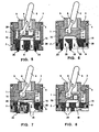
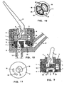
- a cartridge for a single-control mixing faucet comprises, in the exemplary embodiments shown, a cage or casing 1 that ends below with a retaining shoulder 2, a lid 3 coupled with elastic release by means of teeth 4 to openings of cage 1, a ring member 5 rotatably seated in lid 3, an operating lever 6 with an internal control member 7, pivoted by means of an axis 8 to the rotatable ring 5, an operatively fixed plate 9 and an operatively movable plate 10.
- these plates 9 and 10 which in a well-known manner are intended to work as flow control members by means of properly shaped recesses and openings, are made by means of molding a phenolic resin and subsequently lapping the flat surfaces of the plates which, when in the mounted state, are in mutual contact.
- lever 6 which can be oscillated or rotated, one can impart translation and rotation movements to the movable plate 10 with respect to the fixed plate 9 in order to control, thanks to suitable configurations in terms of recesses and openings of these plates, the flow of delivered mixed water as well as the mixing ratio between cold water and hot water.
- a cartridge of the kind shown here as an example is intended to be inserted in body 11 of a hydraulic equipment unit, which in this example is a single-control mixing faucet and, in the shape shown in Figure 12, is provided with a delivery spout 12 (while, in other cases, the delivery takes place through a pipe); body 11 of the faucet is reached by two water pipelines, respectively for cold water and hot water, only one of which, 13, is visible in Figure 12.
- Body 11 of the faucet is closed on top by a lid 14, which for example may be screwed and is intended to retain the cartridge in its operating position.
- the operatively fixed plate 9 has an upper protruding rim 15, intended to cooperate with the retaining shoulder 2, and it is mounted in casing 1 by simply inserting it in the casing prior to the introduction of the other components.
- This particularly manner of assembly which is advantageous especially for an instrumental assembly, is made possible, on the one hand, thanks to the possibility of giving the plate according to the invention certain particular configurations, such as rim 15, and, on the other hand, thanks to the reduced shape and dimension tolerances which can be obtained for the plates and which permit the effective coupling of the fixed plate 9 with casing 1 of the cartridge.
- each passing opening 18 of the fixed plate can be made up of a plurality of narrow openings separated by thin material dividers, that could be made only with great difficulty and high costs according to the prior state of the art.
- the movable plate 10 has itself a seat that cooperates with the internal control member 7 of the operating lever 6.
- the movable plate 10 can be so shaped as to receive a member 16 that presents a seat which cooperates with the internal control member 7 of the operating lever 6.
- Member 16 serves primarily to permit the employment of the same fixed plate 10 in the presence of differently shaped control members 7.
- these control members can have, for example, the shapes of flat discs, as shown, or of studs.
- member 16 can advantageously have an antifriction effect.
- the advantageous configurations described can be implemented easily, on the one hand, thanks to the possibility of giving the movable plate according to the invention certain configurations that are difficult to make in the plates according to the prior technique and, on the other hand, thanks to the reduced shape and dimension tolerances that can be obtained for the plates and that permit effective coupling of the movable plate 10 with the control member 7 of the cartridge or with member 16. This is one of the reasons why it is possible to omit a related support member in the shape of a slide for the movable plate according to the invention.
- the movable plate 10 has a recess 17 that is appropriately profiled and is intended to establish communications between the passing openings 18 of the fixed plate 9.
- These parts generally are not modified by the application of the invention, except that their shapes can be chosen by the designer with a greater degree of freedom.
- the profiled recesses 17 of the movable plate 10 can be replaced by passing openings and/or by a particular outline of the periphery of the plate 10, according to the teachings of the known state of the art.
- the fixed plate 9 can have seats that are sufficiently recessed to hold packings 19. These seats can also be very deep, as shown by Figures 5, 6 and 12, in order to retain very high packings 20, which are particularly safe against the danger of expulsion and which can also perform the function of compensating for the machining tolerances; they can have complex configuration, as shown for example in Figure 10.
- the seats for packings made in the fixed plate 9 can also take on larger dimensions in order to accommodate a dynamic packing 21 in the form of a sleeve, as shown in Figure 7, or to accommodate packings 22, equipped with internal pipes 23 for purposes of rigidification, as shown in Figure 9.
- the fixed plate 9 can have accentuated reliefs on which can be inserted or directly molded packings 24.
- These packings can extend so as to work also radially, in addition to axially, and thereby they render the employment of separate radial packings superfluous when a radial seal is necessary.
- the fixed plate 9 can furthermore have flarings 25 that may also be rather extensive, which modify the cross section of its passing openings from point to point along the thickness of the plate, in order to optimize the connection between the openings that cooperate with the movable plate and the openings for intake and outlet; a function which so far was assigned to the supporting bottom member of the fixed plate.
- the movable plate 10 as shown in Figure 7, can have in its recess 17 configurations 26 like studs or lamellae, constituting a mechanical flow noise absorber; and it can also have an extended seat in order to hold a capsule 27 for the pneumatic absorption of the flow noise, as shown in Figure 8.
- the fixed plate 9 can have one or several seats 29, intended to receive positioning studs. These seats 29 can be made in a number larger then the number really required for the positioning studs, which thus can be given differentiated positions, depending on the various practical application requirements or the different requests of the clients.
- cavities in them that may be more or less large, such as the cavities 30 shown in Figure 5.
- These cavities are used in particular to localize the action of the extractors used during molding, in regions where the traces and reliefs that they generally leave on the workpiece will not cause any disturbance.
- these cavities make it possible to keep the thicknesses of the molded piece relatively uniform, thus preventing deformations due to shrinkage, constitute containment spaces for a lubricating grease, and reduce the material consumption.
- the plates manufactured according to the invention are particularly suitable for receiving the surfacing with hard materials, especially by means of physical or chemical deposition from a gaseous medium. This is due both to the nature of the materials forming the plates, and to the possibility of mixing to the same other materials capable of favoring the deposition and of improving the adhesion of the deposited materials.
Landscapes
- Engineering & Computer Science (AREA)
- General Engineering & Computer Science (AREA)
- Mechanical Engineering (AREA)
- Multiple-Way Valves (AREA)
- Injection Moulding Of Plastics Or The Like (AREA)
- Phenolic Resins Or Amino Resins (AREA)
- Lubricants (AREA)
- Reciprocating Pumps (AREA)
- Casting Or Compression Moulding Of Plastics Or The Like (AREA)
- Casting Support Devices, Ladles, And Melt Control Thereby (AREA)
Applications Claiming Priority (3)
| Application Number | Priority Date | Filing Date | Title |
|---|---|---|---|
| ITTO20010551 | 2001-06-08 | ||
| IT2001TO000551A ITTO20010551A1 (it) | 2001-06-08 | 2001-06-08 | Organi di controllo del flusso in materiale duro per apparecchi idraulici. |
| PCT/EP2002/005839 WO2002101272A1 (en) | 2001-06-08 | 2002-05-28 | Flow control members made of thermosetting synthetic polymer for hydraulic equipment units |
Publications (2)
| Publication Number | Publication Date |
|---|---|
| EP1402209A1 EP1402209A1 (en) | 2004-03-31 |
| EP1402209B1 true EP1402209B1 (en) | 2007-05-02 |
Family
ID=11458939
Family Applications (1)
| Application Number | Title | Priority Date | Filing Date |
|---|---|---|---|
| EP02743116A Expired - Lifetime EP1402209B1 (en) | 2001-06-08 | 2002-05-28 | Flow control members made of phenolic resin for hydraulic equipment units |
Country Status (7)
| Country | Link |
|---|---|
| US (1) | US20040069358A1 (it) |
| EP (1) | EP1402209B1 (it) |
| CN (1) | CN1514918A (it) |
| AT (1) | ATE361442T1 (it) |
| DE (1) | DE60219916D1 (it) |
| IT (1) | ITTO20010551A1 (it) |
| WO (1) | WO2002101272A1 (it) |
Families Citing this family (18)
| Publication number | Priority date | Publication date | Assignee | Title |
|---|---|---|---|---|
| US7866342B2 (en) | 2002-12-18 | 2011-01-11 | Vapor Technologies, Inc. | Valve component for faucet |
| US8220489B2 (en) | 2002-12-18 | 2012-07-17 | Vapor Technologies Inc. | Faucet with wear-resistant valve component |
| US7866343B2 (en) | 2002-12-18 | 2011-01-11 | Masco Corporation Of Indiana | Faucet |
| US8555921B2 (en) | 2002-12-18 | 2013-10-15 | Vapor Technologies Inc. | Faucet component with coating |
| DE102007014251A1 (de) * | 2007-03-24 | 2008-09-25 | Hansa Metallwerke Ag | Sanitärarmatur |
| US7779865B2 (en) * | 2007-04-20 | 2010-08-24 | Kohler Co. | Plumbing valve with undulating disk surface |
| US8327882B2 (en) * | 2007-11-15 | 2012-12-11 | Xiamen Lota International Co., Ltd. | Water faucet with joystick cartridge |
| US8297305B2 (en) | 2008-01-28 | 2012-10-30 | Kohler Co. | Valve assembly having an improved flow path |
| HU230570B1 (hu) * | 2009-12-21 | 2016-12-28 | Kerox Ipari És Kereskedelmi Kft. | Egykaros keverő csaptelep betét megnövelt szögű komfort tartománnyal |
| TWI440789B (zh) * | 2010-12-24 | 2014-06-11 | Delta Electronics Inc | 滑動式閥門裝置 |
| US20150107706A1 (en) * | 2013-10-18 | 2015-04-23 | Delavan Inc. | Vortex chamber for fluid control valves |
| US9267612B2 (en) * | 2013-10-30 | 2016-02-23 | Kuching International Ltd. | Anti-pressure ceramic valve |
| CN104480717A (zh) * | 2014-10-31 | 2015-04-01 | 山东腾工轴承有限公司 | 一种自润滑关节轴承聚四氟乙烯/凯夫拉织物衬垫改性材料及改性方法 |
| EP3377792B1 (en) * | 2016-01-14 | 2023-07-19 | Phoenix Industries Pty Ltd | Adjustable flow regulator |
| CN106224593A (zh) * | 2016-08-25 | 2016-12-14 | 宁波长壁流体动力科技有限公司 | 一种换向阀 |
| US11231117B1 (en) * | 2020-09-23 | 2022-01-25 | Kuching International Ltd. | Water control valve |
| JP7750664B2 (ja) * | 2021-03-22 | 2025-10-07 | Ntn株式会社 | 弁座の製造方法 |
| JP7579103B2 (ja) * | 2020-09-30 | 2024-11-07 | Ntn株式会社 | 弁座およびディスクバルブ装置 |
Citations (1)
| Publication number | Priority date | Publication date | Assignee | Title |
|---|---|---|---|---|
| US3233732A (en) * | 1962-02-28 | 1966-02-08 | Tait Mfg Co The | Water softening system |
Family Cites Families (16)
| Publication number | Priority date | Publication date | Assignee | Title |
|---|---|---|---|---|
| US3433264A (en) | 1967-02-28 | 1969-03-18 | American Standard Inc | Noise reduction structure for mixing valve |
| US3920043A (en) * | 1974-10-09 | 1975-11-18 | American Standard Inc | Low noise faucet |
| DE3025596A1 (de) * | 1980-07-05 | 1982-02-25 | Feldmühle AG, 4000 Düsseldorf | Ventilscheibe aus oxidkeramischem werkstoff |
| IT8424101U1 (it) * | 1984-12-17 | 1986-06-17 | Rubinetterie Flii Frattini S P A | Piastrine ceramiche per cartucce di miscelatori idraulici monocomando |
| US4935313A (en) * | 1985-02-12 | 1990-06-19 | Masco Corporation Of Indiana | Process of manufacturing seal members having a low friction coefficient |
| IT1183856B (it) * | 1985-05-28 | 1987-10-22 | Gevipi Ag | Rubinetto miscelatore a piastrine in materiale duro con mezzi di prechiusura |
| FR2637132B1 (fr) | 1988-09-26 | 1990-11-02 | Air Liquide | Gaz lasants et procede de travail au laser co2 |
| US5372161A (en) * | 1989-09-02 | 1994-12-13 | Friedrich Grohe Armaturenfabrik Gmbh & Co. | Valve plates for single-control valve |
| IT1240164B (it) | 1990-04-02 | 1993-11-27 | Gevipi Ag | Cartuccia per rubinetto a piastrine in materiale duro, con mezzi di ritegno della piastrina fissa in stato di coazione. |
| US5518027A (en) * | 1992-09-30 | 1996-05-21 | Ntn Corporation | Valve assembly |
| IT1261305B (it) * | 1993-06-22 | 1996-05-14 | Gevipi Ag | Dispositivo smorzatore di vibrazioni e di rumore, per impianti idraulici |
| US5402827A (en) | 1993-09-08 | 1995-04-04 | Emhart Inc. | Single control cartridge valve |
| DE19580519B3 (de) * | 1994-03-31 | 2014-03-06 | Ntn Corp. | Ventilanordnung |
| JP3532641B2 (ja) * | 1994-11-16 | 2004-05-31 | 日本特殊陶業株式会社 | 多孔質セラミック材料とその製造方法、及びバルブユニット |
| US6019132A (en) * | 1996-10-01 | 2000-02-01 | Masco Corporation Of Indiana | Plug with anchored retaining packings for a cartridge for a water faucet |
| HU223929B1 (hu) * | 1997-04-04 | 2005-03-29 | KEROX-MULTIPOLÁR II. Kft. | Gömbpálya vezérlésű síktárcsás keverő csaptelepbetét |
-
2001
- 2001-06-08 IT IT2001TO000551A patent/ITTO20010551A1/it unknown
-
2002
- 2002-05-28 DE DE60219916T patent/DE60219916D1/de not_active Expired - Lifetime
- 2002-05-28 EP EP02743116A patent/EP1402209B1/en not_active Expired - Lifetime
- 2002-05-28 CN CNA028115147A patent/CN1514918A/zh active Pending
- 2002-05-28 US US10/466,989 patent/US20040069358A1/en not_active Abandoned
- 2002-05-28 AT AT02743116T patent/ATE361442T1/de not_active IP Right Cessation
- 2002-05-28 WO PCT/EP2002/005839 patent/WO2002101272A1/en not_active Ceased
Patent Citations (1)
| Publication number | Priority date | Publication date | Assignee | Title |
|---|---|---|---|---|
| US3233732A (en) * | 1962-02-28 | 1966-02-08 | Tait Mfg Co The | Water softening system |
Also Published As
| Publication number | Publication date |
|---|---|
| ATE361442T1 (de) | 2007-05-15 |
| EP1402209A1 (en) | 2004-03-31 |
| WO2002101272A1 (en) | 2002-12-19 |
| ITTO20010551A1 (it) | 2002-12-08 |
| US20040069358A1 (en) | 2004-04-15 |
| DE60219916D1 (de) | 2007-06-14 |
| CN1514918A (zh) | 2004-07-21 |
Similar Documents
| Publication | Publication Date | Title |
|---|---|---|
| EP1402209B1 (en) | Flow control members made of phenolic resin for hydraulic equipment units | |
| US4966789A (en) | Process of manufacturing seal members having a low friction coefficient | |
| CA2820556C (en) | Ball valve | |
| EP1543261B1 (en) | Stop valve | |
| FI80139B (fi) | Blandarventil med haordmetallbelaeggning och foersedd med en roerlig av vattentrycket belastad patron. | |
| FI91189B (fi) | Säätöpatruuna vedensekoitushanaa varten | |
| AU2016206944B2 (en) | Extreme service plug valve | |
| US5372161A (en) | Valve plates for single-control valve | |
| US9822895B2 (en) | Metal reinforced seal plate for pilot actuated spool valve | |
| AU2534788A (en) | Mixing tap with pressure responsive sealing | |
| CA1161017A (en) | Seal for wear resistant inserts | |
| US4935313A (en) | Process of manufacturing seal members having a low friction coefficient | |
| CA1155468A (en) | Secondary sealing element for mechanical seals | |
| US4983355A (en) | Seal element of hard material sintered from a semi-finished form with organic binder | |
| DE102004035658B4 (de) | Axialwellendichtung | |
| US3265351A (en) | Segmental disc stem connection for valves | |
| CA1338111C (en) | Pair of seal members of hard material having a low friction coefficient | |
| US3351351A (en) | Means for sealing a spindle | |
| CN219755402U (zh) | 一种全金属硬密封v型球阀 | |
| US3353784A (en) | Valve construction | |
| JP3447390B2 (ja) | 摺動装置 | |
| PL185225B1 (pl) | Zawór kurkowy z czopem kulistym | |
| CN109340396A (zh) | 一种防腐蚀衬氟球阀及其阀体制造工艺 | |
| JPS601475A (ja) | バタフライ弁 | |
| KR200358254Y1 (ko) | 주조접합시트를 갖는 버터플라이밸브용 밸브디스크 |
Legal Events
| Date | Code | Title | Description |
|---|---|---|---|
| PUAI | Public reference made under article 153(3) epc to a published international application that has entered the european phase |
Free format text: ORIGINAL CODE: 0009012 |
|
| 17P | Request for examination filed |
Effective date: 20031223 |
|
| AK | Designated contracting states |
Kind code of ref document: A1 Designated state(s): AT BE CH CY DE DK ES FI FR GB GR IE IT LI LU MC NL PT SE TR |
|
| AX | Request for extension of the european patent |
Extension state: AL LT LV MK RO SI |
|
| 17Q | First examination report despatched |
Effective date: 20050125 |
|
| GRAP | Despatch of communication of intention to grant a patent |
Free format text: ORIGINAL CODE: EPIDOSNIGR1 |
|
| RTI1 | Title (correction) |
Free format text: FLOW CONTROL MEMBERS MADE OF PHENOLIC RESIN FOR HYDRAULIC EQUIPMENT UNITS |
|
| GRAS | Grant fee paid |
Free format text: ORIGINAL CODE: EPIDOSNIGR3 |
|
| GRAA | (expected) grant |
Free format text: ORIGINAL CODE: 0009210 |
|
| AK | Designated contracting states |
Kind code of ref document: B1 Designated state(s): AT BE CH CY DE DK ES FI FR GB GR IE IT LI LU MC NL PT SE TR |
|
| PG25 | Lapsed in a contracting state [announced via postgrant information from national office to epo] |
Ref country code: FI Free format text: LAPSE BECAUSE OF FAILURE TO SUBMIT A TRANSLATION OF THE DESCRIPTION OR TO PAY THE FEE WITHIN THE PRESCRIBED TIME-LIMIT Effective date: 20070502 Ref country code: CH Free format text: LAPSE BECAUSE OF FAILURE TO SUBMIT A TRANSLATION OF THE DESCRIPTION OR TO PAY THE FEE WITHIN THE PRESCRIBED TIME-LIMIT Effective date: 20070502 Ref country code: LI Free format text: LAPSE BECAUSE OF FAILURE TO SUBMIT A TRANSLATION OF THE DESCRIPTION OR TO PAY THE FEE WITHIN THE PRESCRIBED TIME-LIMIT Effective date: 20070502 |
|
| REG | Reference to a national code |
Ref country code: GB Ref legal event code: FG4D |
|
| REG | Reference to a national code |
Ref country code: CH Ref legal event code: EP |
|
| REG | Reference to a national code |
Ref country code: IE Ref legal event code: FG4D |
|
| REF | Corresponds to: |
Ref document number: 60219916 Country of ref document: DE Date of ref document: 20070614 Kind code of ref document: P |
|
| PG25 | Lapsed in a contracting state [announced via postgrant information from national office to epo] |
Ref country code: SE Free format text: LAPSE BECAUSE OF FAILURE TO SUBMIT A TRANSLATION OF THE DESCRIPTION OR TO PAY THE FEE WITHIN THE PRESCRIBED TIME-LIMIT Effective date: 20070802 |
|
| PG25 | Lapsed in a contracting state [announced via postgrant information from national office to epo] |
Ref country code: ES Free format text: LAPSE BECAUSE OF FAILURE TO SUBMIT A TRANSLATION OF THE DESCRIPTION OR TO PAY THE FEE WITHIN THE PRESCRIBED TIME-LIMIT Effective date: 20070813 |
|
| NLV1 | Nl: lapsed or annulled due to failure to fulfill the requirements of art. 29p and 29m of the patents act | ||
| REG | Reference to a national code |
Ref country code: CH Ref legal event code: PL |
|
| PG25 | Lapsed in a contracting state [announced via postgrant information from national office to epo] |
Ref country code: AT Free format text: LAPSE BECAUSE OF FAILURE TO SUBMIT A TRANSLATION OF THE DESCRIPTION OR TO PAY THE FEE WITHIN THE PRESCRIBED TIME-LIMIT Effective date: 20070502 |
|
| EN | Fr: translation not filed | ||
| PG25 | Lapsed in a contracting state [announced via postgrant information from national office to epo] |
Ref country code: BE Free format text: LAPSE BECAUSE OF FAILURE TO SUBMIT A TRANSLATION OF THE DESCRIPTION OR TO PAY THE FEE WITHIN THE PRESCRIBED TIME-LIMIT Effective date: 20070502 |
|
| PG25 | Lapsed in a contracting state [announced via postgrant information from national office to epo] |
Ref country code: PT Free format text: LAPSE BECAUSE OF FAILURE TO SUBMIT A TRANSLATION OF THE DESCRIPTION OR TO PAY THE FEE WITHIN THE PRESCRIBED TIME-LIMIT Effective date: 20071002 Ref country code: NL Free format text: LAPSE BECAUSE OF FAILURE TO SUBMIT A TRANSLATION OF THE DESCRIPTION OR TO PAY THE FEE WITHIN THE PRESCRIBED TIME-LIMIT Effective date: 20070502 Ref country code: MC Free format text: LAPSE BECAUSE OF NON-PAYMENT OF DUE FEES Effective date: 20070531 Ref country code: DK Free format text: LAPSE BECAUSE OF FAILURE TO SUBMIT A TRANSLATION OF THE DESCRIPTION OR TO PAY THE FEE WITHIN THE PRESCRIBED TIME-LIMIT Effective date: 20070502 Ref country code: DE Free format text: LAPSE BECAUSE OF FAILURE TO SUBMIT A TRANSLATION OF THE DESCRIPTION OR TO PAY THE FEE WITHIN THE PRESCRIBED TIME-LIMIT Effective date: 20070803 |
|
| PLBE | No opposition filed within time limit |
Free format text: ORIGINAL CODE: 0009261 |
|
| STAA | Information on the status of an ep patent application or granted ep patent |
Free format text: STATUS: NO OPPOSITION FILED WITHIN TIME LIMIT |
|
| 26N | No opposition filed |
Effective date: 20080205 |
|
| PG25 | Lapsed in a contracting state [announced via postgrant information from national office to epo] |
Ref country code: GR Free format text: LAPSE BECAUSE OF FAILURE TO SUBMIT A TRANSLATION OF THE DESCRIPTION OR TO PAY THE FEE WITHIN THE PRESCRIBED TIME-LIMIT Effective date: 20070803 Ref country code: FR Free format text: LAPSE BECAUSE OF FAILURE TO SUBMIT A TRANSLATION OF THE DESCRIPTION OR TO PAY THE FEE WITHIN THE PRESCRIBED TIME-LIMIT Effective date: 20071228 Ref country code: IT Free format text: LAPSE BECAUSE OF FAILURE TO SUBMIT A TRANSLATION OF THE DESCRIPTION OR TO PAY THE FEE WITHIN THE PRESCRIBED TIME-LIMIT Effective date: 20070502 |
|
| PG25 | Lapsed in a contracting state [announced via postgrant information from national office to epo] |
Ref country code: IE Free format text: LAPSE BECAUSE OF NON-PAYMENT OF DUE FEES Effective date: 20070528 |
|
| PG25 | Lapsed in a contracting state [announced via postgrant information from national office to epo] |
Ref country code: FR Free format text: LAPSE BECAUSE OF FAILURE TO SUBMIT A TRANSLATION OF THE DESCRIPTION OR TO PAY THE FEE WITHIN THE PRESCRIBED TIME-LIMIT Effective date: 20070502 |
|
| PG25 | Lapsed in a contracting state [announced via postgrant information from national office to epo] |
Ref country code: CY Free format text: LAPSE BECAUSE OF FAILURE TO SUBMIT A TRANSLATION OF THE DESCRIPTION OR TO PAY THE FEE WITHIN THE PRESCRIBED TIME-LIMIT Effective date: 20070502 |
|
| PG25 | Lapsed in a contracting state [announced via postgrant information from national office to epo] |
Ref country code: LU Free format text: LAPSE BECAUSE OF NON-PAYMENT OF DUE FEES Effective date: 20070528 |
|
| PG25 | Lapsed in a contracting state [announced via postgrant information from national office to epo] |
Ref country code: TR Free format text: LAPSE BECAUSE OF FAILURE TO SUBMIT A TRANSLATION OF THE DESCRIPTION OR TO PAY THE FEE WITHIN THE PRESCRIBED TIME-LIMIT Effective date: 20070502 |
|
| PGFP | Annual fee paid to national office [announced via postgrant information from national office to epo] |
Ref country code: GB Payment date: 20120426 Year of fee payment: 11 |
|
| GBPC | Gb: european patent ceased through non-payment of renewal fee |
Effective date: 20130528 |
|
| PG25 | Lapsed in a contracting state [announced via postgrant information from national office to epo] |
Ref country code: GB Free format text: LAPSE BECAUSE OF NON-PAYMENT OF DUE FEES Effective date: 20130528 |