EP1402952A1 - Cartouche avec moyen d' entrainement et système de manipulation - Google Patents
Cartouche avec moyen d' entrainement et système de manipulation Download PDFInfo
- Publication number
- EP1402952A1 EP1402952A1 EP03020881A EP03020881A EP1402952A1 EP 1402952 A1 EP1402952 A1 EP 1402952A1 EP 03020881 A EP03020881 A EP 03020881A EP 03020881 A EP03020881 A EP 03020881A EP 1402952 A1 EP1402952 A1 EP 1402952A1
- Authority
- EP
- European Patent Office
- Prior art keywords
- piston
- cartridge
- tank
- drive
- liquid
- Prior art date
- Legal status (The legal status is an assumption and is not a legal conclusion. Google has not performed a legal analysis and makes no representation as to the accuracy of the status listed.)
- Granted
Links
- 239000007788 liquid Substances 0.000 claims description 41
- 239000000126 substance Substances 0.000 claims description 20
- 238000005086 pumping Methods 0.000 claims description 6
- 238000007599 discharging Methods 0.000 claims 1
- 238000004458 analytical method Methods 0.000 abstract description 14
- 239000012530 fluid Substances 0.000 abstract 4
- 238000003745 diagnosis Methods 0.000 abstract 2
- 238000004519 manufacturing process Methods 0.000 description 13
- 238000000034 method Methods 0.000 description 12
- 239000007789 gas Substances 0.000 description 10
- 230000008569 process Effects 0.000 description 9
- 238000004140 cleaning Methods 0.000 description 6
- 239000013013 elastic material Substances 0.000 description 6
- 238000001514 detection method Methods 0.000 description 4
- 238000011156 evaluation Methods 0.000 description 4
- 235000013305 food Nutrition 0.000 description 4
- 239000002184 metal Substances 0.000 description 4
- 230000008901 benefit Effects 0.000 description 3
- 210000004369 blood Anatomy 0.000 description 3
- 239000008280 blood Substances 0.000 description 3
- 108091028043 Nucleic acid sequence Proteins 0.000 description 2
- 230000003749 cleanliness Effects 0.000 description 2
- 230000008878 coupling Effects 0.000 description 2
- 238000010168 coupling process Methods 0.000 description 2
- 238000005859 coupling reaction Methods 0.000 description 2
- 230000007613 environmental effect Effects 0.000 description 2
- 239000004744 fabric Substances 0.000 description 2
- 230000002068 genetic effect Effects 0.000 description 2
- 238000011835 investigation Methods 0.000 description 2
- 239000000463 material Substances 0.000 description 2
- 230000007246 mechanism Effects 0.000 description 2
- 238000007789 sealing Methods 0.000 description 2
- 239000011343 solid material Substances 0.000 description 2
- 108020004414 DNA Proteins 0.000 description 1
- 240000000731 Fagus sylvatica Species 0.000 description 1
- 235000010099 Fagus sylvatica Nutrition 0.000 description 1
- 241000700605 Viruses Species 0.000 description 1
- 230000009471 action Effects 0.000 description 1
- 239000003570 air Substances 0.000 description 1
- 239000012080 ambient air Substances 0.000 description 1
- 230000001580 bacterial effect Effects 0.000 description 1
- 244000052616 bacterial pathogen Species 0.000 description 1
- 238000012742 biochemical analysis Methods 0.000 description 1
- 230000015572 biosynthetic process Effects 0.000 description 1
- 229910052729 chemical element Inorganic materials 0.000 description 1
- 150000001875 compounds Chemical class 0.000 description 1
- 239000000356 contaminant Substances 0.000 description 1
- 238000001816 cooling Methods 0.000 description 1
- 238000013461 design Methods 0.000 description 1
- 238000011161 development Methods 0.000 description 1
- 230000018109 developmental process Effects 0.000 description 1
- 239000003814 drug Substances 0.000 description 1
- 238000000835 electrochemical detection Methods 0.000 description 1
- 230000003203 everyday effect Effects 0.000 description 1
- 239000012634 fragment Substances 0.000 description 1
- 210000004051 gastric juice Anatomy 0.000 description 1
- 238000010438 heat treatment Methods 0.000 description 1
- 230000010354 integration Effects 0.000 description 1
- 238000001990 intravenous administration Methods 0.000 description 1
- 229940127554 medical product Drugs 0.000 description 1
- 230000002906 microbiologic effect Effects 0.000 description 1
- 238000012543 microbiological analysis Methods 0.000 description 1
- 230000000704 physical effect Effects 0.000 description 1
- 230000002028 premature Effects 0.000 description 1
- 230000029058 respiratory gaseous exchange Effects 0.000 description 1
- 210000003296 saliva Anatomy 0.000 description 1
- 238000005507 spraying Methods 0.000 description 1
- 238000003860 storage Methods 0.000 description 1
- 239000000725 suspension Substances 0.000 description 1
- 238000012360 testing method Methods 0.000 description 1
- 238000012546 transfer Methods 0.000 description 1
- 210000002700 urine Anatomy 0.000 description 1
- XLYOFNOQVPJJNP-UHFFFAOYSA-N water Substances O XLYOFNOQVPJJNP-UHFFFAOYSA-N 0.000 description 1
Images

Classifications
-
- G—PHYSICS
- G01—MEASURING; TESTING
- G01N—INVESTIGATING OR ANALYSING MATERIALS BY DETERMINING THEIR CHEMICAL OR PHYSICAL PROPERTIES
- G01N1/00—Sampling; Preparing specimens for investigation
- G01N1/02—Devices for withdrawing samples
- G01N1/10—Devices for withdrawing samples in the liquid or fluent state
- G01N1/14—Suction devices, e.g. pumps; Ejector devices
-
- B—PERFORMING OPERATIONS; TRANSPORTING
- B01—PHYSICAL OR CHEMICAL PROCESSES OR APPARATUS IN GENERAL
- B01L—CHEMICAL OR PHYSICAL LABORATORY APPARATUS FOR GENERAL USE
- B01L3/00—Containers or dishes for laboratory use, e.g. laboratory glassware; Droppers
- B01L3/02—Burettes; Pipettes
- B01L3/021—Pipettes, i.e. with only one conduit for withdrawing and redistributing liquids
- B01L3/0217—Pipettes, i.e. with only one conduit for withdrawing and redistributing liquids of the plunger pump type
-
- B—PERFORMING OPERATIONS; TRANSPORTING
- B01—PHYSICAL OR CHEMICAL PROCESSES OR APPARATUS IN GENERAL
- B01L—CHEMICAL OR PHYSICAL LABORATORY APPARATUS FOR GENERAL USE
- B01L2200/00—Solutions for specific problems relating to chemical or physical laboratory apparatus
- B01L2200/02—Adapting objects or devices to another
-
- B—PERFORMING OPERATIONS; TRANSPORTING
- B01—PHYSICAL OR CHEMICAL PROCESSES OR APPARATUS IN GENERAL
- B01L—CHEMICAL OR PHYSICAL LABORATORY APPARATUS FOR GENERAL USE
- B01L2200/00—Solutions for specific problems relating to chemical or physical laboratory apparatus
- B01L2200/04—Exchange or ejection of cartridges, containers or reservoirs
-
- B—PERFORMING OPERATIONS; TRANSPORTING
- B01—PHYSICAL OR CHEMICAL PROCESSES OR APPARATUS IN GENERAL
- B01L—CHEMICAL OR PHYSICAL LABORATORY APPARATUS FOR GENERAL USE
- B01L2200/00—Solutions for specific problems relating to chemical or physical laboratory apparatus
- B01L2200/14—Process control and prevention of errors
- B01L2200/141—Preventing contamination, tampering
-
- B—PERFORMING OPERATIONS; TRANSPORTING
- B01—PHYSICAL OR CHEMICAL PROCESSES OR APPARATUS IN GENERAL
- B01L—CHEMICAL OR PHYSICAL LABORATORY APPARATUS FOR GENERAL USE
- B01L2200/00—Solutions for specific problems relating to chemical or physical laboratory apparatus
- B01L2200/16—Reagents, handling or storing thereof
Definitions
- the invention relates to a cartridge for handling and transporting a liquid or gaseous substance and a system for handling a liquid or gaseous substance using such a cartridge.
- the invention relates in particular to a cartridge for handling a liquid or gaseous substance to be examined medically, and to an analysis device for examining medically relevant properties of a liquid or gaseous substance using such a cartridge.
- the detection of nucleotide sequences is normally based on a two-stage procedure, in the first stage of which DNA fragments present in the liquid are reproduced many times in order to increase the probability of detection for the actual detection in the second stage of the detection procedure. Since genetic contaminants are also multiplied, these processes place particularly high demands on the cleanliness of the process equipment.
- the object of the invention is to enable the handling of liquid or gaseous substances in cartridges which, on the one hand, require only a small amount of handling, but on the other hand are inexpensive to manufacture, so that they can also be used economically as disposable products.
- the invention solves this problem by a device according to the features of claim 1 or by a system according to the features of the further independent claims.
- the invention is based on the idea of using a cartridge for handling liquids and gases which has an integral pump system to be driven from outside the cartridge.
- a cartridge should be understood to mean a fabric container that is adapted to the respective requirements, which can be thick or thin-walled and additional Features such as integrated heating or cooling systems or otherwise.
- the pump system which can be understood as a pump piston, for example, can be automatically coupled and uncoupled to the pump drive of a handling system by means of a positive connection. It is therefore not necessary to use additional pump systems such as syringes or piston pumps for handling. As a result, additional effort for coupling and decoupling the cartridge to a handling system can be avoided in handling.
- the invention is further based on the idea that, in addition to the cartridge, the pump system is also based on inexpensive components such as plastic molded parts.
- the cartridge can be manufactured inexpensively and made available in large numbers.
- the economic producibility of large quantities is of particular advantage when using the cartridge for central, standard laboratory testing of large numbers of samples that have to be taken on site in a spatially distributed manner.
- the inexpensive manufacture of the cartridge in large quantities also makes it economically usable as a single-use product. On the one hand, this can reduce the logistical effort with frequent, spatially distributed use.
- the complex cleaning of the cartridges can be omitted.
- cartridges that are not yet contaminated during production are sterilized or cleaned, depending on requirements, and finally sealed, e.g. in a blister, as is usual for medical products.
- the much more complex cleaning of cartridges that are already used, i.e. contaminated, is then completely unnecessary.
- the production outlay is minimized in that the automatically producible connection between the integral pump system of the cartridge and the pump drive of the analysis or dosing device is dispensed with, without complex, mechanically working parts and only on the basis of an elastic molded part.
- the elastic molded part is designed in such a way that it has latching or jaw elements which, when the integral pump system is advanced by the external pump drive, forms a positive connection with the latter in relation to longitudinal movements.
- the positive connection is designed so that the integral pump system can also be pulled back by the external pump drive, the positive connection being released when the integral pump system has returned to its starting position when it is pulled back.
- the integrated pump system is also designed as a one-way system. If necessary, it can be subjected to the same cleaning steps as the entire cartridge and therefore meets the same purity requirements. When used one way, it also does not have to be laboriously cleaned for reuse.
- the purity of the liquids or gases to be handled also benefits from the integration of the pump system, that the transfer via and contact with additional pump systems, e.g. Spraying, is avoided.
- Another basic idea of the invention is to provide a system that enables the handling of liquid or gaseous substances by means of an inexpensive cartridge that can be automatically coupled and decoupled with the system by means of a positive connection.
- the number of individual handling steps can be reduced by the automatic coupling.
- the inexpensive manufacturability of the cartridge enables economical use in large quantities and as a single-use product.
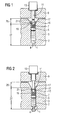
- FIG. 1 shows a system according to the invention with a cartridge 3 and a metering or analysis device 9 .
- the cartridge 3 can be made of plastic, metal or another suitable material.
- the cartridge 3 has a tank 2 shaped as a cylinder, the cross section of which can in principle be of any shape, but which is preferably circular for the sake of simpler manufacture.
- a liquid 1 in FIG. 1 which is pumped in via an opening 4 located on the front side of the tank 2 .
- a piston 5 is arranged in the tank 2 and can be pushed back and forth in order to pump the liquid 1 in or out.
- the surfaces on both sides have a corresponding surface quality.
- at least one of the two sealing partners can be made of elastic material, for example piston 5 can be made of elastic plastic.
- sealing rings can also be arranged on the piston 5 , but this is not shown in FIG. 1 .
- the piston 5 has a connecting element 7 , which is shown in FIG. 1 as a separate component mechanically connected to the piston 5 .
- a connecting element 7 which is shown in FIG. 1 as a separate component mechanically connected to the piston 5 .
- the piston 5 and the connecting element 7 integrally, ie as a single component, which can serve to reduce the manufacturing outlay.
- this may prohibit if the passing to the piston 5 in contact liquid is 1 demands on the material of the piston 5, which of the connecting member 7 are not compatible with the mechanical requirements.
- the connecting element 7 could be made of elastic plastic, but the liquid 1 has aggressive properties with regard to plastic.
- the piston 5 should not be made of plastic, but would have to be made of metal, for example.
- the piston 5 can be detected by the metering or analysis pump device 9 by means of a piston rod 11 which is driven by a drive 13 . If the piston rod 11 is advanced by the drive 13 , it can push the piston 5 deeper into the tank 2 via the connecting element 7 . As a result, liquid 1 is pumped out through the opening 4 .
- the metering or analysis pump device 9 controls the drive 13 and can thus meter the amount of liquid 1 that exits through opening 4 exactly. Due to the linear advance of the piston rod 11 and the constant cross-section of the tank 2 , the volume emerging in this case depends directly on the advance of the piston rod, with the elasticity of the piston 5 or the connecting element 7 possibly having to be taken into account.
- the invention also makes it possible to withdraw the piston 5 by pulling back the piston rod 11 and thereby pumping liquid 1 into the tank 2 through opening 4 .
- the opening 4 can either be designed as a nozzle for receiving liquid 1 , be in direct contact with the liquid 1 to be pumped in, or it a nozzle or needle can be placed on the opening 4 . If the opening 4 is not in direct contact with liquid and the piston 5 is withdrawn, ambient air is pumped into the tank 2 instead of liquid 1 .
- the connecting element 7 and the end of the piston rod 11 are designed such that a positive connection with respect to mutual longitudinal movements can be established between them.
- the connecting element 7 has a connecting bush 19 which is formed by a recess in the end of the connecting element 7 opposite the piston 5 .
- the wall of the connection element 7 has in the region of this recess latching elements 21 which are embodied in Figure 1 as semicircular jaws.
- the piston rod 11, on the other hand, has a connecting stamp 15 at its end facing the connecting element 7 , which is closed by a taper 17 .
- the connecting bush 19 and the connecting punch 15 are shaped in such a way that they can engage and engage with one another when the piston rod 11 is advanced in order to close the connection automatically.
- the cross section of the tank 2 widens towards the end in the section in which the connecting element 7 is located in FIG. 1 . This widening enables the latching elements 21 to deflect away from the connecting stamp 15 due to the elasticity of the connecting element 7 . Therefore, in Figure 1, the connection between piston rod 11 and piston 5 is not closed.
- Cartridge 3 and piston 5 as well as connecting element 7 have a relatively simple structure, which makes production and assembly as a disposable product possible in an economical manner.
- FIG. 2 shows the same system as in the previous FIG. 1 , but here with the connection between the piston 5 and the piston rod 11 closed .
- the piston rod 11 has been advanced far enough by the drive 13 to engage in the connecting bush 19 of the connecting element 7 .
- the piston 5 was advanced so far over the connecting element 7 that the latching elements 21 in FIG. 2 no longer lie in the widened section of the tank 2 , but are advanced into the cylindrical part.
- the locking elements 21 are pushed forward through the tapering section of the tank 2 , they are increasingly pressed in the direction of the connecting plunger 15 until they are fully pressed in the cylindrical section of the tank 2 .
- the locking elements 21 are pressed into the taper 17 of the piston rod 11 and the connecting stamp 15 completely fills the connecting bush 19 .
- the depth of the connecting socket 19 and the arrangement of the locking elements 21 in the socket exactly corresponds to the length of the connecting stamp 15 and the mirror-inverted arrangement of the taper 17.
- the form-fitting connection between the connecting stamp 15 and the connecting bush 19 is produced automatically by the special shape of the tank 2 .
- the connecting element 7 must be made of an elastic material in such a way that the latching elements 21 tend outward from the connecting stamp 15 without the action of an external force. Through this elastic force, they take the position shown in Figure 1 , in which the positive connection is not manufactured, automatically. As a result, when the piston rod 11 is pulled back, the connection to the connecting element 7 is released again automatically as soon as the latching elements 21 reach the expanding section from the cylindrical section of the tank 2 .
- the positive connection is thus automatically closable and automatically releasable, and is only subject to the control of the piston rod 11 by the metering or evaluation pump device 9 .
- the automatic establishment of the connection between the piston rod 11 and the piston 5 makes it possible, in particular, to connect the cartridge 3 to the metering or evaluation pump device 9 in an uncomplicated manner. It can be easily installed with just a few untrained hand movements, since the actual functional connection for controlling the pumping process is established automatically. It is therefore not subject to the precision with which the cartridge 3 is manually attached to the metering or evaluation pump device 9 . On the one hand, this increases the precision in the metering of small amounts of liquid 1 by means of the metering or evaluation pump device 9 and, on the other hand, enables the cartridge 3 to be installed and uninstalled with little effort, in particular in the case of frequent handling of large quantities.
- the system described is thus able to carry out central, in particular stationary analyzes using large quantities of disposable cartridges.
- the cartridges 3 can be manufactured as disposable cartridges in the desired degree of purity, in order to enable them to be used in analyzes critical to purity, such as are carried out in microbiology, chemistry or medicine. Large numbers of discrete quantities of substance are also possible in food production, the chemical industry or other industrial applications.
- the connecting element 7 and the connecting stamp 15 are shown enlarged in another embodiment.
- the problem can arise that the piston 5 cannot be retracted sufficiently by the piston rod 11 .
- the latching elements 21 yield elastically when the connecting plunger 15 is withdrawn and are drawn into the length.
- the latching elements are pulled into a more widened section of the tank 2 when the connecting punch 15 is withdrawn, then released, but then shorten elastically and move back into a more tapered section.
- the locking elements 21 in FIG. 3 have a shape which is less easily deformable elastically in the retraction direction than in the feed direction. Ideally, they are not elastic at all in the retraction direction but remain rigid in their position. As a result, the connection punch 15 can be pushed into the connection socket 19 more easily than can be pulled out.
- the locking elements 21 are shown as sawtooth-like serrations which, as it were, cling to the taper 7 when the piston rod 11 is pulled back, while they can be easily pushed aside via their flat side when the piston rod 11 is advanced .
- the connecting stamp 15 has a flat back on which the latching elements 21 rest without to slide sideways. In this respect, taper 7 or connecting stamp 15 and locking elements 21 play together like a tooth locking.
- FIG. 4 shows a further variant of the connecting element 7 in an enlarged view.
- the variant shown in FIG. 4 pursues the same goal as the variant shown in FIG. 3 , namely to prevent the premature loosening of the connection between the connecting punch 15 and the connecting element 7 in the retracting direction.
- mechanical latches 23 are additionally provided here. These are fastened in such a way that they can be folded aside in the direction of advance of the piston rod 11 , but are prevented from folding away in the opposite direction by stops. As a result, the connecting plunger 15 can push the catches 23 to the side when it is fed into the connecting bushing 19 without a pushing force being exerted on the piston 5 .
- the catches 23 are attached in such a way that they engage in the taper 7 as soon as the connecting punch 15 has been pushed completely into the connecting bush 19 .
- the catches 23 have to be pushed back into their starting position shown in FIG. 4 by spring force or an elastic suspension.
- the catches 23 ensure a secure, form-fitting connection between the connecting element 7 and the piston rod 11 , which cannot be released early when withdrawn, since the catches 23 cannot fold away in the retracting direction. They are not made of elastic material, but based on solid materials, such as hard plastic or metal. In contrast, the connecting element 7 is made of elastic material in order to be able to elastically drive the latching elements 21 back into their starting position, or has a correspondingly pre-tensioned spring mechanism, which is not shown in the figure.
- the connecting element 7 this is not made of elastic material, but also of a solid material such as hard plastic or metal.
- the automatic establishment of the connection between piston 5 and piston rod 11 must be ensured by an expanded functionality of the catches 23 .
- the connecting element 7 like the piston 5, is cylindrical, ie with a diameter that is constant over its length.
- the catches 23 In order to ensure the required functionality of the catches 23 , in the variant not shown, they have a bolt which blocks their movement in the direction in which they released the connecting stamp 15 . In the other direction, their movement is not restricted, so that the connection stamp 15 can be inserted into the connection socket 19 at any time without hindrance.
- the bolt that blocks the movement of the catches 23 can be designed, for example, as a toothed catch, which is released when the connecting element 7 is withdrawn in a specific longitudinal section of the tank 2 , in that an unlocking pin on the inner wall of the tank 2 releases the toothed catch.
- the cartridge 3 and the metering and analysis pump device 9 can be designed in accordance with their own requirements.
- the pump device 9 can also be a hand-controlled device that is used, for example, to take blood samples directly into the cartridge 3 as part of medical examinations.
- the drive 13 would then be a suitable manual drive and the opening 4 would be provided with a sterile intravenous needle.
- blood samples for example, water samples are to be taken for environmental or chemical investigations, such an apparatus could be used, which would then have a nozzle instead of a needle at the opening 4 of the cartridge.
- the connection between cartridge 3 and pump device 9, which can be made automatically and released again, could be used to fill or empty a large number of cartridges 3 in rapid succession by the pump device 9 .
- the cartridges 3 can be mechanically stable, dampened against vibrations, can be cooled, heated, can be easily transported due to their shape, or can be integrated into a large-scale system.
- the opening 4 can be closed and the piston 5 can be sealed in order to prevent inadvertent escape of liquid 1 .
Landscapes
- Health & Medical Sciences (AREA)
- Life Sciences & Earth Sciences (AREA)
- Chemical & Material Sciences (AREA)
- General Physics & Mathematics (AREA)
- Pathology (AREA)
- Analytical Chemistry (AREA)
- Biochemistry (AREA)
- General Health & Medical Sciences (AREA)
- Hydrology & Water Resources (AREA)
- Immunology (AREA)
- Physics & Mathematics (AREA)
- Clinical Laboratory Science (AREA)
- Chemical Kinetics & Catalysis (AREA)
- Infusion, Injection, And Reservoir Apparatuses (AREA)
- Feeding And Controlling Fuel (AREA)
- Non-Disconnectible Joints And Screw-Threaded Joints (AREA)
- Feeding, Discharge, Calcimining, Fusing, And Gas-Generation Devices (AREA)
Applications Claiming Priority (2)
| Application Number | Priority Date | Filing Date | Title |
|---|---|---|---|
| DE10244960A DE10244960B4 (de) | 2002-09-26 | 2002-09-26 | Kartusche mit Verbindung für einen Pump-Antrieb und Handhabungs-System für einen flüssigen oder gasförmigen Stoff |
| DE10244960 | 2002-09-26 |
Publications (2)
| Publication Number | Publication Date |
|---|---|
| EP1402952A1 true EP1402952A1 (fr) | 2004-03-31 |
| EP1402952B1 EP1402952B1 (fr) | 2008-01-23 |
Family
ID=31969622
Family Applications (1)
| Application Number | Title | Priority Date | Filing Date |
|---|---|---|---|
| EP03020881A Expired - Lifetime EP1402952B1 (fr) | 2002-09-26 | 2003-09-15 | Cartouche avec moyen d' entrainement et système de manipulation |
Country Status (4)
| Country | Link |
|---|---|
| US (1) | US7182228B2 (fr) |
| EP (1) | EP1402952B1 (fr) |
| AT (1) | ATE384580T1 (fr) |
| DE (2) | DE10244960B4 (fr) |
Cited By (3)
| Publication number | Priority date | Publication date | Assignee | Title |
|---|---|---|---|---|
| EP1946831A1 (fr) * | 2006-12-12 | 2008-07-23 | Konica Minolta Medical & Graphic, Inc. | Appareil d'inspection de micro-puce modulaire |
| EP2030687A1 (fr) * | 2007-08-13 | 2009-03-04 | Hamilton Bonaduz AG | Dispositif de fermeture doté d'un mécanisme à déclic |
| IT201900006584A1 (it) * | 2019-05-07 | 2020-11-07 | Tecnorama Srl | Apparecchiatura per il prelievo e l’erogazione controllata di liquidi con dosaggio volumetrico. |
Families Citing this family (4)
| Publication number | Priority date | Publication date | Assignee | Title |
|---|---|---|---|---|
| WO2006051539A2 (fr) * | 2004-11-12 | 2006-05-18 | Shaul Ozeri | Pompe de perfusion miniature pour l'administration regulee de medicament |
| DE102010000690A1 (de) | 2010-01-05 | 2011-07-07 | Hamilton Bonaduz Ag | Dosiervorrichtung und Dosierverfahren |
| KR20130029128A (ko) * | 2010-07-23 | 2013-03-21 | 베크만 컬터, 인코포레이티드 | 실시간 pcr용 용기 |
| GB2504333B (en) * | 2012-07-26 | 2016-10-05 | Ttp Labtech Ltd | Liquid dispensing device |
Citations (3)
| Publication number | Priority date | Publication date | Assignee | Title |
|---|---|---|---|---|
| DD299156A5 (de) * | 1989-08-25 | 1992-04-02 | Microdose Pharma S.A.,Fr | Vorrichtung zur abgabe von mehrfachen kontrollierten dosen |
| EP0600580A2 (fr) * | 1992-11-18 | 1994-06-08 | Ultradent Products, Inc. | Seringue d'application avec extrémité de mixtion et de distribution détachable |
| DE19652272A1 (de) * | 1996-12-16 | 1998-08-06 | Alfred Von Schuckmann | Kartusche für Ejektoreinrichtung |
Family Cites Families (25)
| Publication number | Priority date | Publication date | Assignee | Title |
|---|---|---|---|---|
| DE299156C (fr) | ||||
| DE239540C (fr) | ||||
| DE239539C (fr) | ||||
| US2702547A (en) * | 1950-02-27 | 1955-02-22 | Antonina S Glass | Motor-driven medical injection apparatus and cartridges therefor |
| US3253592A (en) * | 1962-06-08 | 1966-05-31 | Baxter Don Inc | Plastic syringe |
| US3291128A (en) * | 1964-01-24 | 1966-12-13 | John G O'neil | Hypodermic syringe construction with sealable vent means |
| US3323682A (en) * | 1965-10-06 | 1967-06-06 | Chem Dev Corp | Disposable cartridge for gun-type dispensers |
| US3967759A (en) * | 1971-11-11 | 1976-07-06 | Mpl, Inc. | Syringe assembly with contained pop-out elastic plug seal |
| US3986645A (en) * | 1972-12-01 | 1976-10-19 | Mpl, Inc. | Liquid dispenser |
| DE2533256C3 (de) * | 1974-11-29 | 1978-04-20 | Walter Sarstedt Kunststoff-Spritzgusswerk, 5223 Nuembrecht | Blutentnahmevorrichtung |
| DE2549477C3 (de) | 1975-11-05 | 1982-01-07 | Eppendorf Gerätebau Netheler + Hinz GmbH, 2000 Hamburg | Pipettiervorrichtung |
| US4185628A (en) * | 1978-05-31 | 1980-01-29 | Kopfer Rudolph J | Compartmental syringe |
| US4465472A (en) * | 1982-11-22 | 1984-08-14 | American Hospital Supply Corp. | Syringe cartridge and method |
| US4567780A (en) * | 1984-03-12 | 1986-02-04 | American Hospital Supply Corporation | Hand-held pipette with disposable capillary |
| EP0181957A1 (fr) * | 1984-11-20 | 1986-05-28 | HTL High-Tech Lab Herstellung und Vertrieb medizinisch technischer Erzeugnisse GmbH | Pipette à dose réglable |
| DD239540A1 (de) * | 1985-07-12 | 1986-10-01 | Univ Schiller Jena | Hohlkolbenpipette |
| DD239539A1 (de) * | 1985-07-19 | 1986-10-01 | Univ Schiller Jena | Hohlkolbenpipette |
| CH671526A5 (fr) * | 1985-12-17 | 1989-09-15 | Hamilton Bonaduz Ag | |
| DE3708704A1 (de) * | 1987-03-18 | 1988-09-29 | Fischbach A Kunststoff Kg | Kartusche fuer pastoese massen |
| US4890627A (en) * | 1987-11-09 | 1990-01-02 | Habley Medical Technology Corporation | Manually evacuated suction tube |
| FI934118A0 (fi) * | 1992-01-21 | 1993-09-20 | Gabriel Meyer | Anordning foer lagring av vaetskeformigt laekemedel och utmatning av oegondroppar |
| US5238003A (en) * | 1992-02-07 | 1993-08-24 | Baidwan Balinderjeet S | Plunger tip for blood gas syringe |
| DE59609895D1 (de) * | 1995-04-01 | 2003-01-09 | Roche Diagnostics Gmbh | System und Verfahren zum Verschluss von Gefässen |
| DE19708151C2 (de) * | 1997-02-28 | 1999-05-27 | Eppendorf Geraetebau Netheler | Pipettiervorrichtung |
| DE19826065C2 (de) * | 1998-06-12 | 2000-05-18 | Eppendorf Geraetebau Netheler | Pipettiervorrichtung |
-
2002
- 2002-09-26 DE DE10244960A patent/DE10244960B4/de not_active Expired - Fee Related
-
2003
- 2003-09-15 DE DE50309068T patent/DE50309068D1/de not_active Expired - Lifetime
- 2003-09-15 AT AT03020881T patent/ATE384580T1/de not_active IP Right Cessation
- 2003-09-15 EP EP03020881A patent/EP1402952B1/fr not_active Expired - Lifetime
- 2003-09-26 US US10/672,219 patent/US7182228B2/en not_active Expired - Fee Related
Patent Citations (3)
| Publication number | Priority date | Publication date | Assignee | Title |
|---|---|---|---|---|
| DD299156A5 (de) * | 1989-08-25 | 1992-04-02 | Microdose Pharma S.A.,Fr | Vorrichtung zur abgabe von mehrfachen kontrollierten dosen |
| EP0600580A2 (fr) * | 1992-11-18 | 1994-06-08 | Ultradent Products, Inc. | Seringue d'application avec extrémité de mixtion et de distribution détachable |
| DE19652272A1 (de) * | 1996-12-16 | 1998-08-06 | Alfred Von Schuckmann | Kartusche für Ejektoreinrichtung |
Cited By (7)
| Publication number | Priority date | Publication date | Assignee | Title |
|---|---|---|---|---|
| EP1946831A1 (fr) * | 2006-12-12 | 2008-07-23 | Konica Minolta Medical & Graphic, Inc. | Appareil d'inspection de micro-puce modulaire |
| EP2030687A1 (fr) * | 2007-08-13 | 2009-03-04 | Hamilton Bonaduz AG | Dispositif de fermeture doté d'un mécanisme à déclic |
| IT201900006584A1 (it) * | 2019-05-07 | 2020-11-07 | Tecnorama Srl | Apparecchiatura per il prelievo e l’erogazione controllata di liquidi con dosaggio volumetrico. |
| WO2020225836A1 (fr) | 2019-05-07 | 2020-11-12 | Tecnorama S.R.L. | Équipement pour la collecte et l'administration contrôlée de liquides à dosage volumétrique |
| CN113677843A (zh) * | 2019-05-07 | 2021-11-19 | 泰克诺拉玛有限责任公司 | 用于对具有体积剂量的液体进行收集和受控输送的装备 |
| CN113677843B (zh) * | 2019-05-07 | 2023-03-31 | 泰克诺拉玛有限责任公司 | 用于对具有体积剂量的液体进行收集和受控输送的装备 |
| US12091798B2 (en) | 2019-05-07 | 2024-09-17 | Tecnorama S.R.L. | Equipment for the collection and the controlled delivery of liquids with volumetric dosage |
Also Published As
| Publication number | Publication date |
|---|---|
| EP1402952B1 (fr) | 2008-01-23 |
| ATE384580T1 (de) | 2008-02-15 |
| US7182228B2 (en) | 2007-02-27 |
| DE10244960A1 (de) | 2004-04-08 |
| DE10244960B4 (de) | 2004-12-02 |
| US20040124214A1 (en) | 2004-07-01 |
| DE50309068D1 (de) | 2008-03-13 |
Similar Documents
| Publication | Publication Date | Title |
|---|---|---|
| DE69635583T2 (de) | Vorrichtung zur einführung und/oder entnahme eines mediums in einen/aus einem behälter | |
| DE2605004C3 (de) | Vorrichtung zum Ansaugen von Blut eines Patienten und zur Behandlung des Blutes mit einem Antikoagulans | |
| EP1845298B1 (fr) | Couplage pour éléments tubulaires | |
| EP3433353B1 (fr) | Installation pour des utilisations biotechnologiques présentant des supports pour loger des composants | |
| DE69838622T2 (de) | Probennehmerspritze mit druckabdichtung | |
| EP1402952B1 (fr) | Cartouche avec moyen d' entrainement et système de manipulation | |
| EP2193847A1 (fr) | Aiguille coaxiale et dispositif de pipetage | |
| EP1488157A1 (fr) | Dispositif et procede de raccordement de conduites a des systemes microfluidiques | |
| DE68905698T2 (de) | Fliessinjektionsanalyse. | |
| DE102012102256B4 (de) | Analysegerät mit Basismodul und austauschbarer Kassette | |
| EP3030348A1 (fr) | Dispositif d'introduction d'un échantillon liquide dans un système microfluidique | |
| EP1641564B1 (fr) | Utilisation d'un contenant a usage unique, dispositif microfluidique et procede de traitement de molecules | |
| CH697426B1 (de) | Dosiervorrichtung und Verfahren zum Betrieb derselben. | |
| WO2019096987A1 (fr) | Dispositif et procédé de prélèvement d'un échantillon à partir d'un récipient | |
| DE4020516A1 (de) | Verfahren und vorrichtung zur entnahme einer fluessigkeitsprobe | |
| EP3624927B1 (fr) | Module de filtration à usage unique ou module de nettoyage à usage unique, pouvant être utilisés respectivement pour un système de filtration modulaire | |
| DE1941481B2 (fr) | ||
| DE1299910B (de) | Vorrichtung zum kontinuierlichen Erwaermen von begrenzten, wandernden Fluessigkeitsmengen | |
| DE2810370A1 (de) | Spritze, insbesondere zur verwendung auf dem medizinischen, biologischen und chemischen gebiet | |
| EP0357998A2 (fr) | Procédé et appareil pour maintenir stérile des prélèvements liquides de fermentateur | |
| EP3177224B1 (fr) | Dispositif de mélange, en particulier conçu pour le mélange de ciment osseux | |
| DE2060559C3 (de) | Vorrichtung zum Mischen von zumindest zwei Flüssigkeiten in einem bestimmten Verhältnis und zum Abgeben einer bestimmten Menge der Mischung | |
| DE2132066A1 (de) | Pipettiervorrichtung, zugehoerige pipetten und verfahren zum pipettieren | |
| DE60300020T2 (de) | Knetvorrichtung und Verfahren zum Kneten | |
| WO2024149673A1 (fr) | Procédé d'inactivation de virus dans un fluide |
Legal Events
| Date | Code | Title | Description |
|---|---|---|---|
| PUAI | Public reference made under article 153(3) epc to a published international application that has entered the european phase |
Free format text: ORIGINAL CODE: 0009012 |
|
| AK | Designated contracting states |
Kind code of ref document: A1 Designated state(s): AT BE BG CH CY CZ DE DK EE ES FI FR GB GR HU IE IT LI LU MC NL PT RO SE SI SK TR |
|
| AX | Request for extension of the european patent |
Extension state: AL LT LV MK |
|
| 17P | Request for examination filed |
Effective date: 20040419 |
|
| AKX | Designation fees paid |
Designated state(s): AT BE BG CH CY CZ DE DK EE ES FI FR GB GR HU IE IT LI LU MC NL PT RO SE SI SK TR |
|
| GRAP | Despatch of communication of intention to grant a patent |
Free format text: ORIGINAL CODE: EPIDOSNIGR1 |
|
| GRAS | Grant fee paid |
Free format text: ORIGINAL CODE: EPIDOSNIGR3 |
|
| GRAA | (expected) grant |
Free format text: ORIGINAL CODE: 0009210 |
|
| AK | Designated contracting states |
Kind code of ref document: B1 Designated state(s): AT BE BG CH CY CZ DE DK EE ES FI FR GB GR HU IE IT LI LU MC NL PT RO SE SI SK TR |
|
| REG | Reference to a national code |
Ref country code: GB Ref legal event code: FG4D Free format text: NOT ENGLISH |
|
| REG | Reference to a national code |
Ref country code: CH Ref legal event code: NV Representative=s name: SIEMENS SCHWEIZ AG Ref country code: CH Ref legal event code: EP |
|
| GBT | Gb: translation of ep patent filed (gb section 77(6)(a)/1977) |
Effective date: 20080128 |
|
| REG | Reference to a national code |
Ref country code: IE Ref legal event code: FG4D Free format text: LANGUAGE OF EP DOCUMENT: GERMAN |
|
| REF | Corresponds to: |
Ref document number: 50309068 Country of ref document: DE Date of ref document: 20080313 Kind code of ref document: P |
|
| NLV1 | Nl: lapsed or annulled due to failure to fulfill the requirements of art. 29p and 29m of the patents act | ||
| ET | Fr: translation filed | ||
| PG25 | Lapsed in a contracting state [announced via postgrant information from national office to epo] |
Ref country code: ES Free format text: LAPSE BECAUSE OF FAILURE TO SUBMIT A TRANSLATION OF THE DESCRIPTION OR TO PAY THE FEE WITHIN THE PRESCRIBED TIME-LIMIT Effective date: 20080504 Ref country code: FI Free format text: LAPSE BECAUSE OF FAILURE TO SUBMIT A TRANSLATION OF THE DESCRIPTION OR TO PAY THE FEE WITHIN THE PRESCRIBED TIME-LIMIT Effective date: 20080123 |
|
| PG25 | Lapsed in a contracting state [announced via postgrant information from national office to epo] |
Ref country code: BG Free format text: LAPSE BECAUSE OF FAILURE TO SUBMIT A TRANSLATION OF THE DESCRIPTION OR TO PAY THE FEE WITHIN THE PRESCRIBED TIME-LIMIT Effective date: 20080423 |
|
| PG25 | Lapsed in a contracting state [announced via postgrant information from national office to epo] |
Ref country code: PT Free format text: LAPSE BECAUSE OF FAILURE TO SUBMIT A TRANSLATION OF THE DESCRIPTION OR TO PAY THE FEE WITHIN THE PRESCRIBED TIME-LIMIT Effective date: 20080623 Ref country code: SI Free format text: LAPSE BECAUSE OF FAILURE TO SUBMIT A TRANSLATION OF THE DESCRIPTION OR TO PAY THE FEE WITHIN THE PRESCRIBED TIME-LIMIT Effective date: 20080123 |
|
| REG | Reference to a national code |
Ref country code: IE Ref legal event code: FD4D |
|
| PG25 | Lapsed in a contracting state [announced via postgrant information from national office to epo] |
Ref country code: IE Free format text: LAPSE BECAUSE OF FAILURE TO SUBMIT A TRANSLATION OF THE DESCRIPTION OR TO PAY THE FEE WITHIN THE PRESCRIBED TIME-LIMIT Effective date: 20080123 Ref country code: SK Free format text: LAPSE BECAUSE OF FAILURE TO SUBMIT A TRANSLATION OF THE DESCRIPTION OR TO PAY THE FEE WITHIN THE PRESCRIBED TIME-LIMIT Effective date: 20080123 Ref country code: DK Free format text: LAPSE BECAUSE OF FAILURE TO SUBMIT A TRANSLATION OF THE DESCRIPTION OR TO PAY THE FEE WITHIN THE PRESCRIBED TIME-LIMIT Effective date: 20080123 Ref country code: NL Free format text: LAPSE BECAUSE OF FAILURE TO SUBMIT A TRANSLATION OF THE DESCRIPTION OR TO PAY THE FEE WITHIN THE PRESCRIBED TIME-LIMIT Effective date: 20080123 Ref country code: SE Free format text: LAPSE BECAUSE OF FAILURE TO SUBMIT A TRANSLATION OF THE DESCRIPTION OR TO PAY THE FEE WITHIN THE PRESCRIBED TIME-LIMIT Effective date: 20080423 Ref country code: CZ Free format text: LAPSE BECAUSE OF FAILURE TO SUBMIT A TRANSLATION OF THE DESCRIPTION OR TO PAY THE FEE WITHIN THE PRESCRIBED TIME-LIMIT Effective date: 20080123 |
|
| PG25 | Lapsed in a contracting state [announced via postgrant information from national office to epo] |
Ref country code: RO Free format text: LAPSE BECAUSE OF FAILURE TO SUBMIT A TRANSLATION OF THE DESCRIPTION OR TO PAY THE FEE WITHIN THE PRESCRIBED TIME-LIMIT Effective date: 20080123 |
|
| PLBE | No opposition filed within time limit |
Free format text: ORIGINAL CODE: 0009261 |
|
| STAA | Information on the status of an ep patent application or granted ep patent |
Free format text: STATUS: NO OPPOSITION FILED WITHIN TIME LIMIT |
|
| 26N | No opposition filed |
Effective date: 20081024 |
|
| BERE | Be: lapsed |
Owner name: SIEMENS A.G. Effective date: 20080930 |
|
| REG | Reference to a national code |
Ref country code: CH Ref legal event code: PCAR Free format text: SIEMENS SCHWEIZ AG;INTELLECTUAL PROPERTY FREILAGERSTRASSE 40;8047 ZUERICH (CH) |
|
| PG25 | Lapsed in a contracting state [announced via postgrant information from national office to epo] |
Ref country code: EE Free format text: LAPSE BECAUSE OF FAILURE TO SUBMIT A TRANSLATION OF THE DESCRIPTION OR TO PAY THE FEE WITHIN THE PRESCRIBED TIME-LIMIT Effective date: 20080123 Ref country code: MC Free format text: LAPSE BECAUSE OF NON-PAYMENT OF DUE FEES Effective date: 20080930 |
|
| PG25 | Lapsed in a contracting state [announced via postgrant information from national office to epo] |
Ref country code: BE Free format text: LAPSE BECAUSE OF NON-PAYMENT OF DUE FEES Effective date: 20080930 Ref country code: CY Free format text: LAPSE BECAUSE OF FAILURE TO SUBMIT A TRANSLATION OF THE DESCRIPTION OR TO PAY THE FEE WITHIN THE PRESCRIBED TIME-LIMIT Effective date: 20080123 |
|
| PG25 | Lapsed in a contracting state [announced via postgrant information from national office to epo] |
Ref country code: IT Free format text: LAPSE BECAUSE OF FAILURE TO SUBMIT A TRANSLATION OF THE DESCRIPTION OR TO PAY THE FEE WITHIN THE PRESCRIBED TIME-LIMIT Effective date: 20080123 |
|
| PG25 | Lapsed in a contracting state [announced via postgrant information from national office to epo] |
Ref country code: AT Free format text: LAPSE BECAUSE OF NON-PAYMENT OF DUE FEES Effective date: 20080915 |
|
| PG25 | Lapsed in a contracting state [announced via postgrant information from national office to epo] |
Ref country code: LU Free format text: LAPSE BECAUSE OF NON-PAYMENT OF DUE FEES Effective date: 20080915 Ref country code: HU Free format text: LAPSE BECAUSE OF FAILURE TO SUBMIT A TRANSLATION OF THE DESCRIPTION OR TO PAY THE FEE WITHIN THE PRESCRIBED TIME-LIMIT Effective date: 20080724 |
|
| PG25 | Lapsed in a contracting state [announced via postgrant information from national office to epo] |
Ref country code: TR Free format text: LAPSE BECAUSE OF FAILURE TO SUBMIT A TRANSLATION OF THE DESCRIPTION OR TO PAY THE FEE WITHIN THE PRESCRIBED TIME-LIMIT Effective date: 20080123 |
|
| PG25 | Lapsed in a contracting state [announced via postgrant information from national office to epo] |
Ref country code: GR Free format text: LAPSE BECAUSE OF FAILURE TO SUBMIT A TRANSLATION OF THE DESCRIPTION OR TO PAY THE FEE WITHIN THE PRESCRIBED TIME-LIMIT Effective date: 20080424 |
|
| PGFP | Annual fee paid to national office [announced via postgrant information from national office to epo] |
Ref country code: GB Payment date: 20120917 Year of fee payment: 10 |
|
| PGFP | Annual fee paid to national office [announced via postgrant information from national office to epo] |
Ref country code: FR Payment date: 20121002 Year of fee payment: 10 |
|
| PGFP | Annual fee paid to national office [announced via postgrant information from national office to epo] |
Ref country code: DE Payment date: 20121119 Year of fee payment: 10 Ref country code: CH Payment date: 20121210 Year of fee payment: 10 |
|
| REG | Reference to a national code |
Ref country code: CH Ref legal event code: PL |
|
| GBPC | Gb: european patent ceased through non-payment of renewal fee |
Effective date: 20130915 |
|
| REG | Reference to a national code |
Ref country code: FR Ref legal event code: ST Effective date: 20140530 |
|
| REG | Reference to a national code |
Ref country code: DE Ref legal event code: R119 Ref document number: 50309068 Country of ref document: DE Effective date: 20140401 |
|
| PG25 | Lapsed in a contracting state [announced via postgrant information from national office to epo] |
Ref country code: LI Free format text: LAPSE BECAUSE OF NON-PAYMENT OF DUE FEES Effective date: 20130930 Ref country code: GB Free format text: LAPSE BECAUSE OF NON-PAYMENT OF DUE FEES Effective date: 20130915 Ref country code: CH Free format text: LAPSE BECAUSE OF NON-PAYMENT OF DUE FEES Effective date: 20130930 |
|
| PG25 | Lapsed in a contracting state [announced via postgrant information from national office to epo] |
Ref country code: FR Free format text: LAPSE BECAUSE OF NON-PAYMENT OF DUE FEES Effective date: 20130930 Ref country code: DE Free format text: LAPSE BECAUSE OF NON-PAYMENT OF DUE FEES Effective date: 20140401 |