EP2030687A1 - Dispositif de fermeture doté d'un mécanisme à déclic - Google Patents
Dispositif de fermeture doté d'un mécanisme à déclic Download PDFInfo
- Publication number
- EP2030687A1 EP2030687A1 EP07015902A EP07015902A EP2030687A1 EP 2030687 A1 EP2030687 A1 EP 2030687A1 EP 07015902 A EP07015902 A EP 07015902A EP 07015902 A EP07015902 A EP 07015902A EP 2030687 A1 EP2030687 A1 EP 2030687A1
- Authority
- EP
- European Patent Office
- Prior art keywords
- closure
- container
- opening
- wall
- arrangement
- Prior art date
- Legal status (The legal status is an assumption and is not a legal conclusion. Google has not performed a legal analysis and makes no representation as to the accuracy of the status listed.)
- Withdrawn
Links
Images

Classifications
-
- B—PERFORMING OPERATIONS; TRANSPORTING
- B01—PHYSICAL OR CHEMICAL PROCESSES OR APPARATUS IN GENERAL
- B01L—CHEMICAL OR PHYSICAL LABORATORY APPARATUS FOR GENERAL USE
- B01L3/00—Containers or dishes for laboratory use, e.g. laboratory glassware; Droppers
- B01L3/50—Containers for the purpose of retaining a material to be analysed, e.g. test tubes
- B01L3/508—Rigid containers without fluid transport within
- B01L3/5082—Test tubes per se
- B01L3/50825—Closing or opening means, corks, bungs
-
- B—PERFORMING OPERATIONS; TRANSPORTING
- B01—PHYSICAL OR CHEMICAL PROCESSES OR APPARATUS IN GENERAL
- B01L—CHEMICAL OR PHYSICAL LABORATORY APPARATUS FOR GENERAL USE
- B01L2300/00—Additional constructional details
- B01L2300/04—Closures and closing means
- B01L2300/041—Connecting closures to device or container
Definitions
- the present invention relates to a closure arrangement for a container, which has a cavity for storing substances.
- the closure arrangement comprises a cover element which can be inserted in an insertion direction into an opening of the container which is in communication with the cavity and closes the latter in a closed position, and at least one tensioning element associated with the cover element which, when the cover element is in its closed position, in engagement with a wall portion in the vicinity of the opening of the container can be brought.
- Liquid-state biochemical samples are often stored in cylindrical tubes closed at one of their faces by a lid.
- the currently most popular closure systems for such storage tubes use on the one hand screw cap, which are sealed if necessary via additional O-ring seals at the front end of the tube and on the other plugs of soft elastic material, which are pressed into the opening and by conditioning their outer shell surface with the inner wall of the tube to ensure tightness.
- the object of the present invention is therefore to provide a closure arrangement for a container with a cavity for storing substances, which allows the simplest possible opening and closing of the container in a fully automated way.
- a suitable for closing by the closure assembly container is to be provided.
- a closure arrangement for a container which has a cavity for storing substances, comprising a cover element which can be inserted in an insertion direction into an opening of the container which is in communication with the cavity and closes the latter in a closed position, at least a lid member associated with the tension member which, when the lid member is in its closed position, is engageable with a wall portion in the vicinity of the opening of the container, and an open to the side facing away from the cavity side of the cover member receptacle, in the an actuator of a copesstechniksdosiervoriques is retractable to a position in which the clamping member is actuated by the actuating member at least in the sense of a release of the engagement with the wall portion.
- the cavity is the cavity of the container in which the substance is stored.
- the substance is introduced through an opening formed in the wall surrounding the cavity into the cavity or vice versa removed therefrom.
- This opening is closed in the closed position by the lid member, the closure either down to temperatures that occur when storing the container in liquid nitrogen, may be airtight or, if desired, so that even in the closed position still some air exchange between the cavity and the environment is possible. however can not be removed from the opening in the closed position, the lid member.
- the tensioning device which, in the closed position of the cover element, can be brought into a position in which it ensures a secure mechanical coupling between an edge section of the cover element and an edge section of the container surrounding the opening.
- the tensioning element is preferably attached to an element of the closure arrangement and has an engagement arrangement with which it can engage, at least in the closed position, with a wall section of the container.
- this wall portion is in the immediate vicinity of the opening.
- the lid member may possibly be placed without the aid of other tools on the opening when the clamping member, for example, by appropriate bias, is formed so that it automatically comes into contact with the wall portion during placement.
- the clamping member in order to remove the lid member from the opening, the clamping member must be transferred to a release position in which its engagement with the wall portion is canceled.
- an actuating member of a liquid metering device can be moved from the side facing away from the cavity into a receptacle formed by the closure assembly and can be docked there, in which the actuating member can actuate the clamping member at least in such a sense that it out of engagement with the wall section passes.
- a coupling element of a pipetting head of a pipetting device is preferably provided which carries at least one pipetting channel.
- the coupling element is associated with exactly one of the pipetting channels and is normally populated by a pipette tip placed thereon.
- the receptacle is therefore preferably designed in accordance with the insertion end of such a conventional pipette tip and has demen pursue structures for coupling to the actuator or for uncoupling of the actuator. It should be noted Mechanisms have already been proposed in the prior art which allow a pipette tip attached to a pipetting channel to be securely locked to the respective coupling element of the pipetting channel and reliably ejected from the pipetting channel by actively generating a release force.
- closure arrangement can be designed, for example, such that a coupling section of a pipetting unit, which surrounds a respective pipetting channel of a pipetting device, as described in US Pat EP 1 171 240 B2 is shown, can be used for mounting the closure assembly including engagement of the clamping member.
- the operation of the clamping member may be such that by squeezing the O-ring engagement of the clamping member with the wall portion in the first place arises and the engagement is released again by the force acting on the O-ring is released.
- the closure arrangement is even easier to handle if an actuation of the squeezing mechanism for the O-ring is only required to disengage the clamping member from the wall section because the clamping member is designed to automatically engage the wall section. Then, the closure assembly can be placed without the aid of an actuator on the container and the opening of the container can be closed.
- the actuator can even be fluid-tight fixable without much difficulty in the recording, such as by the mechanism described above EP 1 171 240 B2 ,
- only one release position will generally be provided, in which the cover element is deformed to such an extent that it can be removed from the opening by appropriate movement of the actuating member.
- a plurality of release positions for example, when the cover element in the closed position airtight against the environment abuts an edge of the container surrounding the opening. Then, for example, a first release position may be provided, in which although air between the first cavity and the environment can be exchanged, but the lid member can not be removed, and a second release position may be provided, in which finally the lid member can be removed.
- a sealing lip is provided, which brings in the closed position, the lid member in sealing engagement with a peripheral around the opening sealing edge of the container. Then, in the closed position, an airtight closure of the opening with respect to the environment can be achieved, so that the stored substance is hermetically sealed.
- the system of the sealing lip on the peripheral edge can be influenced within certain limits by the clamping member, with a certain bias of the clamping member in the engaged state usually leads to improved tightness. This makes it possible, even at temperatures down to -80 ° C to ensure a substantially airtight closure of the opening, so that samples can be readily stored for extended periods of time in liquid nitrogen.
- the lid member may be integrally formed with the sealing lip, for example, by using a two-component injection molding method First, the actual lid member from one, for example, hard plastic material is injected and then the sealing lip, possibly from another, eg soft elastic plastic material, is molded onto this. It is also possible to form the sealing lip separately from the cover element, for. B. the sealing lip as a sealing element, such as an O-ring, form, which is arranged between the cover member and the sealing edge.
- a sealing element such as an O-ring
- the sealing lip is designed such that in the closed position it comes into contact with a sealing edge arranged on an end face of the wall section surrounding the opening.
- the sealing lip then lies in the direction of insertion between the edge section of the cover element and the end face of the wall section of the container. Bringing the clamping member into engagement with the wall portion of the container and thereby exerts bias in the direction of insertion on the sealing lip, so sets the sealing lip according to the bias to the sealing edge.
- the clamping member is designed such that it engages in the closed position on a side facing away from the lid member inner side of a projection which extends at least partially in the circumferential direction around the opening and - relative to the center of the opening - projects radially outward.
- the clamping member is then guided radially outwardly against the projection when placing the closure assembly in the insertion direction and then engages from radially outside into the projection.
- the projection is formed in the circumferential direction of the opening where the clamping member engages.
- the projection is circumferentially formed around the edge of the opening, so that the clamping member may have any radial position with respect to the opening.
- a plurality of clamping members are arranged such that they are distributed in the closed position around the circumference of the opening.
- the through the individual clamping members in the closed position applied clamping force can be distributed so evenly over the circumference of the edge of the opening.
- a total of four clamping members may be provided.
- the closure arrangement comprises a closure housing on which the cover element is provided.
- the closure housing can either be designed in such a way that, in the closed position of the cover element, it protrudes outwards from the container or can be designed so that it projects into the interior of the container in the closed position.
- the closure housing can provide for the formation of the receptacle, and on the inside of the receptacle corresponding coupling structures for coupling the actuator and for transmitting the actuating force exerted by the actuator for releasing and possibly Bewerkstelligen the engagement of the clamping member having the wall portion on the same.
- the closure housing is preferably made of a hard material, in particular a hard plastic material.
- a hard material is to be understood here as meaning a material which does not change its shape when a negative pressure or overpressure is generated in a cavity with which the closure housing, in particular the receptacle, is in fluid communication.
- the closure housing facilitates the coupling of an actuating member, in particular a pipetting unit as described above, in the receptacle of the closure arrangement. If the pipetting unit is even airtight fixable in the receptacle, it also facilitates the removal of the closure assembly, since the side facing away from the cavity side of the lid member can be brought into fluid contact with a formed in the pipetting of the pipetting cavity, in which for pipetting a negative pressure or Overpressure can be generated.
- the closure housing is formed in the simplest case in one piece with the lid portion, for example, injected as an injection molded part or molded as a two-component injection molded part with a body Cover element. Alternatively, it may also be formed integrally by two parts, which are connected by means of a corresponding joining method, eg welding, to form an integral part. In some cases, may also be a two-part design of cover and Verschussgeophuse into consideration, with z. B. the cover element is displaceable within certain limits inserted into a formed in the closure housing opening.
- the closure housing may have a jacket section with two opposite end openings, in whose front end opening in the direction of insertion the cover element is inserted, integrally or as a separate part.
- the jacket portion is preferably formed substantially cylindrical, so that the front and the rear opening have an approximately equal cross-section.
- a, e.g. Frusto-conical shape of the closure housing, which flares towards the open end of the receptacle, can provide advantages to facilitate insertion of the actuator into the receptacle.
- the closure body is made of one of a hard material
- the closure member may be entirely or partially formed (eg, the sealing lip) from a soft elastic material (eg, natural rubber, synthetic rubber, especially silicone rubber, thermoplastic elastomers, and blends thereof ).
- the closure housing and optionally the lid member may comprise a thermoplastic material selected from the group comprising polyethylene (PE), polypropylene (PP), polyamide (PA) or mixtures thereof.
- a thermoplastic material selected from the group comprising polyethylene (PE), polypropylene (PP), polyamide (PA) or mixtures thereof.
- closure housing is preferably made of a hard material, it retains its shape during placement and removal of a closure assembly and therefore ensures a secure coupling or
- the tension member is mounted in a preferred embodiment on the closure housing movable to the same, and preferably pivotally mounted about axis, which lies in a plane parallel to the opening.
- the clamping member can be deflected when it is performed when placing the closure assembly and closing the opening via a corresponding projecting portion of the housing.
- the receptacle comprises a coupling arrangement, by means of which the actuating member can be fixed in the receptacle in a predetermined actuating position at least against movement in the direction of insertion.
- the coupling arrangement can be realized in a simple manner by an axial stop, with which the actuator comes into contact when it is moved in the insertion direction in the receptacle.
- a trained on the clamping member engaging portion for actuating the clamping member at least in the sense of releasing the engagement with the wall portion may be located, for example, on a facing towards the receiving inner side of the clamping member.
- the clamping member may be formed claw-shaped, with a hinged to the closure housing upper end of a substantially extending in the direction of the claw arm, which carries at its other end an engagement arrangement for engagement with the wall portion in the vicinity of the opening.
- the engaging portion for actuating the clamping member between the upper end and the other end may be arranged, as close as possible to the upper end, there then by a small deflection of an actuating element of the actuator, a correspondingly large deflection of the engagement arrangement results at the other end, which brings them out of engagement with the wall portion.
- the tensioning member is preferably articulated with a certain bias to the preclosure housing, so that upon deflection of the clamping member at its upper end a restoring force is generated, which drives the clamping member back to its initial position.
- the clamping member can thus enter upon insertion of the closure assembly by itself in engagement with the wall portion of the container and retains the engaged position safely.
- a certain radially outwardly acting actuating force must be applied.
- the cover element may have a central cover wall extending essentially transversely to the direction of insertion, which at its edge merges at an angle into a guide wall extending essentially in the insertion direction, which in the closed position bears against a wall of the container surrounding the opening, wherein the free edge the guide wall is formed a radially outwardly projecting flange on which in the closed position, the end wall of the container, possibly via a disposed between the flange and end wall seal rests.
- the invention further relates to a container, comprising a closure element of the type described above.
- the container is preferably formed as a substantially cylindrical tube, wherein the openings is located at one of the front ends.
- the opening preferably has an edge, which forms a projection extending radially outwardly in the circumferential direction at least in sections, with whose face remote from the insertion direction the clamping element formed on the closure arrangement engages in the closed position.
- the container is designed for storing liquids, in particular liquids to be pipetted.
- the liquids to be pipetted are preferably biochemical liquids which have to be stored in a cold environment, usually in liquid nitrogen.
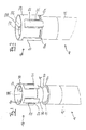
- Fig. 1 to 5 is a substantially cylindrical container for storing liquids in a section around one of the ends shown schematically and generally designated 10.
- the container 10 is formed by a substantially cylindrical shell 12, which widens at its one end face and forms a radially outwardly projecting annular flange 12a.
- the cylinder jacket 12 may be formed, for example, of glass or a plastic material.
- the container 10 has a circular opening 14 through which liquid into the container 10 is inserted or can be removed from the container 10.
- the opening 14 is closed by a cover member 18 of a closure assembly 16 according to the invention, in the state according to Fig. 2 and 4 towards the outlet of the liquid stored in the container 10 tight and beyond airtight to the environment.
- the lid member 18 is in its closed position.
- Fig. 1 and 5 a state in which liquid stored in the container 10 can escape through the opening 14 into the environment, since a gap 20 is now formed between the cover element 18 and the wall 12 of the container.
- Fig. 3 shows a state during the placement of the closure assembly on the opening 14.
- the closure assembly 16 in the insertion direction E (in the embodiment shown with open-top end along the axial direction of the cylinder down) moves until the cover member 18 in abutment with the container 10 passes and the closure assembly 16 associated clamping members 20 engage with the surrounding the opening ring flange 12a of the container 10.
- the closure arrangement of in Fig. 1 to 5 shown embodiment has a total of 4 clamping members, which are arranged at equal intervals of 90 ° around the circumference of the closure assembly around.
- Each tension member 20 is claw-shaped with an elongate claw body extending substantially along the insertion direction and attached to the closure assembly 16 at one end 20a thereof.
- the other end of the claw body is formed in the shape of a projection 20c which engages in the closed position with the annular flange 12a of the container 10.
- this engagement is not yet complete and the clamping members 20 are not exactly parallel, but at an acute angle to the insertion direction and are at its the projection 20c bearing end radially outward.
- the cover element 18 comprises a central circular cover wall 24, which extends substantially transversely to the cylinder axis, and an adjoining cylindrical guide wall 26, which in the in Fig. 2 and 4 shown closure position and in the position acc. Fig. 3 extends substantially annular parallel to the wall 12 of the container 10 and rests against the inside thereof.
- the top wall 24 and the guide wall 26 are at a right angle ⁇ to each other.
- annular flange 28 is formed, which at a right angle to the guide wall 26 radially outward protrudes and in the closed position under mediation of an O-ring 22 airtight the end wall of the container 10 is present.
- the cover element 18 merges integrally into a substantially annular closure housing 30 at the radially outer end of the annular flange 28.
- the closure housing 30 thus projects radially beyond the parts (cover wall 24, guide wall 26) of the cover element 18, which are inserted into the opening 14.
- the closure housing 30 abuts against the end wall of the container 10 and extends the container 10 in the direction of the cylinder axis.
- rectangular recesses 32 are recessed, which are arranged distributed in the circumferential direction at equal intervals. The recesses 32 extend from the transition into the annular flange 28 end of the closure housing 30 in the axial direction.
- the clamping members 20 are received, in such a way that the clamping members 20 in its rest position, the closure housing 30 in the circumferential direction substantially continue, but extend in the axial direction to beyond the merging into the annular flange 28 edge of the closure housing 30 addition.
- the clamping members 20 extend corresponding to the recesses 32 in the direction of the axis of the closure housing 30 and thus substantially in the insertion direction. They are attached at their one end 20 a to the axial edge of the respective recess 32 forming portion of the closure housing 30, wherein it is about an axis tangential to the circumferential direction and orthogonal to the axis of the closure housing 30 against a bias, they in their the closure housing 30 continuing Rest position repels, are deflectable. Between the two ends 20a and 20c, the clamping members 20 are provided on their inner sides, each with an inwardly protruding thickening 20b. This thickening, which projects beyond the inner wall of the closure housing 30 into the receptacle in the resting state of the clamping members 20, forms a contact section for an actuating member.
- Both the cover element 18 and the closure housing 30 together with clamping members 20 are formed from a hard thermoplastic material, for example polyethylene (PE), polypropylene (PP) or polyamide (PA).
- PE polyethylene
- PP polypropylene
- PA polyamide
- the closure housing 30 encloses a receptacle 32 formed substantially in the shape of a stepped cylinder, which extends down to the top wall 24.
- the receptacle 32 is open towards the side facing away from the cover element 18 in the axial direction and structured on its inner circumference such that a coupling projection 40 of a pipetting unit (see FIG. Fig. 5 ), which belongs to the head of an automatic pipetting device, can be inserted from the end facing away from the cover element 18 into the receptacle 32 and in an in Fig. 5 shown insertion position in the receptacle 32 is fixed.
- This purpose is served in particular by a Fig. 5 indicated O-ring 42, which in the docking position of the coupling lug 40 according to Fig. 5 on the inside of the receptacle 32 surrounding peripheral wall of the closure housing 30 is present.
- the closure housing 30 is first inserted with the lid member 18 provided therein in the circular opening 14 at the front end of the container 10 and pushed in the insertion direction E in so far into the opening until the annular flange 28 and the O-ring 22 comes into contact with the annular flange 12a at the end wall of the container 10.
- This condition in Fig. 3 is shown, can be achieved both with the aid of an inserted into the receptacle 32 actuator and can be achieved in an empty recording by simply plugging the closure housing 30 and manual displacement of the closure housing 30 in the direction of insertion.
- the inwardly projecting projection 20c provided on the lower end of the clamping members 20 in the figures is formed with an insertion bevel at its radially inner end. He can thus on movement of the closure housing 30 in the insertion direction slide over the radially outermost point of the annular flange 28, wherein the clamping members 20 are deflected slightly outwards and thereby placed under bias.
- the engagement of the projections 20c of the clamping members 20 must first be solved with the annular flange 12a at the front end of the container 10.
- the lower ends of the clamping members 20, in which the projections 20c are formed must be deflected radially outward in the figures. This is done with the aid of the already mentioned coupling attachment 40 of a pipetting unit.
- the coupling lug 40 is retracted into the receptacle 32 of the closure assembly and locked there to an axial stop. In this docking position, the in Fig.
- the coupling lug 40 makes it possible, via a mechanism not shown in detail (see the EP 1 171 240 B2 , which shows an example of such a mechanism and to which reference is expressly made) in the axial direction, ie in the Fig. 5 shown state, in the insertion direction E directed force on the O-ring 42 exercise and concomitantly squeeze the O-ring 42.
- the O-ring 42 reacts with an increase in its circumference and therefore pushes the Clamping elements 20 at the attack portions 20b radially outward.
- With sufficient squeezing of the O-ring 42 then pass the projections 20c out of engagement with the annular flange 12a and the closure assembly can completely from the opening 14 in the in Fig. 5 indicated decrease direction A are removed.
- the decrease can be done in a simple manner by moving the robot arm on which the coupling lug 40 is provided because the crushed O-ring 42 is not only applied to the engaging portions 20b of the clamping members 20, but is pressed from the inside against the inner wall of the closure housing 30 ,
Landscapes
- Health & Medical Sciences (AREA)
- Chemical & Material Sciences (AREA)
- Analytical Chemistry (AREA)
- General Health & Medical Sciences (AREA)
- Hematology (AREA)
- Clinical Laboratory Science (AREA)
- Chemical Kinetics & Catalysis (AREA)
- Closures For Containers (AREA)
Priority Applications (1)
| Application Number | Priority Date | Filing Date | Title |
|---|---|---|---|
| EP07015902A EP2030687A1 (fr) | 2007-08-13 | 2007-08-13 | Dispositif de fermeture doté d'un mécanisme à déclic |
Applications Claiming Priority (1)
| Application Number | Priority Date | Filing Date | Title |
|---|---|---|---|
| EP07015902A EP2030687A1 (fr) | 2007-08-13 | 2007-08-13 | Dispositif de fermeture doté d'un mécanisme à déclic |
Publications (1)
| Publication Number | Publication Date |
|---|---|
| EP2030687A1 true EP2030687A1 (fr) | 2009-03-04 |
Family
ID=38951713
Family Applications (1)
| Application Number | Title | Priority Date | Filing Date |
|---|---|---|---|
| EP07015902A Withdrawn EP2030687A1 (fr) | 2007-08-13 | 2007-08-13 | Dispositif de fermeture doté d'un mécanisme à déclic |
Country Status (1)
| Country | Link |
|---|---|
| EP (1) | EP2030687A1 (fr) |
Cited By (4)
| Publication number | Priority date | Publication date | Assignee | Title |
|---|---|---|---|---|
| WO2014151996A3 (fr) * | 2013-03-14 | 2014-12-04 | Gen-Probe Incorporated | Systèmes, procédés et appareils pour effectuer des dosages automatisés à base de réactif |
| JP2019068860A (ja) * | 2013-03-14 | 2019-05-09 | ジェン−プローブ・インコーポレーテッド | 診断システムおよび方法 |
| CN112105934A (zh) * | 2018-05-22 | 2020-12-18 | 株式会社日立高新技术 | 自动分析装置 |
| WO2021101550A1 (fr) * | 2019-11-21 | 2021-05-27 | Hamilton Company | Dispositif de pipetage, élément d'accouplement de pointe de pipette, et pointe de pipette : dispositifs et procédés |
Citations (4)
| Publication number | Priority date | Publication date | Assignee | Title |
|---|---|---|---|---|
| EP0333967A1 (fr) * | 1988-03-25 | 1989-09-27 | DEMATEX DEVELOPMENT & TRADING INC. c/o QUIJANO AND ASSOCIATES | Tube, bouchon et bague de compression pour systèmes de prise d'échantillon de sang |
| EP0676643A2 (fr) * | 1994-04-09 | 1995-10-11 | Roche Diagnostics GmbH | Système de réalisation sans contamination des réactions |
| WO2001060967A1 (fr) * | 2000-02-16 | 2001-08-23 | Bio-Nobile Oy | Procede d'ouverture et de fermeture d'une ouverture |
| EP1402952A1 (fr) * | 2002-09-26 | 2004-03-31 | Siemens Aktiengesellschaft | Cartouche avec moyen d' entrainement et système de manipulation |
-
2007
- 2007-08-13 EP EP07015902A patent/EP2030687A1/fr not_active Withdrawn
Patent Citations (5)
| Publication number | Priority date | Publication date | Assignee | Title |
|---|---|---|---|---|
| EP0333967A1 (fr) * | 1988-03-25 | 1989-09-27 | DEMATEX DEVELOPMENT & TRADING INC. c/o QUIJANO AND ASSOCIATES | Tube, bouchon et bague de compression pour systèmes de prise d'échantillon de sang |
| EP0676643A2 (fr) * | 1994-04-09 | 1995-10-11 | Roche Diagnostics GmbH | Système de réalisation sans contamination des réactions |
| US5846489A (en) * | 1994-04-09 | 1998-12-08 | Boehringer Mannheim Gmbh | System for opening closures of vessels and for the contamination-free operation of reaction sequences |
| WO2001060967A1 (fr) * | 2000-02-16 | 2001-08-23 | Bio-Nobile Oy | Procede d'ouverture et de fermeture d'une ouverture |
| EP1402952A1 (fr) * | 2002-09-26 | 2004-03-31 | Siemens Aktiengesellschaft | Cartouche avec moyen d' entrainement et système de manipulation |
Cited By (39)
| Publication number | Priority date | Publication date | Assignee | Title |
|---|---|---|---|---|
| CN110180609B (zh) * | 2013-03-14 | 2023-02-24 | 简·探针公司 | 用于执行自动试剂分析的系统、方法和设备 |
| USD857883S1 (en) | 2013-03-14 | 2019-08-27 | Gen-Probe Incorporated | Receptacle |
| US20160008810A1 (en) * | 2013-03-14 | 2016-01-14 | Gen-Probe Incorporated | Interlocking cap and receptacle for automated processes |
| CN105283249A (zh) * | 2013-03-14 | 2016-01-27 | 简·探针公司 | 用于执行自动试剂分析的系统、方法和设备 |
| US9248449B2 (en) | 2013-03-14 | 2016-02-02 | Gen-Probe Incorporated | Interlocking cap and receptacle with detent feature |
| JP2016518588A (ja) * | 2013-03-14 | 2016-06-23 | ジェン−プローブ・インコーポレーテッド | 自動化された試薬ベースの分析を行うためのシステム、方法、および装置 |
| US9527080B2 (en) | 2013-03-14 | 2016-12-27 | Gen-Probe Incorporated | Fluid cartridge |
| JP2017072614A (ja) * | 2013-03-14 | 2017-04-13 | ジェン−プローブ・インコーポレーテッド | 自動化された試薬ベースの分析を行うためのシステム、方法、および装置 |
| JP2017072615A (ja) * | 2013-03-14 | 2017-04-13 | ジェン−プローブ・インコーポレーテッド | 自動化された試薬ベースの分析を行うためのシステム、方法、および装置 |
| US9630179B2 (en) | 2013-03-14 | 2017-04-25 | Gen-Probe Incorporated | Fluid cartridge |
| AU2016247157B2 (en) * | 2013-03-14 | 2017-11-09 | Gen-Probe Incorporated | Systems, methods, and apparatuses for performing automated reagent-based assays |
| US10159981B2 (en) | 2013-03-14 | 2018-12-25 | Gen-Probe Incorporated | Plastic body configured for engagement with an automated receptacle transport mechanism |
| CN105283249B (zh) * | 2013-03-14 | 2019-01-11 | 简·探针公司 | 用于执行自动试剂分析的系统、方法和设备 |
| JP2019068860A (ja) * | 2013-03-14 | 2019-05-09 | ジェン−プローブ・インコーポレーテッド | 診断システムおよび方法 |
| JP2019068859A (ja) * | 2013-03-14 | 2019-05-09 | ジェン−プローブ・インコーポレーテッド | 診断システムおよび方法 |
| JP2019071906A (ja) * | 2013-03-14 | 2019-05-16 | ジェン−プローブ・インコーポレーテッド | 診断システムおよび方法 |
| US10889851B2 (en) | 2013-03-14 | 2021-01-12 | Gen-Probe Incorporated | Method for moving a processing vial between locations of an instrument |
| CN110180609A (zh) * | 2013-03-14 | 2019-08-30 | 简·探针公司 | 用于执行自动试剂分析的系统、方法和设备 |
| US9162228B2 (en) | 2013-03-14 | 2015-10-20 | Gen-Probe Incorporated | Interlocking cap and receptacle for automated processes |
| US12442033B2 (en) | 2013-03-14 | 2025-10-14 | Gen-Probe Incorporated | Method for receiving and storing reagent packs in an instrument |
| US11279967B2 (en) | 2013-03-14 | 2022-03-22 | Gen-Probe Incorporated | System and method for conducting an assay |
| US12173352B2 (en) | 2013-03-14 | 2024-12-24 | Gen-Probe Incorporated | Method for receiving and storing reagent packs in an instrument |
| US11136617B2 (en) | 2013-03-14 | 2021-10-05 | Gen-Probe Incorporated | Interlocking cap and vial |
| US10975416B2 (en) | 2013-03-14 | 2021-04-13 | Gen-Probe Incorporated | Method for processing the contents of a processing vial within an instrument |
| US11292003B2 (en) | 2013-03-14 | 2022-04-05 | Gen-Probe Incorporated | Method and apparatus for separating interlocked cap and receptacle |
| US11420207B2 (en) | 2013-03-14 | 2022-08-23 | Gen-Probe Incorporated | Reaction receptacle |
| US11434521B2 (en) | 2013-03-14 | 2022-09-06 | Gen-Probe Incorporated | Method for conducting an assay |
| WO2014151996A3 (fr) * | 2013-03-14 | 2014-12-04 | Gen-Probe Incorporated | Systèmes, procédés et appareils pour effectuer des dosages automatisés à base de réactif |
| US11732288B2 (en) | 2013-03-14 | 2023-08-22 | Gen-Probe Incorporated | Assembly having reagent pack loading station |
| US11732289B2 (en) | 2013-03-14 | 2023-08-22 | Gen-Probe Incorporated | Receptacle distribution system |
| US11746373B2 (en) | 2013-03-14 | 2023-09-05 | Gen-Probe Incorporated | Processing vial and cap |
| US11761026B2 (en) | 2013-03-14 | 2023-09-19 | Gen-Probe Incorporated | Diagnostic system and method |
| US11761027B2 (en) | 2013-03-14 | 2023-09-19 | Gen-Probe Incorporated | System and method for receiving and storing reagent packs in an instrument |
| US11788115B2 (en) | 2013-03-14 | 2023-10-17 | Gen-Probe Incorporated | Interlocking cap and vial |
| US11834701B2 (en) | 2013-03-14 | 2023-12-05 | Gen-Probe Incorporated | Reagent pack changer |
| US12110535B2 (en) | 2013-03-14 | 2024-10-08 | Gen-Probe Incorporated | Method for reconstituting a reagent |
| CN112105934B (zh) * | 2018-05-22 | 2024-05-14 | 株式会社日立高新技术 | 自动分析装置 |
| CN112105934A (zh) * | 2018-05-22 | 2020-12-18 | 株式会社日立高新技术 | 自动分析装置 |
| WO2021101550A1 (fr) * | 2019-11-21 | 2021-05-27 | Hamilton Company | Dispositif de pipetage, élément d'accouplement de pointe de pipette, et pointe de pipette : dispositifs et procédés |
Similar Documents
| Publication | Publication Date | Title |
|---|---|---|
| DE69808639T2 (de) | Kupplungsanordnung für eine flüssigkeitsverbindung | |
| AT500459A1 (de) | Verfahren zum zusammenbau einer kappe mit einem aufnahmebehälter | |
| EP0604748B1 (fr) | Manchon de trocart | |
| AT514833B1 (de) | Abnahmebaugruppe, insbesondere für Blutproben | |
| DE102008051351A1 (de) | Verschluss zum Aufpressen und Verrasten mit einem Behälter | |
| EP0679380A1 (fr) | Dispositif de transfert et de prélèvement de fluides hors de bouteilles, poches ou récipients similaires dans un but médical | |
| EP1454650A1 (fr) | Dispositif de transfer, notamment pour des fluides médicaux | |
| EP2651471A1 (fr) | Dispositif permettant de prélever du liquide contenu dans un récipient | |
| EP1792657B1 (fr) | Récipient avec couvercle | |
| EP3384219B1 (fr) | Bouchon de récipient destiné à être utilisé lors de la lyophilisation | |
| EP0756338A1 (fr) | Montage de bouchon pour fermer d'ouvertures individuelles de cellules d'accumulateur | |
| DE69909618T2 (de) | Mehrkammerbehälter | |
| DE202015000521U1 (de) | Ausstoßventilanordnung für ein Flaschenaufsatzgerät | |
| EP1894555A2 (fr) | Dispositif pour l'extraction de liquides | |
| EP2030688A1 (fr) | Dispositif de fermeture à soufflet | |
| AT409725B (de) | Trennvorrichtung | |
| EP2069216B8 (fr) | Dispositif de fermeture pour un sac d'emballage, et emballage équipé d'un dispositif de fermeture | |
| EP1797920B1 (fr) | Dispositif apte à recevoir et à délivrer une substance fluide | |
| EP3137396B1 (fr) | Système de fermeture, procédé permettant de fermer une fermeture et conteneur de produits en vrac avec un tel système | |
| WO2017198711A1 (fr) | Récipient comprenant un espace de réception et procédé de prélèvement d'une substance présente dans l'espace de réception d'un récipient | |
| DE102006020286A1 (de) | Vorrichtung zur Entnahme von Flüssigkeiten | |
| DE3904428A1 (de) | Verschluesse fuer behaelter | |
| DE102023206095B3 (de) | Befülleinrichtung und Verfahren zum Befüllen einer Gaskartusche mit Druckgas oder Flüssiggas | |
| EP2006021A1 (fr) | Partie supérieure de pipetage | |
| AT516438A1 (de) | Handhabungsvorrichtung sowie Verfahren zu deren Herstellung |
Legal Events
| Date | Code | Title | Description |
|---|---|---|---|
| PUAI | Public reference made under article 153(3) epc to a published international application that has entered the european phase |
Free format text: ORIGINAL CODE: 0009012 |
|
| AK | Designated contracting states |
Kind code of ref document: A1 Designated state(s): AT BE BG CH CY CZ DE DK EE ES FI FR GB GR HU IE IS IT LI LT LU LV MC MT NL PL PT RO SE SI SK TR |
|
| AX | Request for extension of the european patent |
Extension state: AL BA HR MK RS |
|
| AKX | Designation fees paid | ||
| STAA | Information on the status of an ep patent application or granted ep patent |
Free format text: STATUS: THE APPLICATION IS DEEMED TO BE WITHDRAWN |
|
| 18D | Application deemed to be withdrawn |
Effective date: 20090905 |
|
| REG | Reference to a national code |
Ref country code: DE Ref legal event code: 8566 |