EP1402955B1 - Séparateur avec vidage automatique des particules solides dans un container et procédé d'operation d'un tel separateur - Google Patents
Séparateur avec vidage automatique des particules solides dans un container et procédé d'operation d'un tel separateur Download PDFInfo
- Publication number
- EP1402955B1 EP1402955B1 EP02021438A EP02021438A EP1402955B1 EP 1402955 B1 EP1402955 B1 EP 1402955B1 EP 02021438 A EP02021438 A EP 02021438A EP 02021438 A EP02021438 A EP 02021438A EP 1402955 B1 EP1402955 B1 EP 1402955B1
- Authority
- EP
- European Patent Office
- Prior art keywords
- solids
- separator
- tank
- auto
- collecting
- Prior art date
- Legal status (The legal status is an assumption and is not a legal conclusion. Google has not performed a legal analysis and makes no representation as to the accuracy of the status listed.)
- Expired - Lifetime
Links
Images

Classifications
-
- A—HUMAN NECESSITIES
- A01—AGRICULTURE; FORESTRY; ANIMAL HUSBANDRY; HUNTING; TRAPPING; FISHING
- A01J—MANUFACTURE OF DAIRY PRODUCTS
- A01J11/00—Apparatus for treating milk
- A01J11/10—Separating milk from cream
-
- B—PERFORMING OPERATIONS; TRANSPORTING
- B04—CENTRIFUGAL APPARATUS OR MACHINES FOR CARRYING-OUT PHYSICAL OR CHEMICAL PROCESSES
- B04B—CENTRIFUGES
- B04B11/00—Feeding, charging, or discharging bowls
- B04B11/04—Periodical feeding or discharging; Control arrangements therefor
Definitions
- the invention relates to a self-draining separator with a solids collecting device according to the preamble of claim 1 and a method for operating a self-draining separator with a solids collecting device.
- a solids catcher is known from the brochure "Solids Capture Tank for Milk Separators", 9910-8024-240, Westfalia Separator Food Tec GmbH, Oelde, Germany.
- the solid collecting container of the solids collecting device shown in this document serves to trap the solid phase during emptying of self-draining separators, in particular milk separators, and on the one hand enables the degradation of the high kinetic energy of the product phase emptied from the separator and, on the other hand, serves as a buffer container for a downstream solids pump.
- the solids collecting container is i.allg. arranged directly below the solids outlet of the separator and can be provided with one or more rod probes with which the liquid level in the solids collecting container can be measured.
- a more or less large solids collecting container is installed directly behind the separator of the separator, but the volume is significantly larger - e.g. 2 - 3 times as large - as the emptying volume of the separator is.
- the filling level is detected by one or more level sensors and used to control a drain pump.
- the solids collection containers are provided with vent pipes. These are located in the center and serve to divert the air blast during emptying operations.
- the diameter is adapted to the machine and container size. Also as overflow protection the vent pipe is used, so that, for example, in case of pump failure, the product can not back up into the separator.
- the solids collection containers have thus proven themselves, but bring u.a. the disadvantage of relatively high costs and a large space requirement due to their relatively large-volume design and a relatively high cleaning effort with it.
- DE 35 36 624 A1 shows a generic separator.
- the solids arrester is assigned a recirculation circuit with which the consistency of the solid in the solid collecting container can be determined.
- DE 38 41 634 A1 discloses a method for solids-dependent opening of the drum of a separator, in which the solids discharge is dependent on the solid batch in the drum.
- DE 41 004 482 shows a solid bowl screw centrifuge for the separation of solid-liquid mixtures, in particular for the thickening of thin sludge, wherein the discharge of all product phases takes place continuously. In the discharge, in particular, the flow rate of the derived flowable solid phase is determined. If its flowability is too thin, a portion of thin sludge from the product feed of the centrifuge is added directly to the discharged solid phase.
- the invention has the object to provide a self-emptying separator with a solids collecting device, which is inexpensive to produce and easy to clean and is also useful for monitoring the separator against this background.
- the invention solves this problem by the subject matter of claim 1 and the subject matter of claim 18. It is suitable for the processing of products in which the solid is still flowable.
- the solid collecting container can be made smaller and thus easier to clean.
- supplementary monitoring functions can also be realized in a simple manner.
- the volume of the solids collecting container is less than twice the volume of the volume of the separator drum. In particular, it corresponds to 0.8-1.2 times the volume. Particularly preferably, the volume of the solids collecting container corresponds to the volume of the separator drum. So there are very small and therefore inexpensive solid waste container used.
- the separator is preferably arranged above the solids collecting container and / or the container feed line is connected directly to a solids trap.
- a compensator to compensate for the oscillatory movements of the separator or for decoupling can be interposed.
- the container inlet opens into the upper region of the solids collecting container, in particular in the upper third, preferably tangentially, so that the kinetic energy is degraded particularly well during the circulation of the solid in the container.
- the container diameter also corresponds to the height of the container.
- the height is at least 0.5 times and at most 2 times the diameter.
- the function of the separator can be monitored by a control computer on the basis of the signals emitted by the measuring device, and operating or fault functions can be triggered.
- the duration of the emptying in particular the duration of the idling of the measuring device is taken into account. This should be subtracted from the total duration of the response of the measuring device to determine the discharge time.
- the time delay between the response of the measuring device and - preferably - the achievement of the valve of the venting / sewage path is taken into account when triggering operating or fault functions. This is - depending on the type of machine - at less than 0, 5 sec, between 0, 5 and 2, in particular between 0.5 and 1 sec.
- the solid phase leaves the separator at high speed and generates a pressure surge. Air is entrained and depressed before the phase and can be dissipated by the delayed circuit without product loss, because the air can first be diverted before the product reaches the valve before the gully.
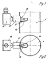
- Fig. 1 shows a solids collecting device which has a tangential container inlet 1, which the solids trap of a separator, not shown here -. a milk separator is connected downstream, which is preferably arranged above the solids container 3.
- the size of the here substantially cylindrical solids collecting container 3 is adapted to the maximum emptying volume of the separator during emptying and is e.g. in adaptation to the discharge volume 80 1.
- the height is measured in the cylindrical area.
- the solids collecting container 3 is thus significantly smaller - e.g. more than 50% - as the known solids collection container of the prior art.
- a measuring device 2 is arranged, which is shown in more detail in FIGS. 2 and 3.
- the container inlet 1 opens here horizontally tangentially into the upper region - here in the upper third - of the solids collecting container 3, which in turn has a tubular container outlet 4 at its conically configured underside in the center, which branches t-piece-like below the solids collecting container 3.
- An angled (for example obliquely from above) tangential opening of the container inlet 1 is likewise conceivable.
- the arrangement of the container outlet 4 in the center of the conically shaped bottom has the very special advantage that only fluid is dissipated with solids, the kinetic energy has degraded so far that they can flow through the center of the bottom. Separate vent pipes are no longer necessary.
- a solids pump 8 which is preferably designed as a self-priming centrifugal pump, is arranged, which in turn is arranged downstream of a tee-type branching pump discharge line 9.
- the tubular pump outlet 9 allows on the one hand via a solids valve 10, the derivation of the product phase in a solids discharge 11 and on the other hand via a product valve 12, the derivative of the product phase in the product return 13 of the separator.
- the measuring device 2 is shown in more detail in FIGS. 2 and 3.
- the collecting tray 14 is arranged in a region of the tubular container inlet 1 which extends vertically downwards and faces away from the container.
- A likewise in the container inlet 1 - in a right here downwardly oriented pipe portion of the inlet - protruding level probe 16 with a sensor head 18 which passes through the pipe wall of the container inlet 1 on a sleeve 17 and projects into the collecting tray 14, allows a sensing of the collecting tray 14 flowing through the product phase (eg by means of a capacitive probe, which senses the liquid in the drip tray 14).
- the drip tray 14 extends approximately over a third of the diameter of the container inlet 1 into this and covers only a smaller part of the cross-sectional area of this tube.
- the measuring device 2 must be such that it can be sensed with it whether the discharge pipe 4 passes through a solid phase derived from the separator.
- the measuring device is connected to a control and / or regulating device, not shown here, of the separator, the signals emitted by it can be used to control the separator and the collecting device.
- the solids capture device is operated as follows:
- valve 6 During operation of the separator, the valve 6 is kept open prior to a solids discharge in order to bleed the separator easily and to ensure in operation that the solid collecting container 3 is really empty. The valve 6 thus ensures a venting of the separator and a constant rinse water drain.
- the valve 6 When introducing a solids discharge, however, the valve 6 is closed and the solids pump 8 is started.
- the duration of the solids pump 8 depends on the volume of solids discharge of the separator.
- the measuring device 2 is arranged in the upper region of the tangentially entering into the solids collecting container 3 container inlet 1.
- the air turbulences prevailing here ensure that no faulty switching is triggered by foaming.
Landscapes
- Life Sciences & Earth Sciences (AREA)
- Animal Husbandry (AREA)
- Environmental Sciences (AREA)
- Centrifugal Separators (AREA)
- Cyclones (AREA)
- Gasification And Melting Of Waste (AREA)
Claims (28)
- Séparateur à vidage automatique avec un dispositif collecteur de matières solides qui est conçu de telle manière qu'une durée est réglée entre les vidages, le dispositif collecteur de matières solides comportant un récipient collecteur de matières solides (3) qui comporte une arrivée de récipient (1) raccordée au séparateur - en particulier à un séparateur pour le traitement d'un produit laitier -, caractérisé en ce qu'un dispositif de mesure (2) est placé dans l'arrivée de récipient (1) pour la détection d'une phase solide fluide traversant l'arrivée de récipient (1) hors du séparateur.
- Séparateur à vidage automatique avec un dispositif collecteur de matières solides selon la revendication 1, caractérisé en ce que le volume du récipient collecteur de matières solides (3) est inférieur à 1,5 fois le volume d'un vidage du tambour de séparateur.
- Séparateur à vidage automatique avec un dispositif collecteur de matières solides selon la revendication 2, caractérisé en ce que le volume du récipient collecteur de matières solides (3) correspond à 0,8 - 1,2 fois le volume d'un vidage du tambour de séparateur.
- Séparateur à vidage automatique avec un dispositif collecteur de matières solides selon la revendication 3, caractérisé en ce que le volume du récipient collecteur de matières solides (3) correspond au volume d'un vidage du tambour de séparateur.
- Séparateur à vidage automatique avec un dispositif collecteur de matières solides selon l'une quelconque des revendications précédentes, caractérisé en ce que le séparateur est placé au-dessus du récipient collecteur de matières solides (3) et/ou en ce que l'arrivée de récipient (1) est raccordée directement à un collecteur de matières solides.
- Séparateur à vidage automatique avec un dispositif collecteur de matières solides selon l'une quelconque des revendications précédentes, caractérisé en ce que l'arrivée de récipient (1) débouche dans la zone supérieure du récipient collecteur de matières solides (3).
- Séparateur à vidage automatique avec un dispositif collecteur de matières solides selon la revendication 6, caractérisé en ce que l'arrivée de récipient (1) débouche dans le tiers supérieur du récipient collecteur de matières solides (3).
- Séparateur à vidage automatique avec un dispositif collecteur de matières solides selon l'une quelconque des revendications précédentes, caractérisé en ce que l'arrivée de récipient (1) débouche tangentiellement dans le récipient collecteur de matières solides (3).
- Séparateur à vidage automatique avec un dispositif collecteur de matières solides selon l'une quelconque des revendications précédentes, caractérisé en ce que la hauteur du récipient correspond au moins à 0,5 fois et au plus à 2 fois le diamètre du récipient.
- Séparateur à vidage automatique avec un dispositif collecteur de matières solides selon la revendication 9, caractérisé en ce que le diamètre du récipient correspond à la hauteur du récipient.
- Séparateur à vidage automatique avec un dispositif collecteur de matières solides selon l'une quelconque des revendications précédentes, caractérisé en ce que le récipient collecteur de matières solides (3) comporte un branchement de récipient (4) dans sa zone inférieure, en particulier sur sa face inférieure.
- Séparateur à vidage automatique avec un dispositif collecteur de matières solides selon la revendication 11, caractérisé en ce que la face inférieure est conique et le branchement de récipient (4) est placé au centre de la face inférieure (4).
- Séparateur à vidage automatique avec un dispositif collecteur de matières solides selon l'une quelconque des revendications 11 ou 12, caractérisé en ce que le branchement de récipient (4) bifurque en forme de T en dessous du récipient collecteur de matières solides (3), une vanne (6) du passage de purge/d'eaux usées étant disposée dans une branche (5) du branchement de récipient collecteur de matières solides (4), à travers laquelle le produit peut être dirigé, de préférence, dans un égout (19).
- Séparateur à vidage automatique avec un dispositif collecteur de matières solides selon la revendication 13, caractérisé en ce qu'une pompe pour matières solides (8) est disposée dans la seconde branche (7) du branchement de récipient (4).
- Séparateur à vidage automatique avec un dispositif collecteur de matières solides selon la revendication 14, caractérisé en ce qu'un branchement de pompe (9) bifurquant en forme de T est monté en aval de la pompe pour matières solides (8).
- Séparateur à vidage automatique avec un dispositif collecteur de matières solides selon la revendication 15, caractérisé en ce que le branchement de pompe (9) débouche, d'une part, dans un branchement pour matières solides (11) par l'intermédiaire d'une vanne pour matières solides (10) et, d'autre part, dans l'arrivée de produit (13) du séparateur par l'intermédiaire d'une vanne pour produit (12) ou dans un autre récipient devant le séparateur.
- Séparateur à vidage automatique avec un dispositif collecteur de matières solides selon l'une quelconque des revendications précédentes, caractérisé en ce qu'une cuvette collectrice (14) est disposée dans une zone de l'arrivée de récipient tubulaire (1) s'étendant, de préférence, perpendiculairement vers le bas.
- Procédé pour faire fonctionner un séparateur à vidage automatique avec un dispositif collecteur de matières solides qui est conçu de telle manière qu'une durée est réglée entre les vidages, le dispositif collecteur de matières solides comportant un récipient collecteur de matières solides (3) qui comporte une arrivée de récipient (1) raccordée au séparateur - en particulier à un séparateur pour le traitement d'un produit laitier -, un dispositif de mesure (2) étant placé dans l'arrivée de récipient (1) pour la détection d'une phase solide fluide traversant l'arrivée de récipient (1) hors du séparateur, caractérisé en ce qu'une phase solide fluide traversant l'arrivée de récipient (1) hors du séparateur est détectée avec le dispositif de mesure (2) placé dans l'arrivée de récipient (1) du dispositif collecteur de matières solides.
- Procédé selon la revendication 18, caractérisé en ce que le fonctionnement du séparateur est contrôlé par un ordinateur de commande et les fonctions de marche ou de panne sont déclenchées à l'aide de signaux émis par le dispositif de mesure.
- Procédé selon l'une quelconque des revendications 18 ou 19, caractérisé en ce que la durée réglée entre les vidages est contrôlée.
- Procédé selon l'une quelconque des revendications 18 à 20, caractérisé en ce que l'instant du démarrage, la durée et/ou le volume du vidage est déterminé à l'aide du dispositif de mesure (2) et en ce que, en cas d'écarts par rapport à des valeurs de consigne, une fonction d'avertissement et/ou de panne est déclenchée.
- Procédé selon la revendication 21, caractérisé en ce que la durée de la marche à vide du dispositif de mesure est prise en compte pour la détermination de la durée de vidage.
- Procédé selon l'une quelconque des revendications 18 à 22, caractérisé en ce qu'une purge est réalisée au moyen du branchement de récipient sur la face inférieure du récipient.
- Procédé selon l'une quelconque des revendications 18 à 23, caractérisé en ce que, lors du déclenchement des fonctions d'avertissement ou de panne, la temporisation entre la réaction du dispositif de mesure et l'arrivée à la vanne du passage de purge/d'eaux usées est prise en compte.
- Procédé selon la revendication 24, caractérisé en ce qu'une temporisation inférieure à 0,5 seconde ou entre 0,5 et 2 secondes, en particulier entre 0,5 et 1 seconde, est prise en compte.
- Procédé selon l'une quelconque des revendications 18 à 25, caractérisé en ce que, lors d'un vidage du séparateur, la vanne du passage de purge/d'eaux usées se ferme, la pompe pour matières solides (8) démarre et la vanne pour matières solides (10) s'ouvre.
- Procédé selon l'une quelconque des revendications 18 à 26, caractérisé en ce que, en cas de panne - comme par exemple, un débordement incontrôlé ou une ouverture involontaire du tambour ou un débordement du tambour -, la vanne (6) du passage de purge/d'eaux usées se ferme, la pompe pour matières solides (8) démarre, la vanne pour produit (12) s'ouvre et le produit est recyclé par pompage devant le séparateur.
- Procédé pour faire fonctionner un dispositif collecteur de matières solides selon l'une quelconque des revendications 18 à 27, caractérisé en ce que, en cas de fonctionnement sans panne entre les vidages, la vanne (6) du passage de purge/d'eaux usées est ouverte et la pompe pour matières solides (8) est arrêtée.
Priority Applications (3)
| Application Number | Priority Date | Filing Date | Title |
|---|---|---|---|
| DE50210164T DE50210164D1 (de) | 2002-09-25 | 2002-09-25 | Selbstentleerender Separator mit einer Feststoffauffangvorrichtung und Verfahren zum Betrieb des Separators |
| EP02021438A EP1402955B1 (fr) | 2002-09-25 | 2002-09-25 | Séparateur avec vidage automatique des particules solides dans un container et procédé d'operation d'un tel separateur |
| AT02021438T ATE362400T1 (de) | 2002-09-25 | 2002-09-25 | Selbstentleerender separator mit einer feststoffauffangvorrichtung und verfahren zum betrieb des separators |
Applications Claiming Priority (1)
| Application Number | Priority Date | Filing Date | Title |
|---|---|---|---|
| EP02021438A EP1402955B1 (fr) | 2002-09-25 | 2002-09-25 | Séparateur avec vidage automatique des particules solides dans un container et procédé d'operation d'un tel separateur |
Publications (2)
| Publication Number | Publication Date |
|---|---|
| EP1402955A1 EP1402955A1 (fr) | 2004-03-31 |
| EP1402955B1 true EP1402955B1 (fr) | 2007-05-16 |
Family
ID=31970307
Family Applications (1)
| Application Number | Title | Priority Date | Filing Date |
|---|---|---|---|
| EP02021438A Expired - Lifetime EP1402955B1 (fr) | 2002-09-25 | 2002-09-25 | Séparateur avec vidage automatique des particules solides dans un container et procédé d'operation d'un tel separateur |
Country Status (3)
| Country | Link |
|---|---|
| EP (1) | EP1402955B1 (fr) |
| AT (1) | ATE362400T1 (fr) |
| DE (1) | DE50210164D1 (fr) |
Cited By (1)
| Publication number | Priority date | Publication date | Assignee | Title |
|---|---|---|---|---|
| CN101554541B (zh) * | 2009-04-03 | 2012-11-28 | 江苏工业学院 | 一种多相流分离的复合t形管分离器及其分离方法 |
Family Cites Families (5)
| Publication number | Priority date | Publication date | Assignee | Title |
|---|---|---|---|---|
| DE3536624A1 (de) * | 1985-10-15 | 1987-04-16 | Kloeckner Humboldt Deutz Ag | Verfahren und vorrichtung zur steuerung des feststoff- oder dickstoffaustrages aus einem separator |
| DD266511A1 (de) * | 1987-12-22 | 1989-04-05 | Kyffhaeuserhuette Maschf | Verfahren zum feststoffabhaengigen oeffnen eines zentrifugalseparators |
| DE4002073C1 (fr) * | 1990-01-25 | 1991-05-02 | Horst 2190 Cuxhaven De Schliemann | |
| DE4104482A1 (de) * | 1991-02-14 | 1992-08-20 | Kloeckner Humboldt Deutz Ag | Einrichtung zur trennung von feststoff-fluessigkeitsgemischen |
| DE10135073C2 (de) * | 2001-07-18 | 2003-11-27 | Westfalia Separator Ag | Verfahren und Vorrichtung zur Überwachung und Steuerung/Regelung einer Zentrifuge |
-
2002
- 2002-09-25 AT AT02021438T patent/ATE362400T1/de not_active IP Right Cessation
- 2002-09-25 DE DE50210164T patent/DE50210164D1/de not_active Expired - Lifetime
- 2002-09-25 EP EP02021438A patent/EP1402955B1/fr not_active Expired - Lifetime
Cited By (1)
| Publication number | Priority date | Publication date | Assignee | Title |
|---|---|---|---|---|
| CN101554541B (zh) * | 2009-04-03 | 2012-11-28 | 江苏工业学院 | 一种多相流分离的复合t形管分离器及其分离方法 |
Also Published As
| Publication number | Publication date |
|---|---|
| EP1402955A1 (fr) | 2004-03-31 |
| ATE362400T1 (de) | 2007-06-15 |
| DE50210164D1 (de) | 2007-06-28 |
Similar Documents
| Publication | Publication Date | Title |
|---|---|---|
| DE69306433T2 (de) | Abscheider fester Partikel für den variablen Abzug von Flüssigkeitsströmen in einem zahnärztlichen Apparat | |
| DE69507544T2 (de) | System und Verfahren zum Sammeln von flüssigem Schneidefluidum und Spänen | |
| EP2348894B2 (fr) | Procédé permettant de réduire la teneur en pulpe de jus de fruits pulpeux | |
| EP3914372B1 (fr) | Installation de séparation eau-huile-boue | |
| EP2148563B1 (fr) | Procédé et dispositif de détermination de quantités lors du transfert d'un liquide | |
| GB2438076A (en) | Rotary screen drum | |
| EP3060352B1 (fr) | Procédé de clarification d'un produit fluide au moyen d'une centrifugeuse | |
| EP1818166A2 (fr) | Dispositif destiné au drainage de déchets et élimination d'autres parties liquides des déchets | |
| EP1402955B1 (fr) | Séparateur avec vidage automatique des particules solides dans un container et procédé d'operation d'un tel separateur | |
| EP0300439B1 (fr) | Dispositif de séparation de particules solides fines | |
| DE102008047122A1 (de) | Vorrichtung zur Abgabe von Flüssigkeit aus einem Tank und Verfahren zur Restentleerung eines Leitungsabschnittes | |
| EP1990317B1 (fr) | Procédé destiné au fonctionnement d'une station d'épuration, ainsi que station d'épuration | |
| EP3120908B1 (fr) | Procede et dispositif destines a la surveillance d'un separateur | |
| EP3705457B1 (fr) | Installation de nettoyage, en particulier pour eaux usées, permettant de séparer un liquide léger et/ou des graisses et procédé de fonctionnement de cette installation de nettoyage | |
| DE29800834U1 (de) | Vakuumtoilettensystem | |
| EP2078702B1 (fr) | Appareil et procédé discontinu de nettoyage des eaux usées | |
| DE3842860C2 (de) | Verfahren zum Behandeln von mit emulgierten Leichtflüssigkeiten beladenen Abwässern mit zusätzlicher Zwischenstufe | |
| KR101495905B1 (ko) | 모래여과의 안정성이 향상된 협잡물 처리기 | |
| WO2018054737A1 (fr) | Dispositif de traitement d'eaux grises pour véhicule ferroviaire | |
| DE4012419C2 (fr) | ||
| EP4414637B1 (fr) | Installation pour l'évacuation d'eaux usées, en particulier par aspiration sous vide | |
| DE102020131701A1 (de) | Verfahren zur Bestimmung des Umfangs an Verschmutzungen innerhalb einer Trommel eines Separators sowie ein Separator | |
| JPH0630254Y2 (ja) | スクリーン周り計装装置 | |
| DE102006030905B3 (de) | Verfahren zur Abscheidung von Verunreinigungen aus einer Faserstoffsuspension | |
| EP3546430B1 (fr) | Dispositif et procédé de surveillance de l'efficacité d'une unité de traitement de l'eau |
Legal Events
| Date | Code | Title | Description |
|---|---|---|---|
| PUAI | Public reference made under article 153(3) epc to a published international application that has entered the european phase |
Free format text: ORIGINAL CODE: 0009012 |
|
| 17P | Request for examination filed |
Effective date: 20030627 |
|
| AK | Designated contracting states |
Kind code of ref document: A1 Designated state(s): AT BE BG CH CY CZ DE DK EE ES FI FR GB GR IE IT LI LU MC NL PT SE SK TR |
|
| AX | Request for extension of the european patent |
Extension state: AL LT LV MK RO SI |
|
| AKX | Designation fees paid |
Designated state(s): AT BE BG CH CY CZ DE DK EE ES FI FR GB GR IE IT LI LU MC NL PT SE SK TR |
|
| 17Q | First examination report despatched |
Effective date: 20030908 |
|
| GRAP | Despatch of communication of intention to grant a patent |
Free format text: ORIGINAL CODE: EPIDOSNIGR1 |
|
| RTI1 | Title (correction) |
Free format text: AUTO-DISCHARGING SEPARATOR WITH COLLECTING DEVICE AND METHOD FOR OPERATING THE SEPARATOR |
|
| GRAS | Grant fee paid |
Free format text: ORIGINAL CODE: EPIDOSNIGR3 |
|
| GRAA | (expected) grant |
Free format text: ORIGINAL CODE: 0009210 |
|
| AK | Designated contracting states |
Kind code of ref document: B1 Designated state(s): AT BE BG CH CY CZ DE DK EE ES FI FR GB GR IE IT LI LU MC NL PT SE SK TR |
|
| PG25 | Lapsed in a contracting state [announced via postgrant information from national office to epo] |
Ref country code: FI Free format text: LAPSE BECAUSE OF FAILURE TO SUBMIT A TRANSLATION OF THE DESCRIPTION OR TO PAY THE FEE WITHIN THE PRESCRIBED TIME-LIMIT Effective date: 20070516 |
|
| REG | Reference to a national code |
Ref country code: GB Ref legal event code: FG4D Free format text: NOT ENGLISH |
|
| REG | Reference to a national code |
Ref country code: CH Ref legal event code: EP |
|
| REG | Reference to a national code |
Ref country code: IE Ref legal event code: FG4D Free format text: LANGUAGE OF EP DOCUMENT: GERMAN |
|
| REF | Corresponds to: |
Ref document number: 50210164 Country of ref document: DE Date of ref document: 20070628 Kind code of ref document: P |
|
| PG25 | Lapsed in a contracting state [announced via postgrant information from national office to epo] |
Ref country code: SE Free format text: LAPSE BECAUSE OF FAILURE TO SUBMIT A TRANSLATION OF THE DESCRIPTION OR TO PAY THE FEE WITHIN THE PRESCRIBED TIME-LIMIT Effective date: 20070816 |
|
| PG25 | Lapsed in a contracting state [announced via postgrant information from national office to epo] |
Ref country code: ES Free format text: LAPSE BECAUSE OF FAILURE TO SUBMIT A TRANSLATION OF THE DESCRIPTION OR TO PAY THE FEE WITHIN THE PRESCRIBED TIME-LIMIT Effective date: 20070827 |
|
| NLV1 | Nl: lapsed or annulled due to failure to fulfill the requirements of art. 29p and 29m of the patents act | ||
| GBV | Gb: ep patent (uk) treated as always having been void in accordance with gb section 77(7)/1977 [no translation filed] |
Effective date: 20070516 |
|
| REG | Reference to a national code |
Ref country code: IE Ref legal event code: FD4D |
|
| EN | Fr: translation not filed | ||
| PG25 | Lapsed in a contracting state [announced via postgrant information from national office to epo] |
Ref country code: NL Free format text: LAPSE BECAUSE OF FAILURE TO SUBMIT A TRANSLATION OF THE DESCRIPTION OR TO PAY THE FEE WITHIN THE PRESCRIBED TIME-LIMIT Effective date: 20070516 Ref country code: PT Free format text: LAPSE BECAUSE OF FAILURE TO SUBMIT A TRANSLATION OF THE DESCRIPTION OR TO PAY THE FEE WITHIN THE PRESCRIBED TIME-LIMIT Effective date: 20071016 Ref country code: DK Free format text: LAPSE BECAUSE OF FAILURE TO SUBMIT A TRANSLATION OF THE DESCRIPTION OR TO PAY THE FEE WITHIN THE PRESCRIBED TIME-LIMIT Effective date: 20070516 Ref country code: CZ Free format text: LAPSE BECAUSE OF FAILURE TO SUBMIT A TRANSLATION OF THE DESCRIPTION OR TO PAY THE FEE WITHIN THE PRESCRIBED TIME-LIMIT Effective date: 20070516 Ref country code: IE Free format text: LAPSE BECAUSE OF FAILURE TO SUBMIT A TRANSLATION OF THE DESCRIPTION OR TO PAY THE FEE WITHIN THE PRESCRIBED TIME-LIMIT Effective date: 20070516 Ref country code: BG Free format text: LAPSE BECAUSE OF FAILURE TO SUBMIT A TRANSLATION OF THE DESCRIPTION OR TO PAY THE FEE WITHIN THE PRESCRIBED TIME-LIMIT Effective date: 20070816 |
|
| PG25 | Lapsed in a contracting state [announced via postgrant information from national office to epo] |
Ref country code: SK Free format text: LAPSE BECAUSE OF FAILURE TO SUBMIT A TRANSLATION OF THE DESCRIPTION OR TO PAY THE FEE WITHIN THE PRESCRIBED TIME-LIMIT Effective date: 20070516 |
|
| PLBE | No opposition filed within time limit |
Free format text: ORIGINAL CODE: 0009261 |
|
| STAA | Information on the status of an ep patent application or granted ep patent |
Free format text: STATUS: NO OPPOSITION FILED WITHIN TIME LIMIT |
|
| BERE | Be: lapsed |
Owner name: WESTFALIA SEPARATOR A.G. Effective date: 20070930 |
|
| 26N | No opposition filed |
Effective date: 20080219 |
|
| PG25 | Lapsed in a contracting state [announced via postgrant information from national office to epo] |
Ref country code: IT Free format text: LAPSE BECAUSE OF FAILURE TO SUBMIT A TRANSLATION OF THE DESCRIPTION OR TO PAY THE FEE WITHIN THE PRESCRIBED TIME-LIMIT Effective date: 20070516 Ref country code: GB Free format text: LAPSE BECAUSE OF FAILURE TO SUBMIT A TRANSLATION OF THE DESCRIPTION OR TO PAY THE FEE WITHIN THE PRESCRIBED TIME-LIMIT Effective date: 20070516 Ref country code: GR Free format text: LAPSE BECAUSE OF FAILURE TO SUBMIT A TRANSLATION OF THE DESCRIPTION OR TO PAY THE FEE WITHIN THE PRESCRIBED TIME-LIMIT Effective date: 20070817 Ref country code: MC Free format text: LAPSE BECAUSE OF NON-PAYMENT OF DUE FEES Effective date: 20070930 |
|
| REG | Reference to a national code |
Ref country code: CH Ref legal event code: PL |
|
| PG25 | Lapsed in a contracting state [announced via postgrant information from national office to epo] |
Ref country code: FR Free format text: LAPSE BECAUSE OF FAILURE TO SUBMIT A TRANSLATION OF THE DESCRIPTION OR TO PAY THE FEE WITHIN THE PRESCRIBED TIME-LIMIT Effective date: 20080111 Ref country code: LI Free format text: LAPSE BECAUSE OF NON-PAYMENT OF DUE FEES Effective date: 20070930 Ref country code: CH Free format text: LAPSE BECAUSE OF NON-PAYMENT OF DUE FEES Effective date: 20070930 |
|
| PG25 | Lapsed in a contracting state [announced via postgrant information from national office to epo] |
Ref country code: BE Free format text: LAPSE BECAUSE OF NON-PAYMENT OF DUE FEES Effective date: 20070930 |
|
| PG25 | Lapsed in a contracting state [announced via postgrant information from national office to epo] |
Ref country code: AT Free format text: LAPSE BECAUSE OF NON-PAYMENT OF DUE FEES Effective date: 20070925 |
|
| PG25 | Lapsed in a contracting state [announced via postgrant information from national office to epo] |
Ref country code: EE Free format text: LAPSE BECAUSE OF FAILURE TO SUBMIT A TRANSLATION OF THE DESCRIPTION OR TO PAY THE FEE WITHIN THE PRESCRIBED TIME-LIMIT Effective date: 20070516 |
|
| PG25 | Lapsed in a contracting state [announced via postgrant information from national office to epo] |
Ref country code: CY Free format text: LAPSE BECAUSE OF FAILURE TO SUBMIT A TRANSLATION OF THE DESCRIPTION OR TO PAY THE FEE WITHIN THE PRESCRIBED TIME-LIMIT Effective date: 20070516 |
|
| PG25 | Lapsed in a contracting state [announced via postgrant information from national office to epo] |
Ref country code: LU Free format text: LAPSE BECAUSE OF NON-PAYMENT OF DUE FEES Effective date: 20070925 |
|
| PG25 | Lapsed in a contracting state [announced via postgrant information from national office to epo] |
Ref country code: TR Free format text: LAPSE BECAUSE OF FAILURE TO SUBMIT A TRANSLATION OF THE DESCRIPTION OR TO PAY THE FEE WITHIN THE PRESCRIBED TIME-LIMIT Effective date: 20070516 |
|
| PGFP | Annual fee paid to national office [announced via postgrant information from national office to epo] |
Ref country code: DE Payment date: 20151001 Year of fee payment: 14 |
|
| REG | Reference to a national code |
Ref country code: DE Ref legal event code: R119 Ref document number: 50210164 Country of ref document: DE |
|
| PG25 | Lapsed in a contracting state [announced via postgrant information from national office to epo] |
Ref country code: DE Free format text: LAPSE BECAUSE OF NON-PAYMENT OF DUE FEES Effective date: 20170401 |