EP1403480A2 - Steuersystem für Verbrennungsmotor mit Katalysator zur Reinigung von Abgasen - Google Patents
Steuersystem für Verbrennungsmotor mit Katalysator zur Reinigung von Abgasen Download PDFInfo
- Publication number
- EP1403480A2 EP1403480A2 EP03003189A EP03003189A EP1403480A2 EP 1403480 A2 EP1403480 A2 EP 1403480A2 EP 03003189 A EP03003189 A EP 03003189A EP 03003189 A EP03003189 A EP 03003189A EP 1403480 A2 EP1403480 A2 EP 1403480A2
- Authority
- EP
- European Patent Office
- Prior art keywords
- cooling
- temperature
- engine
- catalyst
- cooling water
- Prior art date
- Legal status (The legal status is an assumption and is not a legal conclusion. Google has not performed a legal analysis and makes no representation as to the accuracy of the status listed.)
- Granted
Links
Images






Classifications
-
- F—MECHANICAL ENGINEERING; LIGHTING; HEATING; WEAPONS; BLASTING
- F02—COMBUSTION ENGINES; HOT-GAS OR COMBUSTION-PRODUCT ENGINE PLANTS
- F02P—IGNITION, OTHER THAN COMPRESSION IGNITION, FOR INTERNAL-COMBUSTION ENGINES; TESTING OF IGNITION TIMING IN COMPRESSION-IGNITION ENGINES
- F02P5/00—Advancing or retarding ignition; Control therefor
- F02P5/04—Advancing or retarding ignition; Control therefor automatically, as a function of the working conditions of the engine or vehicle or of the atmospheric conditions
- F02P5/145—Advancing or retarding ignition; Control therefor automatically, as a function of the working conditions of the engine or vehicle or of the atmospheric conditions using electrical means
- F02P5/15—Digital data processing
- F02P5/152—Digital data processing dependent on pinking
-
- F—MECHANICAL ENGINEERING; LIGHTING; HEATING; WEAPONS; BLASTING
- F01—MACHINES OR ENGINES IN GENERAL; ENGINE PLANTS IN GENERAL; STEAM ENGINES
- F01P—COOLING OF MACHINES OR ENGINES IN GENERAL; COOLING OF INTERNAL-COMBUSTION ENGINES
- F01P7/00—Controlling of coolant flow
- F01P7/14—Controlling of coolant flow the coolant being liquid
- F01P7/16—Controlling of coolant flow the coolant being liquid by thermostatic control
- F01P7/164—Controlling of coolant flow the coolant being liquid by thermostatic control by varying pump speed
-
- F—MECHANICAL ENGINEERING; LIGHTING; HEATING; WEAPONS; BLASTING
- F02—COMBUSTION ENGINES; HOT-GAS OR COMBUSTION-PRODUCT ENGINE PLANTS
- F02D—CONTROLLING COMBUSTION ENGINES
- F02D41/00—Electrical control of supply of combustible mixture or its constituents
- F02D41/02—Circuit arrangements for generating control signals
- F02D41/021—Introducing corrections for particular conditions exterior to the engine
- F02D41/0235—Introducing corrections for particular conditions exterior to the engine in relation with the state of the exhaust gas treating apparatus
- F02D41/024—Introducing corrections for particular conditions exterior to the engine in relation with the state of the exhaust gas treating apparatus to increase temperature of the exhaust gas treating apparatus
- F02D41/0255—Introducing corrections for particular conditions exterior to the engine in relation with the state of the exhaust gas treating apparatus to increase temperature of the exhaust gas treating apparatus to accelerate the warming-up of the exhaust gas treating apparatus at engine start
-
- F—MECHANICAL ENGINEERING; LIGHTING; HEATING; WEAPONS; BLASTING
- F02—COMBUSTION ENGINES; HOT-GAS OR COMBUSTION-PRODUCT ENGINE PLANTS
- F02P—IGNITION, OTHER THAN COMPRESSION IGNITION, FOR INTERNAL-COMBUSTION ENGINES; TESTING OF IGNITION TIMING IN COMPRESSION-IGNITION ENGINES
- F02P5/00—Advancing or retarding ignition; Control therefor
- F02P5/04—Advancing or retarding ignition; Control therefor automatically, as a function of the working conditions of the engine or vehicle or of the atmospheric conditions
- F02P5/145—Advancing or retarding ignition; Control therefor automatically, as a function of the working conditions of the engine or vehicle or of the atmospheric conditions using electrical means
- F02P5/15—Digital data processing
- F02P5/1502—Digital data processing using one central computing unit
- F02P5/1506—Digital data processing using one central computing unit with particular means during starting
-
- F—MECHANICAL ENGINEERING; LIGHTING; HEATING; WEAPONS; BLASTING
- F01—MACHINES OR ENGINES IN GENERAL; ENGINE PLANTS IN GENERAL; STEAM ENGINES
- F01P—COOLING OF MACHINES OR ENGINES IN GENERAL; COOLING OF INTERNAL-COMBUSTION ENGINES
- F01P2025/00—Measuring
- F01P2025/08—Temperature
- F01P2025/44—Outlet manifold temperature
-
- F—MECHANICAL ENGINEERING; LIGHTING; HEATING; WEAPONS; BLASTING
- F01—MACHINES OR ENGINES IN GENERAL; ENGINE PLANTS IN GENERAL; STEAM ENGINES
- F01P—COOLING OF MACHINES OR ENGINES IN GENERAL; COOLING OF INTERNAL-COMBUSTION ENGINES
- F01P2025/00—Measuring
- F01P2025/08—Temperature
- F01P2025/46—Engine parts temperature
-
- F—MECHANICAL ENGINEERING; LIGHTING; HEATING; WEAPONS; BLASTING
- F02—COMBUSTION ENGINES; HOT-GAS OR COMBUSTION-PRODUCT ENGINE PLANTS
- F02B—INTERNAL-COMBUSTION PISTON ENGINES; COMBUSTION ENGINES IN GENERAL
- F02B1/00—Engines characterised by fuel-air mixture compression
- F02B1/12—Engines characterised by fuel-air mixture compression with compression ignition
-
- Y—GENERAL TAGGING OF NEW TECHNOLOGICAL DEVELOPMENTS; GENERAL TAGGING OF CROSS-SECTIONAL TECHNOLOGIES SPANNING OVER SEVERAL SECTIONS OF THE IPC; TECHNICAL SUBJECTS COVERED BY FORMER USPC CROSS-REFERENCE ART COLLECTIONS [XRACs] AND DIGESTS
- Y02—TECHNOLOGIES OR APPLICATIONS FOR MITIGATION OR ADAPTATION AGAINST CLIMATE CHANGE
- Y02T—CLIMATE CHANGE MITIGATION TECHNOLOGIES RELATED TO TRANSPORTATION
- Y02T10/00—Road transport of goods or passengers
- Y02T10/10—Internal combustion engine [ICE] based vehicles
- Y02T10/12—Improving ICE efficiencies
-
- Y—GENERAL TAGGING OF NEW TECHNOLOGICAL DEVELOPMENTS; GENERAL TAGGING OF CROSS-SECTIONAL TECHNOLOGIES SPANNING OVER SEVERAL SECTIONS OF THE IPC; TECHNICAL SUBJECTS COVERED BY FORMER USPC CROSS-REFERENCE ART COLLECTIONS [XRACs] AND DIGESTS
- Y02—TECHNOLOGIES OR APPLICATIONS FOR MITIGATION OR ADAPTATION AGAINST CLIMATE CHANGE
- Y02T—CLIMATE CHANGE MITIGATION TECHNOLOGIES RELATED TO TRANSPORTATION
- Y02T10/00—Road transport of goods or passengers
- Y02T10/10—Internal combustion engine [ICE] based vehicles
- Y02T10/40—Engine management systems
Definitions
- the present invention relates to a control system for an internal combustion engine, which incorporates catalyst for purifying exhaust gas, and in particular to a technology of fast activation of catalyst for purification of exhaust gas from an internal combustion engine, by controlling an engine cooling system or the like.
- An object of the present invention is to provide a control system for an internal combustion engine, which can rationally control the warm-up of the internal combustion engine and the warm-up of catalyst in the order of priority during a cold start.
- a control system for an internal combustion engine incorporating catalyst for purifying exhaust gas therefrom which can control, during a cold start, a heat (cooling loss) transmitted from combustion gas to an engine block and a heat (heat radiation for cooling) transmitted from the engine block to engine cooling water, in order to aim for early warm-up of the catalyst.
- a system for controlling the cooling loss and the heat radiation for cooling so that the warm-up of the catalyst is preferential to the warm-up of the internal combustion engine while the engine and the catalyst are warmed up in a short time.
- the control of the cooling loss is made by controlling, for example, the ignition timing while the control of the heat radiation for cooling is made by controlling the flow rate of cooling water through the intermediary of a water pump. That is, in such a case that the temperature of the catalyst has not yet risen up to its activation temperature, retardation control of the ignition timing is made so as to decrease the cooling loss, and as well, control is made such that the flow rate of cooling water is decreased to zero or a value smaller than a normal value so as to decrease the heat radiation for cooling.
- the provision of a knock sensor for detecting knocking of the internal combustion engine is desirable so that the ignition timing can be retarded when the knock sensor detects a knock during ignition timing control. Further, the flow rate of the cooling water by the water pump can be increased in order to promote the warm-up of the internal combustion engine in a sure and safe manner.
- a temperature controller 101 carries out temperature control of the engine and catalyst (which is aim at purifying exhaust gas from the engine) so as to aim for early warm-up of both engine and catalyst during a cold start of the engine.
- the desired heat radiation for cooling is delivered to a cooling system controller 102 while the desired cooling loss is delivered to an engine controller 103 for controlling the combustion of the engine.
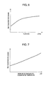
- Fig. 6 which shows an example of the relationship between the flow rate of the cooling water and the heat radiation for cooling
- the relationship between the flow rate and the heat radiation for cooling exhibits, the higher the flow rate, the greater the heat radiation for cooling.
- Fig. 7 which shows a relationship between the temperature of the cooling water and the heat radiation for cooling, if the temperature of the engine block is constant, the lower the temperature of the cooling water, the greater the heat radiation for cooling.
- the heat radiation for cooling can be controlled by a discharge quantity of the water pump or by a radiator for radiating a heat from the cooling water into the atmospheric air.
- Another feature of the present invention is the provision of the control for the heat radiation for cooling and the cooling loss in accordance with a temperature of the catalyst and a temperature of the cooling water.
- step 801 outputs from a catalyst temperature sensor, a water temperature sensor and the like are transmitted to the controller 101.
- the desired cooling loss is set to be maximum.
- the heat value transmitted to the engine block is increased, and further, since the heat radiation for cooling is minimized, the engine can be warmed up fast in comparison with a conventional one.
- the maximum control of the heat radiation for cooling will be described later. It is noted here that the maximum of the cooling loss corresponds to a maximum value in a controllable range.
- step 806 whether the water temperature is not lower than an overheat temperature at which there would be a risk of occurrence of seizure of the engine, or not is determined, and if it is true, step 805 is carried out, but if it is false, step 807 is carried out. At step 807, optimum fuel consumption control is carried out and the desired cooling loss is minimized.
- the desired cooling loss is in a controllable range, and it indicates a position of optimum spark advance (optimum spark ignition timing) as shown in Fig. 4 if the cooling loss is controlled only by the spark ignition timing.
- This optimum spark ignition timing enables the engine to operate with a high degree of efficiency.
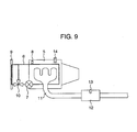
- Fig. 9 is a view which shows a configuration of the engine in this embodiment.
- a cooling system for an engine 5 is composed of a cooling water circulation passage 6, a water pump 7 for controlling heat radiation for cooling in the cooling system, a water temperature sensor 8 for measuring a temperature of cooling water, a radiator 9 for radiating heat from the cooling water into the atmospheric air, a radiator fan (which is not shown) for controlling the radiation of heat from the radiator into the atmospheric air, and a flow passage change-over valve (thermostat) 10 for introducing cooling water.
- a cooling water circulation passage 6 for controlling heat radiation for cooling in the cooling system
- a water temperature sensor 8 for measuring a temperature of cooling water
- a radiator 9 for radiating heat from the cooling water into the atmospheric air
- a radiator fan which is not shown
- a flow passage change-over valve (thermostat) 10 for introducing cooling water.
- catalyst 12 (3 way catalyst) for purifying exhaust gas and a catalyst sensor 13 for detecting a temperature of the catalyst are incorporated in an exhaust pipe 11 of the engine. Further, there is provided a knocking sensor 14 for detecting knocking of the engine.
- step 1001 outputs from the catalyst temperature sensor 13, the water temperature sensor 8 and the knocking sensor 14 are read.
- step 1002 whether a value detected by the catalyst temperature sensor 13 is not less than the activation temperature of the catalyst or not is determined, and if it is true, step 1004 is carried out, if it is false, step 1003 is carried out.
- step 1004 whether a value of engine cooling water detected by the water sensor 8 reaches the warm-up temperature of the engine 5 or not is determined, and if it is true, step 1006 is carried out, but if it is false step 1005 is carried out.
- step 1005 in order to warm up the engine 5, the ignition timing is advanced so as to raise the temperature of the engine cylinder. At this time, through the control of the cooling system, the stop and the operation of the water pump 7 are repeated or the discharge rate of the pump 7 is controlled to be minimum although it is operated.
- step 1006 it is determined that whether a value detected by the water temperature sensor or an estimated value of the temperature of the engine is not less than an overheat temperature at which the seizure of the engine is expected, or not. If it is true, step 1008 is carried out, but if it is false, step 1007 is carried out. At step 1007, control for minimizing the fuel consumption is carried out.
- the ignition is controlled at an ignition timing with which the cooling loss is minimized, and the pump is controlled so that the temperature of cooling water becomes not less than the warm-up temperature but not greater than the overheat temperature at which the seizure of the engine occurs.
- a temperature of the engine is estimated from the cooling loss and the heat radiation for cooling, and if the history of temperature of the engine exhibits an increase while the engine load is high, foreseeing control through which the flow rate of cooling water increases in advance may be carried out. In this foreseeing control, if the history of temperature of the engine exhibits a decrease while the engine load is low, the flow rate of cooling water is decreased in advance, or the circulation of cooling water into the radiator may be stopped.
- control upon overheating is carried out, that is, the flow rate of cooling water from the pump 7 and the output of the radiator are maximized so as to increase the heat radiation for cooling in order to prevent occurrence of seizure of the engine. Further, if the temperature is not lowered within a predetermined time after the above-mentioned controlled is carried out, the ignition timing is retarded so as to also decrease the cooling loss. Further, since the overheating is caused by any abnormality in the cooling system including the radiator and the pump, a warning lamp is turned on for indication of requirement for a fault diagnosis.
- a fault diagnosis for the radiator can be made in accordance with a speed of the radiator fan and a variation in the output of the water temperature sensor. Specifically, a correlation between the speed of the radiator fan and a variation in the output of the water temperature sensor is calculated, and if the thus calculated correlation is small, it can be determined that the radiator or the thermostat fails.
- Fig. 11 which shows an example of a time-chart in the case of execution of the warm-up control for both catalyst and engine, according to the present invention
- the ignition timing is retarded, and the pump is stopped so as to set the flow rate to zero.
- the ignition timing is advanced, and if knocking is detected, the ignition timing is retarded while the flow rate of the pump is increased in order to prevent occurrence of abnormal combustion.
- the pump After completion of the warm-up of the engine, the pump is operated in a steady-state, and also the ignition timing is reset to a normal position.
- Fig. 12 which shows control objectives of the flow rate in the control according to the present invention
- cooling water is blocked until the warm-up of the catalyst is completed so as to minimize the heat-radiation for cooling, and after completion of the warm-up of the catalyst, the flow rate of cooling water is controlled so as to be low as possible as it can until the warm-up of the engine is completed.
- the flow rate is controlled in accordance with a value of the heat radiation for cooling, thereby it is possible to optimumly materialize early warm-up of the catalyst and the engine.
- optimum early warm-up can be materialized by retarding the ignition timing at one and the same engine speed during warm-up of the catalyst but by advancing the ignition timing up to a knocking critical value during warm-up of the engine after completion of the warm-up of the catalyst, with respect to a normal ignition timing after completion of the warm-up. That is, if the ignition timing is retarded, after-burning is caused in exhaust gas discharged from the cylinder of the engine, and accordingly, the temperature of the exhaust gas becomes higher, thereby it is possible to aim for early warm-up. At this time, although the cooling loss is small, it is, more or less, greater than that with the normal ignition timing (efficiency drive) after completion of the warm-up.
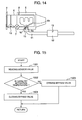
- Fig. 14 which shows the configuration of an engine in the second embodiment
- this configuration is the same as that shown in Fig. 9, except that there are provided a turbocharger 15 for supercharging the intake air in an exhaust pipe 11, a cooling passage 6a for cooling the turbocharger 15, a bypass passage 6b bypassing the cooling passage 6a, and a bypass valve 16 for blocking the flow in the bypass flow passage 6a.
- the cooling passage 6a and the bypass passage 6b are alternately connected to the engine cooling passage 6 through switching control of the bypass valve 16.
- a value from the catalyst temperature sensor 13 is read, and at step 1502, whether the temperature of the catalyst is greater than an activation temperature thereof or not is determined. If it is true, step 1504, the bypass valve 16 is closed (default). Meanwhile, it is false, at step 1503, the bypass valve 16 is opened so as to bypass cooling water flowing through the turbocharger 15 during warm-up of the catalyst.
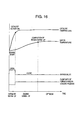
- Fig. 16 which shows a time-chart in the case of execution of the control according to the present invention
- the bypass valve 16 by opening the bypass valve 16, the lowering of the temperature of exhaust gas, which is caused when the exhaust gas passes through the turbocharger, can be minimized, thereby it is possible to fast warm-up the catalyst. It is noted that even during warm-up of the engine, if a relief valve for bypassing the flow of exhaust gas flowing into a turbo-turbine is closed, no cooling is required for the turbocharger, and accordingly, the bypass valve 16 may be opened.
- a value from the catalyst temperature sensor 13 is read, and at step 1802, whether the catalyst temperature is not less than its activation temperature or not is determined. If it is true, at step 1804, the shut-off valve 19 is opened, but if it is false, at step 1803, the shut-off valve 19 is closed.
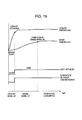
- Fig. 19 which shows a time-chart in the case of execution of the control according to the present invention
- the shut-off valve 19 is closed so as to shut-off the flow of cooling water flowing through the oil cooler 18 in order to decrease the heat radiation for cooling, and as a result, the exhaust temperature rises up, thereby it is possible to fast warm up the catalyst.
- the catalyst by controlling the cooling system in accordance with a catalyst temperature, the catalyst can be fast activated. Further, in combination of the control of the cooling system for the engine or the like with the control of the engine, the warm-up of the catalyst can be made prior to the warm-up of the engine while aiming at warming up both the catalyst and the engine.
- the present invention it is possible to reduce emission of exhaust gas due to early activation of the catalyst, and to improve the fuel consumption due to early warm-up of the internal combustion engine.
Landscapes
- Engineering & Computer Science (AREA)
- Chemical & Material Sciences (AREA)
- Combustion & Propulsion (AREA)
- Mechanical Engineering (AREA)
- General Engineering & Computer Science (AREA)
- Signal Processing (AREA)
- Theoretical Computer Science (AREA)
- Exhaust Gas After Treatment (AREA)
- Combined Controls Of Internal Combustion Engines (AREA)
- Electrical Control Of Ignition Timing (AREA)
Applications Claiming Priority (2)
| Application Number | Priority Date | Filing Date | Title |
|---|---|---|---|
| JP2002277379 | 2002-09-24 | ||
| JP2002277379A JP2004116310A (ja) | 2002-09-24 | 2002-09-24 | 内燃機関の制御装置 |
Publications (3)
| Publication Number | Publication Date |
|---|---|
| EP1403480A2 true EP1403480A2 (de) | 2004-03-31 |
| EP1403480A3 EP1403480A3 (de) | 2004-04-28 |
| EP1403480B1 EP1403480B1 (de) | 2007-08-08 |
Family
ID=31973246
Family Applications (1)
| Application Number | Title | Priority Date | Filing Date |
|---|---|---|---|
| EP03003189A Expired - Lifetime EP1403480B1 (de) | 2002-09-24 | 2003-02-19 | Steuersystem für Verbrennungsmotor mit Katalysator zur Reinigung von Abgasen |
Country Status (4)
| Country | Link |
|---|---|
| US (1) | US20040055283A1 (de) |
| EP (1) | EP1403480B1 (de) |
| JP (1) | JP2004116310A (de) |
| DE (1) | DE60315393T2 (de) |
Cited By (6)
| Publication number | Priority date | Publication date | Assignee | Title |
|---|---|---|---|---|
| WO2006075789A3 (en) * | 2005-01-13 | 2006-09-14 | Toyota Motor Co Ltd | Control apparatus and control method of internal combustion engine |
| WO2011042402A3 (de) * | 2009-10-06 | 2011-06-23 | Avl List Gmbh | Verfahren zum betreiben einer fremdgezündeten brennkraftmaschine |
| EP2829722A4 (de) * | 2012-03-19 | 2016-12-07 | Nissan Motor | Zündungszeitsteuervorrichtung für einen verbrennungsmotor |
| EP3101267A1 (de) * | 2015-06-05 | 2016-12-07 | Toyota Jidosha Kabushiki Kaisha | Steuerungsvorrichtung für verbrennungsmotor |
| EP3239505A4 (de) * | 2014-12-22 | 2018-01-03 | Yamaha Hatsudoki Kabushiki Kaisha | Luftgekühlte motoreinheit |
| EP3470638A1 (de) * | 2017-10-10 | 2019-04-17 | Volkswagen Aktiengesellschaft | Verfahren zum betreiben einer brennkraftmaschine, brennkraftmaschine und kraftfahrzeug |
Families Citing this family (29)
| Publication number | Priority date | Publication date | Assignee | Title |
|---|---|---|---|---|
| JP4404028B2 (ja) * | 2005-08-02 | 2010-01-27 | トヨタ自動車株式会社 | 内燃機関の制御装置 |
| JP5239198B2 (ja) * | 2007-04-06 | 2013-07-17 | トヨタ自動車株式会社 | 冷却システム制御装置 |
| US7797938B2 (en) * | 2007-07-31 | 2010-09-21 | Caterpillar Inc | Energy recovery system |
| JP4918898B2 (ja) * | 2007-09-12 | 2012-04-18 | トヨタ自動車株式会社 | 内燃機関 |
| DE102008008492B4 (de) * | 2008-02-11 | 2015-05-21 | Pierburg Gmbh | Verfahren zur Steuerung einer Kraftfahrzeug-Verbrennungsmotoranordnung |
| JP2010007569A (ja) * | 2008-06-27 | 2010-01-14 | Mazda Motor Corp | エンジンの冷却判定方法及びその判定システム |
| US7762232B2 (en) | 2008-11-06 | 2010-07-27 | Ford Global Technologies, Llc | Engine and exhaust heating for hybrid vehicle |
| US7950368B2 (en) * | 2008-11-06 | 2011-05-31 | Ford Global Technologies, Llc | Engine and exhaust heating |
| JP2010138746A (ja) * | 2008-12-10 | 2010-06-24 | Toyota Motor Corp | 内燃機関の制御システム |
| JP5120319B2 (ja) | 2009-04-03 | 2013-01-16 | 株式会社デンソー | エンジンの廃熱制御装置 |
| WO2010123787A2 (en) * | 2009-04-21 | 2010-10-28 | Borgwarner Inc. | A method for improving the light-off or regeneration behavior of an aftertreatment device in a vehicle system |
| US8612117B2 (en) | 2009-06-12 | 2013-12-17 | Denso Corporation | Apparatus for controlling the amount of waste heat of an engine |
| JP5353729B2 (ja) * | 2010-01-25 | 2013-11-27 | 三菱自動車工業株式会社 | エンジンの制御装置 |
| DE102010005831A1 (de) * | 2010-01-27 | 2011-07-28 | GM Global Technology Operations LLC, ( n. d. Ges. d. Staates Delaware ), Mich. | Abgasstrang für eine Brennkraftmaschine sowie Verfahren zum Betreiben einer Brennkraftmaschine |
| JP5384396B2 (ja) | 2010-02-15 | 2014-01-08 | 株式会社デンソー | エンジンの廃熱制御装置 |
| JP4865054B2 (ja) * | 2010-05-06 | 2012-02-01 | トヨタ自動車株式会社 | 電動式ウォーターポンプの制御装置 |
| JP5553041B2 (ja) * | 2011-02-04 | 2014-07-16 | 三菱自動車工業株式会社 | 内燃機関の制御装置 |
| JP2013032710A (ja) * | 2011-08-01 | 2013-02-14 | Toyota Motor Corp | 内燃機関の制御装置 |
| JP5892469B2 (ja) * | 2012-03-09 | 2016-03-23 | スズキ株式会社 | 車両用内燃機関の冷却装置 |
| US8955473B2 (en) * | 2013-02-27 | 2015-02-17 | Ford Global Technologies, Llc | Strategy for engine cold start emission reduction |
| SE539027C2 (sv) * | 2013-04-25 | 2017-03-21 | Scania Cv Ab | Förfarande och system för styrning av ett kylsystem |
| WO2014203312A1 (ja) | 2013-06-17 | 2014-12-24 | トヨタ自動車 株式会社 | 機関システムの冷却装置及びその制御方法 |
| JP2015059458A (ja) * | 2013-09-18 | 2015-03-30 | 日立オートモティブシステムズ株式会社 | クーリングシステムの制御装置 |
| JP6183170B2 (ja) * | 2013-11-15 | 2017-08-23 | いすゞ自動車株式会社 | エンジンの除熱量制御システム |
| US10590829B2 (en) | 2014-03-06 | 2020-03-17 | Hitachi Automotive Systems, Ltd. | Control device for internal combustion engine and control method for cooling device |
| JP2017089585A (ja) * | 2015-11-17 | 2017-05-25 | 日産自動車株式会社 | 車両の制御方法及び車両の制御装置 |
| KR101807046B1 (ko) * | 2016-04-01 | 2017-12-08 | 현대자동차 주식회사 | 냉각수온 센서를 구비한 엔진 냉각시스템 |
| GB2555864B (en) | 2016-11-15 | 2020-01-08 | Perkins Engines Co Ltd | Control system for thermal management of an engine aftertreatment device |
| JP7418936B2 (ja) * | 2021-10-01 | 2024-01-22 | ダイハツ工業株式会社 | 制御装置 |
Family Cites Families (7)
| Publication number | Priority date | Publication date | Assignee | Title |
|---|---|---|---|---|
| GB1406538A (en) * | 1972-01-25 | 1975-09-17 | Nissan Motor | Warming-up apparatus for internal combustion engine |
| JPS5218846B2 (de) * | 1973-01-29 | 1977-05-24 | ||
| DE4142120A1 (de) * | 1991-12-20 | 1993-06-24 | Porsche Ag | Kuehlwasserpumpe fuer eine brennkraftmaschine |
| US5390632A (en) * | 1992-02-19 | 1995-02-21 | Honda Giken Kogyo Kabushiki Kaisha | Engine cooling system |
| JP3337931B2 (ja) * | 1997-01-30 | 2002-10-28 | マツダ株式会社 | 筒内噴射式エンジン |
| DE10012432A1 (de) * | 2000-03-15 | 2001-09-20 | Volkswagen Ag | Abgasreinigungsanlage einer Verbrennungskraftmaschine mit einer Abgaskühlung und Verfahren zum Betrieb der Abgasreinigungsanlage |
| US6394051B1 (en) * | 2000-09-01 | 2002-05-28 | Ford Global Technologies, Inc. | Spark ignition engine with negative valve-overlap |
-
2002
- 2002-09-24 JP JP2002277379A patent/JP2004116310A/ja active Pending
-
2003
- 2003-02-19 DE DE60315393T patent/DE60315393T2/de not_active Expired - Fee Related
- 2003-02-19 EP EP03003189A patent/EP1403480B1/de not_active Expired - Lifetime
- 2003-02-26 US US10/372,817 patent/US20040055283A1/en not_active Abandoned
Cited By (11)
| Publication number | Priority date | Publication date | Assignee | Title |
|---|---|---|---|---|
| WO2006075789A3 (en) * | 2005-01-13 | 2006-09-14 | Toyota Motor Co Ltd | Control apparatus and control method of internal combustion engine |
| WO2011042402A3 (de) * | 2009-10-06 | 2011-06-23 | Avl List Gmbh | Verfahren zum betreiben einer fremdgezündeten brennkraftmaschine |
| EP2829722A4 (de) * | 2012-03-19 | 2016-12-07 | Nissan Motor | Zündungszeitsteuervorrichtung für einen verbrennungsmotor |
| EP3239505A4 (de) * | 2014-12-22 | 2018-01-03 | Yamaha Hatsudoki Kabushiki Kaisha | Luftgekühlte motoreinheit |
| EP3101267A1 (de) * | 2015-06-05 | 2016-12-07 | Toyota Jidosha Kabushiki Kaisha | Steuerungsvorrichtung für verbrennungsmotor |
| CN106246392A (zh) * | 2015-06-05 | 2016-12-21 | 丰田自动车株式会社 | 内燃机的控制装置 |
| RU2638228C2 (ru) * | 2015-06-05 | 2017-12-12 | Тойота Дзидося Кабусики Кайся | Управляющее устройство для двигателя внутреннего сгорания |
| CN106246392B (zh) * | 2015-06-05 | 2019-03-15 | 丰田自动车株式会社 | 内燃机的控制装置 |
| US10371115B2 (en) | 2015-06-05 | 2019-08-06 | Toyota Jidosha Kabushiki Kaisha | Control device for internal combustion engine |
| EP3470638A1 (de) * | 2017-10-10 | 2019-04-17 | Volkswagen Aktiengesellschaft | Verfahren zum betreiben einer brennkraftmaschine, brennkraftmaschine und kraftfahrzeug |
| US10871100B2 (en) | 2017-10-10 | 2020-12-22 | Volkswagen Aktiengesellschaft | Method for operating a combustion machine, combustion machine and motor vehicle |
Also Published As
| Publication number | Publication date |
|---|---|
| EP1403480A3 (de) | 2004-04-28 |
| JP2004116310A (ja) | 2004-04-15 |
| US20040055283A1 (en) | 2004-03-25 |
| DE60315393T2 (de) | 2008-05-08 |
| EP1403480B1 (de) | 2007-08-08 |
| DE60315393D1 (de) | 2007-09-20 |
Similar Documents
| Publication | Publication Date | Title |
|---|---|---|
| US20040055283A1 (en) | Control system for internal combustion engine with catalyst for purifying exhaust gas | |
| JP3785510B2 (ja) | 内燃機関の温度制御を行なう方法 | |
| US6789512B2 (en) | Method for operating an internal combustion engine, and motor vehicle | |
| US8096286B2 (en) | Method of controlling internal combustion engine | |
| US5398502A (en) | System for controlling a valve mechanism for an internal combustion engine | |
| US8347846B2 (en) | Control device for internal combustion engine | |
| US6752011B2 (en) | Thermostat failure diagnosis apparatus for internal combustion engine | |
| US11111840B2 (en) | Cooling device for engine, and failure determination method thereof | |
| CN108266259A (zh) | 冷却系统的控制方法及车辆 | |
| JP4115237B2 (ja) | ディーゼルエンジン | |
| EP3101267B1 (de) | Steuerungsvorrichtung für verbrennungsmotor | |
| CN102979638A (zh) | 用于控制内燃发动机的方法和装置 | |
| JP4581837B2 (ja) | 内燃機関の冷却装置 | |
| JP2013087758A (ja) | 内燃機関冷却制御装置 | |
| JPH02125910A (ja) | 内燃機関の冷却水流量制御装置 | |
| JP2006105105A (ja) | エンジンの冷却装置 | |
| JP4882914B2 (ja) | 内燃機関の運転制御装置 | |
| JP2012072669A (ja) | 内燃機関制御システム | |
| JP7230664B2 (ja) | エンジンの冷却装置 | |
| JP7192173B2 (ja) | エンジンの冷却装置 | |
| JP2016011607A (ja) | 内燃機関 | |
| JP2004232501A (ja) | 圧縮自着火式内燃機関の冷却装置 | |
| JP2001193547A (ja) | エンジンのノッキング制御装置及びノッキング制御方法 | |
| WO2022202513A1 (ja) | 内燃機関の冷却システム及び内燃機関の冷却方法 | |
| JPH0450427Y2 (de) |
Legal Events
| Date | Code | Title | Description |
|---|---|---|---|
| PUAI | Public reference made under article 153(3) epc to a published international application that has entered the european phase |
Free format text: ORIGINAL CODE: 0009012 |
|
| PUAL | Search report despatched |
Free format text: ORIGINAL CODE: 0009013 |
|
| AK | Designated contracting states |
Kind code of ref document: A2 Designated state(s): AT BE BG CH CY CZ DE DK EE ES FI FR GB GR HU IE IT LI LU MC NL PT SE SI SK TR |
|
| AX | Request for extension of the european patent |
Extension state: AL LT LV MK RO |
|
| AK | Designated contracting states |
Kind code of ref document: A3 Designated state(s): AT BE BG CH CY CZ DE DK EE ES FI FR GB GR HU IE IT LI LU MC NL PT SE SI SK TR |
|
| AX | Request for extension of the european patent |
Extension state: AL LT LV MK RO |
|
| 17P | Request for examination filed |
Effective date: 20040819 |
|
| AKX | Designation fees paid |
Designated state(s): DE FR IT |
|
| 17Q | First examination report despatched |
Effective date: 20050202 |
|
| 17Q | First examination report despatched |
Effective date: 20050202 |
|
| GRAP | Despatch of communication of intention to grant a patent |
Free format text: ORIGINAL CODE: EPIDOSNIGR1 |
|
| GRAS | Grant fee paid |
Free format text: ORIGINAL CODE: EPIDOSNIGR3 |
|
| GRAA | (expected) grant |
Free format text: ORIGINAL CODE: 0009210 |
|
| RIN1 | Information on inventor provided before grant (corrected) |
Inventor name: MIYAZAKI, TAIZO,H Inventor name: IIHOSHI, YOICHI,H |
|
| AK | Designated contracting states |
Kind code of ref document: B1 Designated state(s): DE FR IT |
|
| RAP1 | Party data changed (applicant data changed or rights of an application transferred) |
Owner name: HITACHI LTD. |
|
| REF | Corresponds to: |
Ref document number: 60315393 Country of ref document: DE Date of ref document: 20070920 Kind code of ref document: P |
|
| ET | Fr: translation filed | ||
| PLBE | No opposition filed within time limit |
Free format text: ORIGINAL CODE: 0009261 |
|
| STAA | Information on the status of an ep patent application or granted ep patent |
Free format text: STATUS: NO OPPOSITION FILED WITHIN TIME LIMIT |
|
| 26N | No opposition filed |
Effective date: 20080509 |
|
| PGFP | Annual fee paid to national office [announced via postgrant information from national office to epo] |
Ref country code: DE Payment date: 20090219 Year of fee payment: 7 |
|
| PGFP | Annual fee paid to national office [announced via postgrant information from national office to epo] |
Ref country code: IT Payment date: 20090128 Year of fee payment: 7 |
|
| PGFP | Annual fee paid to national office [announced via postgrant information from national office to epo] |
Ref country code: FR Payment date: 20090129 Year of fee payment: 7 |
|
| REG | Reference to a national code |
Ref country code: FR Ref legal event code: ST Effective date: 20101029 |
|
| PG25 | Lapsed in a contracting state [announced via postgrant information from national office to epo] |
Ref country code: FR Free format text: LAPSE BECAUSE OF NON-PAYMENT OF DUE FEES Effective date: 20100301 |
|
| PG25 | Lapsed in a contracting state [announced via postgrant information from national office to epo] |
Ref country code: DE Free format text: LAPSE BECAUSE OF NON-PAYMENT OF DUE FEES Effective date: 20100901 |
|
| PG25 | Lapsed in a contracting state [announced via postgrant information from national office to epo] |
Ref country code: IT Free format text: LAPSE BECAUSE OF NON-PAYMENT OF DUE FEES Effective date: 20100219 |