EP1405926A1 - Installation de trempe par induction, notamment pour la fabrication d'éléments de suspension - Google Patents
Installation de trempe par induction, notamment pour la fabrication d'éléments de suspension Download PDFInfo
- Publication number
- EP1405926A1 EP1405926A1 EP03292430A EP03292430A EP1405926A1 EP 1405926 A1 EP1405926 A1 EP 1405926A1 EP 03292430 A EP03292430 A EP 03292430A EP 03292430 A EP03292430 A EP 03292430A EP 1405926 A1 EP1405926 A1 EP 1405926A1
- Authority
- EP
- European Patent Office
- Prior art keywords
- coil
- bar
- induction coil
- installation according
- induction
- Prior art date
- Legal status (The legal status is an assumption and is not a legal conclusion. Google has not performed a legal analysis and makes no representation as to the accuracy of the status listed.)
- Granted
Links
Images


Classifications
-
- C—CHEMISTRY; METALLURGY
- C21—METALLURGY OF IRON
- C21D—MODIFYING THE PHYSICAL STRUCTURE OF FERROUS METALS; GENERAL DEVICES FOR HEAT TREATMENT OF FERROUS OR NON-FERROUS METALS OR ALLOYS; MAKING METAL MALLEABLE, e.g. BY DECARBURISATION OR TEMPERING
- C21D1/00—General methods or devices for heat treatment, e.g. annealing, hardening, quenching or tempering
- C21D1/34—Methods of heating
- C21D1/42—Induction heating
-
- C—CHEMISTRY; METALLURGY
- C21—METALLURGY OF IRON
- C21D—MODIFYING THE PHYSICAL STRUCTURE OF FERROUS METALS; GENERAL DEVICES FOR HEAT TREATMENT OF FERROUS OR NON-FERROUS METALS OR ALLOYS; MAKING METAL MALLEABLE, e.g. BY DECARBURISATION OR TEMPERING
- C21D1/00—General methods or devices for heat treatment, e.g. annealing, hardening, quenching or tempering
- C21D1/06—Surface hardening
- C21D1/09—Surface hardening by direct application of electrical or wave energy; by particle radiation
- C21D1/10—Surface hardening by direct application of electrical or wave energy; by particle radiation by electric induction
-
- C—CHEMISTRY; METALLURGY
- C21—METALLURGY OF IRON
- C21D—MODIFYING THE PHYSICAL STRUCTURE OF FERROUS METALS; GENERAL DEVICES FOR HEAT TREATMENT OF FERROUS OR NON-FERROUS METALS OR ALLOYS; MAKING METAL MALLEABLE, e.g. BY DECARBURISATION OR TEMPERING
- C21D9/00—Heat treatment, e.g. annealing, hardening, quenching or tempering, adapted for particular articles; Furnaces therefor
- C21D9/0006—Details, accessories not peculiar to any of the following furnaces
- C21D9/0018—Details, accessories not peculiar to any of the following furnaces for charging, discharging or manipulation of charge
-
- C—CHEMISTRY; METALLURGY
- C21—METALLURGY OF IRON
- C21D—MODIFYING THE PHYSICAL STRUCTURE OF FERROUS METALS; GENERAL DEVICES FOR HEAT TREATMENT OF FERROUS OR NON-FERROUS METALS OR ALLOYS; MAKING METAL MALLEABLE, e.g. BY DECARBURISATION OR TEMPERING
- C21D9/00—Heat treatment, e.g. annealing, hardening, quenching or tempering, adapted for particular articles; Furnaces therefor
- C21D9/0068—Heat treatment, e.g. annealing, hardening, quenching or tempering, adapted for particular articles; Furnaces therefor for particular articles not mentioned below
-
- C—CHEMISTRY; METALLURGY
- C21—METALLURGY OF IRON
- C21D—MODIFYING THE PHYSICAL STRUCTURE OF FERROUS METALS; GENERAL DEVICES FOR HEAT TREATMENT OF FERROUS OR NON-FERROUS METALS OR ALLOYS; MAKING METAL MALLEABLE, e.g. BY DECARBURISATION OR TEMPERING
- C21D2221/00—Treating localised areas of an article
- C21D2221/10—Differential treatment of inner with respect to outer regions, e.g. core and periphery, respectively
-
- Y—GENERAL TAGGING OF NEW TECHNOLOGICAL DEVELOPMENTS; GENERAL TAGGING OF CROSS-SECTIONAL TECHNOLOGIES SPANNING OVER SEVERAL SECTIONS OF THE IPC; TECHNICAL SUBJECTS COVERED BY FORMER USPC CROSS-REFERENCE ART COLLECTIONS [XRACs] AND DIGESTS
- Y02—TECHNOLOGIES OR APPLICATIONS FOR MITIGATION OR ADAPTATION AGAINST CLIMATE CHANGE
- Y02P—CLIMATE CHANGE MITIGATION TECHNOLOGIES IN THE PRODUCTION OR PROCESSING OF GOODS
- Y02P10/00—Technologies related to metal processing
- Y02P10/25—Process efficiency
Definitions
- the invention relates to a thermal quenching installation for treat an elongated metallic element, such as in particular an element of the suspension of a motor vehicle such as an anti-roll bar, an active bar arm or the like.
- the invention is particularly applicable to treatment thermal of an element which must have good resistance to fatigue, that is to say to withstand repeated efforts, in particular of torsion and / or bending, during its useful life.
- the invention aims more particularly a new thermal quenching installation by induction heating. It also relates to a process for manufacturing a metallic element including such thermal quenching.
- the deflections at the ends of the stabilizer bar are even more important due to the search for a crossing ability obstacle.
- One of the treatments to increase resistance to fatigue of a stabilizer bar or the like consists in applying a thermal quenching. Depending on the processes used, this quenching occurs before or after the shaping of the bar, i.e. the operations of bending. Several principles are known.
- a first method consists in applying a treatment austenitic to a bar, in an oven, then to bend it hot while taking care the bar temperature remains high enough for steel remains in the austenitic domain.
- the bar is then soaked as a whole by immersion in a liquid. We admit that hot bending process followed by overall quenching does not allow to produce highly stressed bars. It only applies to the manufacture of solid stabilizer bars.
- Another method consists in cold bending a full bar, at the heat by conduction by positioning its two ends between the electrodes of conduction heating equipment and to proceed then quenching.
- the hardening of the bar leads to a transformation martensitic at the heart of it subject to austenitization complete steel, obtained during the heating phase by conduction. This process is slow and expensive.
- hollow anti-roll bars i.e. made from a tube, preferably thick variable to be able to have a greater thickness at the elbows or to other regions with high demand.
- the bar is cold bent and then undergoes an austenitization treatment in an atmosphere furnace controlled followed by quenching.
- the tubular bar is then subjected to a tempering treatment for one hour at 200 ° C and then it is shot blasted internally, shot being injected by means of a nozzle. In this process, the bar is fully quenched, which complicates the forging of the ends which must be carried out hot.
- the invention provides a thermal quenching installation likely to be used for any type of metallic element elongated, in particular shaped from a solid or hollow bar.
- the means of handling are arranged to move the object object of the treatment in so that a neutral fiber of it crosses the coil substantially at center of it, or as close as possible to this center given its configuration.
- the geometry of the coil can be adapted to the shape of the element to be treated, in particular the shape of its section so that each point of the contour of the element (more particularly of the part of which is engaged at some point in the coil) or substantially the same distance from the coils of the coil, so that ensure relatively uniform heating of the element.
- the element has a circular section
- Said first robot is programmed to engage the element and the scroll inside the fixed reel.
- the robot arm carries a support provided with retractable clamps, spaced apart from one another others, which allows the element to be held during its passage through of the coil.
- the cooling means can be constituted by a simple tank of coolant placed near the handling equipment activity area, for example, near the induction coil.
- the means of cooling may include an annular structure shower, dimensioned to be able to be crossed by the element, this just downstream of the induction coil. It is thus possible to obtain a fairly rapid quenching.
- the induction coil is preferably substantially horizontal. This way the shower can be placed under the coil and in the immediate vicinity of this, the coolant jets being directed towards the element and downwards to limit as much as possible risk of liquid droplets spilling into the heating zone defined by the coil.
- the shower is placed at near the coil. It can be carried by a second multi-axis robot operating in synchronism with the first robot, which allows vary its position and orientation according to the geometry of the element to be treated, while keeping it as close as possible to the coil induction without interfering with it.
- the invention also relates to a method of manufacturing a elongated metal element, characterized in that it comprises a step of thermal quenching consisting in passing said element through a fixed induction coil forming part of heating means by induction and cooling the element downstream of said induction coil.
- the element is produced in a solid metal bar, angled, it is advantageous to carry out a surface quenching to obtain a external zone with martensitic structure and a core zone with structure ferritoperlitique. These two areas are separated by a transition area of relatively small and controlled thickness. We found that tempering superficial, in a solid bar has the effect of creating constraints of compression therein, which considerably increase the holding fatigue of the treated area.
- suspension element When the suspension element is developed in a bar tubular metal, quenching to such a depth that a martensitic structure be created over the entire thickness of the tubular bar. Treatment results in improved structure crystalline of the metal, for good resistance to fatigue.
- a free internal shot blasting by injecting the shot directly through a end.
- the installation 11 as shown is more particularly designed for heat treatment by localized induction heating an elongated metal element 12 which is, in the example shown, an anti-roll bar of a vehicle suspension system automobile.
- This element at this stage of manufacture, is present under the form of a solid cylindrical bar, of steel, cold preformed according to a known technique.
- the element to be treated is here made from a Low alloy steel cylindrical bar. This element, after cold conformation, subjected to surface quenching by the installation shown.
- the parts of the element surface-hardened will consist of a surface area with martensitic structure and a core area ferritoperlitic, these two zones being separated by a transition zone where the ferritoperlitic and martensitic structures coexist.
- the martensitic structure is a very hard and very crystalline structure resistant to fatigue, that is to say with respect to torsional or bending. It is therefore interesting in itself to create a martensitic structure at least in the most stressed parts of the room.
- the treated area with martensitic structure is in compression because the area of heart (ferritoperlitic) has not been dilated. Compression constraints thus created in the martensitic zone have the effect of increasing further the fatigue strength of the treated element.
- the invention sets out operates induction heating means 15 comprising a coil fixed induction 16.
- the fact that the coil is fixed presents many advantages, as will be seen below.
- the installation also includes handling means 18 arranged to pass the element 12 to the through the induction coil 16, along a predetermined path.
- cooling means 20 are arranged downstream of the coil of induction relative to the direction of movement of the element.
- the heating means 15 comprise a coil a few coils of large section, directly connected to a box adapter 22 comprising in particular a capacitive system and a high frequency generator, a frequency chosen to create resonance conditions in the oscillating circuit comprising the coil and the capacitive system.
- This coil 16 is connected to the adaptation box by two large metal bars 24a, 26b, of large section, flat and joined together, separated by an insulator 25 so that the power losses between the coil and the adapter box are minimal.
- the choice of frequency provides the desired penetration depth in depending on the part to be treated. With such a heating system, the time necessary to raise the temperature of the bar section which is placed in coil 16 at any given time is relatively small and compatible with the time required to operate the cold bending of so that an automatic and continuously running process can be considered.
- the handling means 18 are arranged to move element 12 pre-bent, so that a neutral fiber thereof crosses the coil 16 substantially in the center thereof.
- these means handling systems include a first multi-axis robot 27.
- the end of the arm of this robot is equipped with a support 28 provided with clamps retractable 29a, 29b, 29c, spaced from each other on said support, to hold the element 12 during its passage through the coil.
- the bar is constantly held by at least two clamps closed, said clamps opening and closing as the progression of element 12 through the coil to prevent a any part of the robot or the support does not come into contact with it.
- the support carries three clamps, one of which is mounted at free sliding, in this case the clamp 29c which is the most away from the coil when starting to engage the item to be treated in this one.
- the induction coil 16 is substantially horizontal, the robot 27 engaging the element 12 by the upper face of the coil.
- the cooling means 20 can be arranged immediately below the spool, which provides a very brutal and rapid cooling as the element 12 comes out of the coil.
- these means of cooling here comprise a shower 32 of annular structure, dimensioned so that element 12 can pass through it.
- This shower is positioned downstream of the induction coil 16 (relative to the direction element displacement) and in the immediate vicinity thereof.
- the element has a plurality of elbows, it is advantageous to ability to vary position and orientation of shower 32 relative to to the coil (see for example figure 6) so that the shower can be kept as close as possible to the coil.
- the shower has an inlet face 40, provided with a central passage through which the element 12 is engaged at its exit from the coil.
- This passage is extended downwards by a spray cavity 42 generally frustoconical in which are installed nozzles 44 of projection of coolant, typically water.
- nozzles are oriented substantially towards the axis of the central passage but downstream of this one. Coordinating the movements of the two robots, by a adequate programming currently available to those skilled in the art, therefore allows element 12 to be cooled as and when measure that it crosses the coil, to obtain the transformation martensitic.
- the entrance face 40 of the shower forms a sort of screen which prevents water splashes towards the coil inside which the metal is heated to white.
- This type of cooling allows minimize and control the thickness of the transition zone in the element structure. In fact, we realized that the constraints residual compression on the surface, which are sought after, are all the more important that this transition zone is thin.
- the invention using a fixed induction coil allows optimize the results because the thickness of the transition zone depends on the promptness to cool the steel once it has been austenitized.
- fixed coil induction heating allows very rapid rise in temperature and cooling as and when measurement, right out of the coil. Due to the low losses, the induction heating can be much faster than if we moved an inductor along the element.
- the speed of movement of the element 12 can easily be varied through the inductor to treat only the areas needing to be soaked, especially the elbows.
- the quenching depth can also be adapted by adjusting the speed of passage of the element and / or the frequency of the alternating current supplying the coil.
- the element to be treated 12 is held in its central part by the three clamps 29a-29c.
- the end itself is not treated (the passage can be done quickly) to allow a subsequent forging of the end of the treated element.
- This forging has for purpose of making a fixing lug at the end of the element.
- the robot 27 is oriented and moves so that the element engages gradually in the reel 16, while ensuring that the stretch engaged in said coil is always, as far as possible, located at center of it. For example, considering Figure 4, we see that the position and orientation of the robot have changed to pass the first bend of the element.
- Induction hardening with fixed coil as it has just been described continues with known and conventional operations, such as hot-forged ends, external shot blasting and phosphating and painting operations.
- the implementation of the invention in the heat treatment of a solid steel element is characterized mainly by a thermal quenching step consisting in making pass the element through a fixed induction coil forming part of means of induction heating and to cool the element downstream of the induction coil, preferably as close as possible thereto.
- the installation can be adjusted to obtain a surface hardening to create an external zone with structure martensitic and a heart zone with ferritoperlitic structure, the coexistence of these two zones, coaxially, resulting in the appearance of residual compression stresses favorable to the fatigue resistance of the element.
- the thickest parts 51, 52 correspond to the parts of the bar which will be subjected to the most heavy loads, especially the elbows. It is advantageous to realize such a bar from a tubular section of outside diameter constant and of variable internal diameter.
- induction hardening is carried out in the same way, using the same installation.
- a quenching is carried out on a proper depth to create the martensitic structure over the entire the thickness of the tubular bar.
- the shape of the coil can be adapted to the shape of the section of the element to be treated, always in order to maintain a air gap as constant as possible between the element and the coil.
Landscapes
- Chemical & Material Sciences (AREA)
- Engineering & Computer Science (AREA)
- Materials Engineering (AREA)
- Thermal Sciences (AREA)
- Crystallography & Structural Chemistry (AREA)
- Mechanical Engineering (AREA)
- Physics & Mathematics (AREA)
- Metallurgy (AREA)
- Organic Chemistry (AREA)
- Heat Treatment Of Articles (AREA)
- Springs (AREA)
- Vehicle Body Suspensions (AREA)
- General Induction Heating (AREA)
Abstract
Description
- les véhicules sont de plus en plus lourds en raison du nombre croissant d'équipements électroniques embarqués et de l'augmentation de la motorisation.
- Les constructeurs ont tendance à définir des barres stabilisatrices dont l'axe longitudinal est très peu décalé par rapport aux axes passant par les centres des roues. Dans ces conditions, les bras des barres stabilisatrices sont plus courts et, pour une même course de roues, l'amplitude des déplacements des extrémités de la barre augmente tout comme les niveaux de contrainte auxquels la barre est soumise.
- des moyens de chauffage par induction comprenant une bobine d'induction fixe,
- des moyens de manipulation comprenant un premier robot multiaxe portant ledit élément métallique et agencés pour faire passer ledit élément au travers de ladite bobine d'induction suivant un trajet prédéterminé, et
- des moyens de refroidissement agencés en aval de ladite bobine d'induction par rapport au sens de déplacement dudit élément.
- la figure 1 est une vue schématique partielle d'une installation de trempe thermique plus particulièrement adaptée au traitement d'une barre anti-dévers de véhicule automobile ;
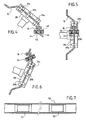
- la figure 2 est une vue schématique en élévation et avec coupe partielle, illustrant la mise en oeuvre du procédé ;
- la figure 3 est une vue schématique selon la flèche III de la figure 2 ;
- les figures 4 à 6 sont des vues semblables à la figure 3 illustrant différentes étapes du processus de trempe thermique ; et
- la figure 7 est une coupe longitudinale d'une barre tubulaire, avant cintrage.
Claims (14)
- Installation de trempe thermique pour élément métallique allongé, comme par exemple un élément de suspension de véhicule automobile, caractérisé en ce qu'il comporte :des moyens de chauffage par induction (15) comprenant une bobine d'induction (16) fixe,des moyens de manipulation (18) comprenant un premier robot multiaxe (27) portant ledit élément métallique et agencé pour faire passer ledit élément au travers de ladite bobine d'induction suivant un trajet prédéterminé, etDes moyens de refroidissement (20) agencés en aval de ladite bobine d'induction par rapport au sens de déplacement dudit élément.
- Installation selon la revendication 1, caractérisée en ce que lesdits moyens de manipulation (18) sont agencés pour déplacer ledit élément de sorte qu'une fibre neutre de celui-ci traverse ladite bobine sensiblement au centre de celle-ci.
- Installation selon la revendication 1 ou 2, caractérisée en ce que lesdits moyens de manipulation comportent, montés sur un support (28), des pinces escamotables (29a, 29b, 29c) espacées les unes des autres sur ledit support, pour tenir ledit élément pendant son passage au travers de ladite bobine.
- Installation selon la revendication 3, caractérisée en ce que ledit support porte trois pinces précitées dont l'une (29c) est montée à coulissement libre.
- Installation selon l'une des revendications précédentes, caractérisée en ce que ladite bobine d'induction (16) est sensiblement horizontale.
- Installation selon l'une des revendications prédédentes, caractérisée en ce que lesdits moyens de refroidissement comportent une douche (32) de structure annulaire, dimensionnée pour pouvoir être traversée par ledit élément, ladite douche étant agencée en aval de ladite bobine d'induction (16) et à proximité de celle-ci.
- Installation selon la revendication 6, caractérisée en ce que ladite douche (32) est portée par un second robot multi-axe (36) opérant en synchronisme avec ledit premier robot.
- Installation selon l'une des revendications 6 ou 7, caractérisée en ce que ladite douche comporte une face d'entrée (40) formant écran, muni d'un passage central au travers duquel est engagé ledit élément, et en ce que ledit passage est prolongé par une cavité d'aspersion (42) dans laquelle sont installées des buses de projection (44) de fluide de refroidissement, lesdites buses étant orientées sensiblement vers l'axe dudit passage central, en aval dudit passage central.
- Procédé de fabrication d'un élément métallique allongé, caractérisé en ce qu'il comporte une étape de trempe thermique consistant à faire passer ledit élément (12) au travers d'une bobine d'induction fixe (16) en le manipulant avec un robot multiaxe, ladite bobine faisant partie de moyens de chauffage par induction et à refroidir l'élément en aval de ladite bobine d'induction.
- Procédé de fabrication selon la revendication 9, caractérisé en ce que, ledit élément métallique allongé étant élaboré dans une barre métallique pleine, on opère une trempe superficielle pour obtenir une zone externe à structure martensitique et une zone de coeur à structure ferrito perlitique.
- Procédé selon la revendication 9, caractérisé en ce que ledit élément étant élaboré dans une barre métallique tubulaire, on réalise une trempe sur une profondeur propre à créer une structure martensitique sur la totalité de l'épaisseur de ladite barre tubulaire et on procède à un grenaillage interne de ladite barre tubulaire.
- Procédé selon la revendication 9 ou 11 caractérisé en ce qu'on élabore ledit élément dans une barre métallique tubulaire d'epaisseur constante.
- Procédé selon le revendication 9 ou 11 caractérisé en ce qu'on élabore ledit élément dans une barre métallique tubulaire d'épaisseur variable les parties le plus épaisses de ladite barre correspondant à des zones de l'élément soumises à de plus fortes contraintes.
- Procédé selon l'une des revendications 9 à 13 caractérisé en ce qu'on traite spécifiquement ou uniquement les parties de ladite barre correspondant à des zones de l'élément soumises à de plus fortes contraintes.
Applications Claiming Priority (2)
| Application Number | Priority Date | Filing Date | Title |
|---|---|---|---|
| FR0212170A FR2845397B1 (fr) | 2002-10-02 | 2002-10-02 | Installation de trempe par induction, notamment pour la fabrication d'elements de suspension |
| FR0212170 | 2002-10-02 |
Publications (2)
| Publication Number | Publication Date |
|---|---|
| EP1405926A1 true EP1405926A1 (fr) | 2004-04-07 |
| EP1405926B1 EP1405926B1 (fr) | 2007-05-30 |
Family
ID=31985396
Family Applications (1)
| Application Number | Title | Priority Date | Filing Date |
|---|---|---|---|
| EP03292430A Expired - Lifetime EP1405926B1 (fr) | 2002-10-02 | 2003-10-02 | Installation de trempe par induction, notamment pour la fabrication d'éléments de suspension |
Country Status (6)
| Country | Link |
|---|---|
| US (1) | US7368077B2 (fr) |
| EP (1) | EP1405926B1 (fr) |
| JP (1) | JP2004270025A (fr) |
| AT (1) | ATE363547T1 (fr) |
| DE (1) | DE60314069T2 (fr) |
| FR (1) | FR2845397B1 (fr) |
Cited By (2)
| Publication number | Priority date | Publication date | Assignee | Title |
|---|---|---|---|---|
| WO2016156679A1 (fr) | 2015-03-30 | 2016-10-06 | Eaton Leonard Group | Dispositif de traitement par trempe thermique d'un élément métallique, du type tube ou barre, présentant des tronçons cintrés. |
| US20220333222A1 (en) * | 2021-04-14 | 2022-10-20 | Kondex Corporation | Fatigue improved harvester component via laser shock peening |
Families Citing this family (19)
| Publication number | Priority date | Publication date | Assignee | Title |
|---|---|---|---|---|
| US8538015B2 (en) | 2007-03-28 | 2013-09-17 | Intel Corporation | Flexible architecture and instruction for advanced encryption standard (AES) |
| US20090158587A1 (en) * | 2007-12-19 | 2009-06-25 | Caterpillar Inc. | Heat-based redimensioning for remanufacture of ferrous components |
| JP5322001B2 (ja) * | 2008-05-19 | 2013-10-23 | 高周波熱錬株式会社 | 鉄鋼材料及びその製造方法並びに高周波焼入れ部品 |
| JP5496584B2 (ja) * | 2009-09-04 | 2014-05-21 | デルタ工業株式会社 | 板状部品の高周波焼入れ方法 |
| AU2011204164B2 (en) * | 2010-01-06 | 2014-01-30 | Nippon Steel Corporation | Method and apparatus for manufacturing a bent member |
| DE102010020942B4 (de) * | 2010-05-19 | 2012-05-10 | Benteler Automobiltechnik Gmbh | Spannvorrichtung und Verfahren zum Wärmebehandeln eines Langmaterials |
| DE102010054363B3 (de) * | 2010-12-13 | 2011-12-29 | Benteler Automobiltechnik Gmbh | Vorrichtung zur Wärmebehandlung von Langmaterial sowie Verfahren zum Wärmebehandeln eines Langmaterials |
| JP6071608B2 (ja) | 2012-03-09 | 2017-02-01 | 新日鐵住金ステンレス株式会社 | 耐酸化性に優れたフェライト系ステンレス鋼板 |
| DE102012106713B3 (de) * | 2012-07-24 | 2013-09-19 | Benteler Automobiltechnik Gmbh | Abkühlvorrichtung für eine Induktionsvorrichtung |
| DE102013001898A1 (de) * | 2013-02-05 | 2014-08-07 | Thermprotec Gmbh | Verfahren zum Verbessern der Temperaturverteilung beim induktiven bzw. konduktiven Härten von geformten Rohren und Stäben insbesondere aber nicht ausschließlich für den Einsatz als Fahrwerksstabilisatoren in Automobilen |
| DE102013109076B3 (de) * | 2013-08-22 | 2014-10-09 | Benteler Automobiltechnik Gmbh | Abschreckbrause für Induktionshärteeinrichtungen |
| CN104831047A (zh) * | 2015-03-23 | 2015-08-12 | 宁波霍科电器有限公司 | 一种用于轴类工件淬火的旋转升降机构 |
| WO2016194627A1 (fr) | 2015-06-01 | 2016-12-08 | 株式会社三五 | Appareil de durcissement d'élément long et procédé de durcissement d'élément long |
| DE102019129175A1 (de) * | 2019-10-29 | 2021-04-29 | Thermprotec Gmbh | Verfahren und Vorrichtung zur thermischen Behandlung eines rohrförmigen metallischen Bauteils |
| CN111270053B (zh) * | 2020-03-30 | 2021-12-24 | 上海精智实业股份有限公司 | 一种淬火系统及淬火方法 |
| CN114134297B (zh) * | 2021-12-01 | 2023-10-03 | 安庆汇通汽车部件股份有限公司 | 稳定杆多功能淬火槽及其对稳定杆进行淬回火的应用方法 |
| DE102023105277A1 (de) | 2023-03-03 | 2024-09-05 | Alcomex Beheer Bv | Fertigungsanlage zur Wärmebehandlung von warm- und kaltgeformten Federelementen, sowie ein Verfahren zur Wärmebehandlung von kaltgeformten Federelementen |
| CN119753289B (zh) * | 2025-03-04 | 2025-06-03 | 中国铁建重工集团股份有限公司 | 薄壁环件表面感应淬火设备、系统及方法 |
| CN120485496B (zh) * | 2025-07-14 | 2025-10-10 | 事必得精密机械(上海)有限公司 | 一种零部件淬火处理设备 |
Citations (6)
| Publication number | Priority date | Publication date | Assignee | Title |
|---|---|---|---|---|
| FR2160567A1 (fr) * | 1971-11-20 | 1973-06-29 | Schmidt Hochfrequenzwaerme Co | Procede et dispositif pour la trempe des barres rondes a extremites recourbees |
| JPH11269550A (ja) * | 1998-03-23 | 1999-10-05 | Honda Motor Co Ltd | シャフトスクリュの高周波焼入れ方法 |
| JPH11350024A (ja) * | 1998-06-10 | 1999-12-21 | Ysk Corporation:Kk | 焼入用軸支持装置 |
| JP2000024737A (ja) * | 1998-07-14 | 2000-01-25 | Mitsubishi Motors Corp | スタビライザバーの製造方法 |
| EP1052295A2 (fr) * | 1999-05-12 | 2000-11-15 | Benteler Ag | Méthode de fabrication d'éléments structurels dans la construction automobile |
| US6290898B1 (en) * | 1999-10-06 | 2001-09-18 | Dongwonmetal Ind. Co., Ltd. | Apparatus for heat treatment of impact beams for use in automobiles |
Family Cites Families (2)
| Publication number | Priority date | Publication date | Assignee | Title |
|---|---|---|---|---|
| US4675488A (en) * | 1986-06-25 | 1987-06-23 | Tocco, Inc. | Method for hardening gears by induction heating |
| US6018155A (en) * | 1997-10-29 | 2000-01-25 | Contour Hardening, Inc. | Induction hardening apparatus for a crankshaft |
-
2002
- 2002-10-02 FR FR0212170A patent/FR2845397B1/fr not_active Expired - Lifetime
-
2003
- 2003-10-02 DE DE60314069T patent/DE60314069T2/de not_active Expired - Lifetime
- 2003-10-02 AT AT03292430T patent/ATE363547T1/de not_active IP Right Cessation
- 2003-10-02 EP EP03292430A patent/EP1405926B1/fr not_active Expired - Lifetime
- 2003-10-02 JP JP2003344477A patent/JP2004270025A/ja active Pending
- 2003-10-02 US US10/677,185 patent/US7368077B2/en not_active Expired - Lifetime
Patent Citations (6)
| Publication number | Priority date | Publication date | Assignee | Title |
|---|---|---|---|---|
| FR2160567A1 (fr) * | 1971-11-20 | 1973-06-29 | Schmidt Hochfrequenzwaerme Co | Procede et dispositif pour la trempe des barres rondes a extremites recourbees |
| JPH11269550A (ja) * | 1998-03-23 | 1999-10-05 | Honda Motor Co Ltd | シャフトスクリュの高周波焼入れ方法 |
| JPH11350024A (ja) * | 1998-06-10 | 1999-12-21 | Ysk Corporation:Kk | 焼入用軸支持装置 |
| JP2000024737A (ja) * | 1998-07-14 | 2000-01-25 | Mitsubishi Motors Corp | スタビライザバーの製造方法 |
| EP1052295A2 (fr) * | 1999-05-12 | 2000-11-15 | Benteler Ag | Méthode de fabrication d'éléments structurels dans la construction automobile |
| US6290898B1 (en) * | 1999-10-06 | 2001-09-18 | Dongwonmetal Ind. Co., Ltd. | Apparatus for heat treatment of impact beams for use in automobiles |
Non-Patent Citations (3)
| Title |
|---|
| PATENT ABSTRACTS OF JAPAN vol. 2000, no. 01 31 January 2000 (2000-01-31) * |
| PATENT ABSTRACTS OF JAPAN vol. 2000, no. 03 30 March 2000 (2000-03-30) * |
| PATENT ABSTRACTS OF JAPAN vol. 2000, no. 04 31 August 2000 (2000-08-31) * |
Cited By (3)
| Publication number | Priority date | Publication date | Assignee | Title |
|---|---|---|---|---|
| WO2016156679A1 (fr) | 2015-03-30 | 2016-10-06 | Eaton Leonard Group | Dispositif de traitement par trempe thermique d'un élément métallique, du type tube ou barre, présentant des tronçons cintrés. |
| CN108012547A (zh) * | 2015-03-30 | 2018-05-08 | 伊顿伦纳德集团 | 具有曲线段的管状或棒状金属元件的热淬火处理设备 |
| US20220333222A1 (en) * | 2021-04-14 | 2022-10-20 | Kondex Corporation | Fatigue improved harvester component via laser shock peening |
Also Published As
| Publication number | Publication date |
|---|---|
| DE60314069D1 (de) | 2007-07-12 |
| DE60314069T2 (de) | 2008-01-31 |
| JP2004270025A (ja) | 2004-09-30 |
| US7368077B2 (en) | 2008-05-06 |
| US20040226632A1 (en) | 2004-11-18 |
| ATE363547T1 (de) | 2007-06-15 |
| EP1405926B1 (fr) | 2007-05-30 |
| FR2845397B1 (fr) | 2005-07-29 |
| FR2845397A1 (fr) | 2004-04-09 |
Similar Documents
| Publication | Publication Date | Title |
|---|---|---|
| EP1405926B1 (fr) | Installation de trempe par induction, notamment pour la fabrication d'éléments de suspension | |
| EP0326005B1 (fr) | Procédés et dispositifs permettant de traiter thermiquement des fils d'acier au carbone de façon à obtenir une structure perlitique fine | |
| CN101983247A (zh) | 钢材、钢材的制造方法及钢材的制造装置 | |
| FR2515777A1 (fr) | Structure tubulaire metallique avec une resistance amelioree a l'ecrasement, et son procede de fabrication | |
| LU81418A1 (fr) | Procede et installation de faconnage et de traitement en continu de barres d'acier | |
| US20120211126A1 (en) | Method of induction heating and quenching | |
| US20090020194A1 (en) | Method of Induction Hardening | |
| KR101295315B1 (ko) | 이중관형 엘보의 성형방법 | |
| WO2011124846A1 (fr) | Traitement d'une canne chauffante destinee a un pressuriseur du circuit primaire d'un reacteur nucleaire | |
| EP3670014A1 (fr) | Procédé de redressage d'un arbre par application d'un effort variable radial d'écrouissage sur l'arbre en rotation | |
| JP4255694B2 (ja) | 二軸スクリュー押出機のバレルを製造する方法およびその装置 | |
| JP2001152315A (ja) | 中空スタビライザと、その製造方法 | |
| KR101503054B1 (ko) | 금속볼을 이용한 이중관형 엘보의 성형방법 | |
| US7011720B2 (en) | Double-taper steel wire and continuous heat treating method and device therefor | |
| FR2810050A1 (fr) | Procede et outils de trempe de pieces ayant un trou, et vilebrequin de moteur | |
| FR2522688A1 (fr) | Procede et installation de traitement thermique de barres en acier allie pretes a l'emploi, notamment pour la construction mecanique | |
| KR20060136020A (ko) | 알루미늄 합금 파이프 및 그 제조 방법 | |
| KR20070000050A (ko) | 알루미늄 합금 파이프 및 그 제조 방법 | |
| JP2005088066A (ja) | 軸肥大加工方法 | |
| BE832391R (fr) | Procede et dispositif de patentage de fils d'acier | |
| JP3856940B2 (ja) | 熱間曲げ金属条材及びその製造方法 | |
| JPH0547317B2 (fr) | ||
| EP3623486A1 (fr) | Procédé de redressage d'un arbre métallique comportant une étape de revenu localisé | |
| CN121496294A (zh) | 一种适应于ccus-eor注入用耐蚀合金连续管及其制造方法 | |
| JPS5994521A (ja) | 金属製ト−シヨンバ−の製造方法 |
Legal Events
| Date | Code | Title | Description |
|---|---|---|---|
| PUAI | Public reference made under article 153(3) epc to a published international application that has entered the european phase |
Free format text: ORIGINAL CODE: 0009012 |
|
| AK | Designated contracting states |
Kind code of ref document: A1 Designated state(s): AT BE BG CH CY CZ DE DK EE ES FI FR GB GR HU IE IT LI LU MC NL PT RO SE SI SK TR |
|
| AX | Request for extension of the european patent |
Extension state: AL LT LV MK |
|
| 17P | Request for examination filed |
Effective date: 20041007 |
|
| AKX | Designation fees paid |
Designated state(s): AT BE BG CH CY CZ DE DK EE ES FI FR GB GR HU IE IT LI LU MC NL PT RO SE SI SK TR |
|
| 17Q | First examination report despatched |
Effective date: 20050608 |
|
| GRAP | Despatch of communication of intention to grant a patent |
Free format text: ORIGINAL CODE: EPIDOSNIGR1 |
|
| GRAS | Grant fee paid |
Free format text: ORIGINAL CODE: EPIDOSNIGR3 |
|
| GRAA | (expected) grant |
Free format text: ORIGINAL CODE: 0009210 |
|
| AK | Designated contracting states |
Kind code of ref document: B1 Designated state(s): AT BE BG CH CY CZ DE DK EE ES FI FR GB GR HU IE IT LI LU MC NL PT RO SE SI SK TR |
|
| PG25 | Lapsed in a contracting state [announced via postgrant information from national office to epo] |
Ref country code: FI Free format text: LAPSE BECAUSE OF FAILURE TO SUBMIT A TRANSLATION OF THE DESCRIPTION OR TO PAY THE FEE WITHIN THE PRESCRIBED TIME-LIMIT Effective date: 20070530 |
|
| REG | Reference to a national code |
Ref country code: GB Ref legal event code: FG4D Free format text: NOT ENGLISH |
|
| REG | Reference to a national code |
Ref country code: CH Ref legal event code: EP |
|
| REG | Reference to a national code |
Ref country code: IE Ref legal event code: FG4D Free format text: LANGUAGE OF EP DOCUMENT: FRENCH |
|
| REF | Corresponds to: |
Ref document number: 60314069 Country of ref document: DE Date of ref document: 20070712 Kind code of ref document: P |
|
| PG25 | Lapsed in a contracting state [announced via postgrant information from national office to epo] |
Ref country code: SE Free format text: LAPSE BECAUSE OF FAILURE TO SUBMIT A TRANSLATION OF THE DESCRIPTION OR TO PAY THE FEE WITHIN THE PRESCRIBED TIME-LIMIT Effective date: 20070830 |
|
| PG25 | Lapsed in a contracting state [announced via postgrant information from national office to epo] |
Ref country code: ES Free format text: LAPSE BECAUSE OF FAILURE TO SUBMIT A TRANSLATION OF THE DESCRIPTION OR TO PAY THE FEE WITHIN THE PRESCRIBED TIME-LIMIT Effective date: 20070910 |
|
| PG25 | Lapsed in a contracting state [announced via postgrant information from national office to epo] |
Ref country code: AT Free format text: LAPSE BECAUSE OF FAILURE TO SUBMIT A TRANSLATION OF THE DESCRIPTION OR TO PAY THE FEE WITHIN THE PRESCRIBED TIME-LIMIT Effective date: 20070530 |
|
| NLV1 | Nl: lapsed or annulled due to failure to fulfill the requirements of art. 29p and 29m of the patents act | ||
| GBV | Gb: ep patent (uk) treated as always having been void in accordance with gb section 77(7)/1977 [no translation filed] |
Effective date: 20070530 |
|
| REG | Reference to a national code |
Ref country code: IE Ref legal event code: FD4D |
|
| PG25 | Lapsed in a contracting state [announced via postgrant information from national office to epo] |
Ref country code: CZ Free format text: LAPSE BECAUSE OF FAILURE TO SUBMIT A TRANSLATION OF THE DESCRIPTION OR TO PAY THE FEE WITHIN THE PRESCRIBED TIME-LIMIT Effective date: 20070530 Ref country code: DK Free format text: LAPSE BECAUSE OF FAILURE TO SUBMIT A TRANSLATION OF THE DESCRIPTION OR TO PAY THE FEE WITHIN THE PRESCRIBED TIME-LIMIT Effective date: 20070530 Ref country code: PT Free format text: LAPSE BECAUSE OF FAILURE TO SUBMIT A TRANSLATION OF THE DESCRIPTION OR TO PAY THE FEE WITHIN THE PRESCRIBED TIME-LIMIT Effective date: 20071030 Ref country code: NL Free format text: LAPSE BECAUSE OF FAILURE TO SUBMIT A TRANSLATION OF THE DESCRIPTION OR TO PAY THE FEE WITHIN THE PRESCRIBED TIME-LIMIT Effective date: 20070530 Ref country code: BG Free format text: LAPSE BECAUSE OF FAILURE TO SUBMIT A TRANSLATION OF THE DESCRIPTION OR TO PAY THE FEE WITHIN THE PRESCRIBED TIME-LIMIT Effective date: 20070830 Ref country code: SI Free format text: LAPSE BECAUSE OF FAILURE TO SUBMIT A TRANSLATION OF THE DESCRIPTION OR TO PAY THE FEE WITHIN THE PRESCRIBED TIME-LIMIT Effective date: 20070530 Ref country code: IE Free format text: LAPSE BECAUSE OF FAILURE TO SUBMIT A TRANSLATION OF THE DESCRIPTION OR TO PAY THE FEE WITHIN THE PRESCRIBED TIME-LIMIT Effective date: 20070530 |
|
| PG25 | Lapsed in a contracting state [announced via postgrant information from national office to epo] |
Ref country code: SK Free format text: LAPSE BECAUSE OF FAILURE TO SUBMIT A TRANSLATION OF THE DESCRIPTION OR TO PAY THE FEE WITHIN THE PRESCRIBED TIME-LIMIT Effective date: 20070530 |
|
| PLBE | No opposition filed within time limit |
Free format text: ORIGINAL CODE: 0009261 |
|
| STAA | Information on the status of an ep patent application or granted ep patent |
Free format text: STATUS: NO OPPOSITION FILED WITHIN TIME LIMIT |
|
| BERE | Be: lapsed |
Owner name: ALLEVARD REJNA AUTOSUSPENSIONS Effective date: 20071031 |
|
| PG25 | Lapsed in a contracting state [announced via postgrant information from national office to epo] |
Ref country code: IT Free format text: LAPSE BECAUSE OF FAILURE TO SUBMIT A TRANSLATION OF THE DESCRIPTION OR TO PAY THE FEE WITHIN THE PRESCRIBED TIME-LIMIT Effective date: 20070530 Ref country code: GR Free format text: LAPSE BECAUSE OF FAILURE TO SUBMIT A TRANSLATION OF THE DESCRIPTION OR TO PAY THE FEE WITHIN THE PRESCRIBED TIME-LIMIT Effective date: 20070831 Ref country code: GB Free format text: LAPSE BECAUSE OF FAILURE TO SUBMIT A TRANSLATION OF THE DESCRIPTION OR TO PAY THE FEE WITHIN THE PRESCRIBED TIME-LIMIT Effective date: 20070530 |
|
| 26N | No opposition filed |
Effective date: 20080303 |
|
| PG25 | Lapsed in a contracting state [announced via postgrant information from national office to epo] |
Ref country code: MC Free format text: LAPSE BECAUSE OF NON-PAYMENT OF DUE FEES Effective date: 20071031 Ref country code: RO Free format text: LAPSE BECAUSE OF FAILURE TO SUBMIT A TRANSLATION OF THE DESCRIPTION OR TO PAY THE FEE WITHIN THE PRESCRIBED TIME-LIMIT Effective date: 20070530 |
|
| REG | Reference to a national code |
Ref country code: CH Ref legal event code: PL |
|
| PG25 | Lapsed in a contracting state [announced via postgrant information from national office to epo] |
Ref country code: CH Free format text: LAPSE BECAUSE OF NON-PAYMENT OF DUE FEES Effective date: 20071031 Ref country code: LI Free format text: LAPSE BECAUSE OF NON-PAYMENT OF DUE FEES Effective date: 20071031 |
|
| PG25 | Lapsed in a contracting state [announced via postgrant information from national office to epo] |
Ref country code: BE Free format text: LAPSE BECAUSE OF NON-PAYMENT OF DUE FEES Effective date: 20071031 |
|
| PG25 | Lapsed in a contracting state [announced via postgrant information from national office to epo] |
Ref country code: EE Free format text: LAPSE BECAUSE OF FAILURE TO SUBMIT A TRANSLATION OF THE DESCRIPTION OR TO PAY THE FEE WITHIN THE PRESCRIBED TIME-LIMIT Effective date: 20070530 |
|
| PG25 | Lapsed in a contracting state [announced via postgrant information from national office to epo] |
Ref country code: CY Free format text: LAPSE BECAUSE OF FAILURE TO SUBMIT A TRANSLATION OF THE DESCRIPTION OR TO PAY THE FEE WITHIN THE PRESCRIBED TIME-LIMIT Effective date: 20070530 |
|
| PG25 | Lapsed in a contracting state [announced via postgrant information from national office to epo] |
Ref country code: LU Free format text: LAPSE BECAUSE OF NON-PAYMENT OF DUE FEES Effective date: 20071002 |
|
| PG25 | Lapsed in a contracting state [announced via postgrant information from national office to epo] |
Ref country code: HU Free format text: LAPSE BECAUSE OF FAILURE TO SUBMIT A TRANSLATION OF THE DESCRIPTION OR TO PAY THE FEE WITHIN THE PRESCRIBED TIME-LIMIT Effective date: 20071201 Ref country code: TR Free format text: LAPSE BECAUSE OF FAILURE TO SUBMIT A TRANSLATION OF THE DESCRIPTION OR TO PAY THE FEE WITHIN THE PRESCRIBED TIME-LIMIT Effective date: 20070530 |
|
| REG | Reference to a national code |
Ref country code: FR Ref legal event code: PLFP Year of fee payment: 13 |
|
| REG | Reference to a national code |
Ref country code: FR Ref legal event code: PLFP Year of fee payment: 14 |
|
| REG | Reference to a national code |
Ref country code: FR Ref legal event code: PLFP Year of fee payment: 15 |
|
| REG | Reference to a national code |
Ref country code: FR Ref legal event code: PLFP Year of fee payment: 16 |
|
| PGFP | Annual fee paid to national office [announced via postgrant information from national office to epo] |
Ref country code: DE Payment date: 20211008 Year of fee payment: 19 |
|
| PGFP | Annual fee paid to national office [announced via postgrant information from national office to epo] |
Ref country code: FR Payment date: 20211022 Year of fee payment: 19 |
|
| REG | Reference to a national code |
Ref country code: DE Ref legal event code: R082 Ref document number: 60314069 Country of ref document: DE Representative=s name: CBDL PATENTANWAELTE GBR, DE |
|
| REG | Reference to a national code |
Ref country code: DE Ref legal event code: R119 Ref document number: 60314069 Country of ref document: DE |
|
| PG25 | Lapsed in a contracting state [announced via postgrant information from national office to epo] |
Ref country code: FR Free format text: LAPSE BECAUSE OF NON-PAYMENT OF DUE FEES Effective date: 20221031 Ref country code: DE Free format text: LAPSE BECAUSE OF NON-PAYMENT OF DUE FEES Effective date: 20230503 |