EP1405957B1 - Verdeckte Konsoleverbindung - Google Patents
Verdeckte Konsoleverbindung Download PDFInfo
- Publication number
- EP1405957B1 EP1405957B1 EP02079104A EP02079104A EP1405957B1 EP 1405957 B1 EP1405957 B1 EP 1405957B1 EP 02079104 A EP02079104 A EP 02079104A EP 02079104 A EP02079104 A EP 02079104A EP 1405957 B1 EP1405957 B1 EP 1405957B1
- Authority
- EP
- European Patent Office
- Prior art keywords
- joint
- adapter
- stop
- fitted
- console
- Prior art date
- Legal status (The legal status is an assumption and is not a legal conclusion. Google has not performed a legal analysis and makes no representation as to the accuracy of the status listed.)
- Expired - Lifetime
Links
Images



Classifications
-
- E—FIXED CONSTRUCTIONS
- E04—BUILDING
- E04B—GENERAL BUILDING CONSTRUCTIONS; WALLS, e.g. PARTITIONS; ROOFS; FLOORS; CEILINGS; INSULATION OR OTHER PROTECTION OF BUILDINGS
- E04B1/00—Constructions in general; Structures which are not restricted either to walls, e.g. partitions, or floors or ceilings or roofs
- E04B1/18—Structures comprising elongated load-supporting parts, e.g. columns, girders, skeletons
- E04B1/20—Structures comprising elongated load-supporting parts, e.g. columns, girders, skeletons the supporting parts consisting of concrete, e.g. reinforced concrete, or other stonelike material
- E04B1/21—Connections specially adapted therefor
- E04B1/215—Connections specially adapted therefor comprising metallic plates or parts
Definitions
- the present invention relates to a concealed console joint, which is used in the joints between vertical and horizontal framework elements of a building, especially in the joints of a prefabricated concrete framework of a building, where a horizontal framework element, such as a prefabricated concrete beam, is joined and fastened to a vertical framework element, such as a prefabricated concrete column, via a load transmitting joint.
- the concealed console joint can also be used on the same principles in the beam-column joints of e.g. a reinforced-concrete composite-construction framework.
- prefabricated beams and columns are used.
- the beams are generally concrete elements of a length corresponding to only one bay between columns.
- the columns are in most cases prefabricated concrete elements of a height corresponding to several floors.
- These framework elements are joined together on the building site during installation by first erecting the prefabricated columns and then mounting a prefabricated beam between the columns.
- the prefabricated beams are connected to the prefabricated columns via cast concrete brackets, which are formed in the columns already at casting time. The beam is mounted and fastened onto this bracket provided in the column. This method is expensive and difficult as it requires complex mould equipment for the prefabrication of the column.
- bracket under the beam remains exposed, unless a lowered ceiling is built under a concrete slab.
- This bracket of the column requires a large space, typically 300 - 600 mm, which has to be taken into account when selecting the floor height of the building. Therefore, this is often an architectural question.
- parts protruding from the mould involve fairly high costs.
- FI-specification 83358 in which the prefabricated column comprises a metallic console element and the prefabricated beam has a corresponding attaching part.
- the attaching part consists of a metallic fastening slot provided at the end of the beam, the bottom and lateral surfaces of the slot being fitted against and supported by the console element in the column to receive the moment produced by the weight of the beam and an eccentric load.
- the console element is fastened with screws to a plate embedded in the cast column.
- WO 02/33185 also discloses a concealed console solution wherein a console element is fastened with screws to a plate embedded in the column.
- WO-A- 88/08061 discloses a bearing means intended for bearing coaction between a supporting structural component and a supported structural component, said means being adapted for casting into one of said structural components and for coaction with a bearing member.
- the bearing means comprises at least one substantially U-shaped section, the base of which provides the bearing surface against the bearing member, and the legs of which constitute fastening means for anchoring means and stiffeners, which transmit bearing force to the concrete surrounding the bearing means and to adjacent reinforcement.
- a supporting structural component may be a column, wall or beam, while a supported structural component may be some form of beam, often a facade element, or a so-called "windowback".
- a bearing member of the kind intended here is often a steel flat with its face vertical, a so-called knife-edge bearing.
- a knife-edge bearing of a type in WO-A- 88/08061 is a steel flat with its face vertical which is cast into and anchored in a column. The flat is disposed to project at right angles from the sides of the column and is used as a bearing bracket for beams with so-called hidden bearings.
- the structure in WO-A- 88/08061 has an elongated cast-in U-shaped steel channel, which forms an open slot in the beam end, the slot being defined by the legs and base of the U-section, the bottom surface of the base being the bearing surface of the supported element against an flat steel bracket, there also being shown a plate end stiffener.
- the bearing force to the concrete can also be transmitted with outwardly folded flange parts having flaps which have been folded up 90° from the inner ends of the flanges and are welded by welds to the legs.
- Eccentric loads in WO-A- 88/08061 have been carried by an external structure, like a horizontal hole and a bolt at the upper end of a supported beam in Fig. 10 .
- a similar elongated channel for the knife-edge bearing plate is also arranged in the supporting column.
- GB-A-2179115 discloses a construction system consists of a beam fixed to the side face of a concrete column with the aid of a carrying member.
- the carrying member has three vertical abutment faces engaged against the side plate of the column and a horizontal carrying surface for the beam above the lower margin of the abutment face.
- the vertical abutment faces are provided with three hooks extending upward and projecting towards the concrete column.
- the side plate of the concrete column is provided with three recesses extending upward into which the hooks of the carrying member are inserted.
- the object of the present invention is to achieve a new type of concealed console joint.
- the concealed console joint of the invention consists of three prefabricated steel parts, by means of which a joint between a prefabricated beam and a prefabricated column can be formed after the casting of the prefabricated concrete elements.
- a steel part is mounted in the mould for the prefabricated column and embedded in the column in connection with the casting of the latter.
- This steel joint element embedded in the column does not protrude at all from the surface of the column.
- the joint element of the column is provided with an opening, in which a joint adapter is mounted.
- the end of the prefabricated beam is provided with another joint element of a corresponding type, which is mounted in the mould of the prefabricated beam and embedded in the beam in connection with the casting of the beam. This joint element again has no parts protruding from the beam.
- the joint element of the beam also has an opening into which the joint adapter connecting the beam and the column becomes fastened.
- the actual joint between the prefabricated beam and the prefabricated column is formed on the construction site at installation time by using a third part, a joint adapter connecting the joints.
- This joint adapter is a discrete part and it is so shaped that it fits into the openings in the joint elements of the beam and the column.
- the joint adapter connecting the joints is mounted in the joint element of the prefabricated column before the prefabricated beam is mounted, and it is locked in place without any screws or similar fastening elements.
- the beam is so mounted that it remains supported by the adapter connecting the joints, whereupon the joint is ready to carry a load.
- the invention relates to a concealed console joint for joints between vertical and horizontal framework elements of a building, especially for joints of a prefabricated concrete framework of a building as defined by claim 1.
- the concealed console joint of the invention must also be adjustable so as to allow the variation in dimensions occurring in the manufacture and installation of the prefabricated elements to be eliminated when the console joint is being made. Adjustability of the joint is a basic requirement that has to be fulfilled to allow the installation of a large prefabricated-element framework to be accomplished without difficulties and accurately observing the designed dimensions. Variations in dimensions in the building framework appear at the end of the beam as displacements in the directions of the three principal coordinate axes and as a twisting of the column and the beam relative to their longitudinal axes. It is necessary to have a possibility of adjusting the concealed console joint at installation time in the directions of these three deviations in dimensions and relative to three twisting directions.
- the console joint is adjusted by using the following solutions: A displacement in the direction of the longitudinal axis of the beam is adjusted by utilizing the clearance provided between the beam part and the adapter part. A horizontal displacement of the beam end is adjusted by means of shims of different thicknesses placed inside the joint element and used to move the beam sideways in a horizontal direction. A twist about the longitudinal axis of the beam is adjusted by means of wedging parts, which are used to lock the joint finally in place. A vertical displacement of the beam end is adjusted by means of the joint elements, which are mounted over the joint adapter.
- the joint is required to be adjustable, the joint must also be capable of transmitting forces in all three directions of adjustment. This is achieved by locking all degrees of freedom of displacements and twists of the joint after the adjustment.
- the console joint in the ultimate application situation functions as an elbow joint for vertical loads imposed on the beam, the beam end must be allowed to turn in the vertical direction even after the joint has been cast with concrete.
- Figures 1, 2, 3 and 3A illustrate a joint element of the concealed console joint of the invention, which is placed in the column mould and embedded in the column at casting time.
- the joint element consists of the following components: Component 1 is the base plate of the column joint element and it consists of two plates joined together in a substantially square shape, the upper one of said plates being provided with a rectangular opening 1 a, the lug 22 of the beam joint element ( Fig. 7 ) being fitted into this opening 1 a.
- Components 2 are straight corrugated steel bars used as anchorages for transmitting forces to the column. Typically, 1 - 3 bars are used.
- Component 2 meets component 1.
- Component 3 is a protective casing protecting the joint.
- Component 4 consists of a rectangular steel plate, which is attached to components 1, 3 and 5 and which has a rectangular opening 6 cleft in its middle part, joint element 21 ( Fig. 7 ) being fitted into this opening.
- Component 5 forms the top of the encasement space 3a. It is a rectangular plate with a rectangular opening 9 and a collar 10, which engage the shoulder 23 ( Fig. 7 ) of the joint adapter connecting the joints is supported.
- Figures 4 - 6 present a joint element designed to be mounted in the mould of a prefabricated beam for a concealed console joint according to the invention and embedded in the prefabricated beam at casting time, said joint element consisting of the following components:
- Component 41 is a rectangular form-cut joint end plate, which is placed level with the end of the prefabricated beam.
- In the central part of component 41 there is a rectangular, downwardly open slot 42, the upper edge of the slot being provided with a stop element 43, which is supported on the upper surface 24 of the joint adapter ( Fig. 7 ).
- Component 40 is a support plate at the upper edge of component 41.
- Component 44 is a plate-like encasement forming a downwardly open space 44a.
- Components 45 and 46 are straight corrugated bars, which are anchored to joint elements 47 and 48.
- Component 47 is a lower support plate of the joint, surrounding the open space 44a.
- Component 48 is an upper support plate of the joint and it is provided with an open rectangular aperture 49.
- the encasement 44 has stop faces 20, on which the support blocks 26 ( Fig. 8 ) of the joint adapter are supported.
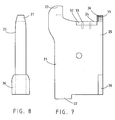
- Figures 7 and 8 present a joint adapter connecting the column and beam parts of the concealed console joint of the invention.
- the adapter body 21 is a shaped plate-like part that is adapted to fit into the opening 6 and slot 42 of the two counterparts.
- the adapter body 21 comprises a projecting part 22 which engages stop element 1a of the column and a projecting part 23 that engages stop element 10 of the column.
- the adapter body 21 has an elbow 24 on which component 43 rests.
- the adapter body comprises a shaped plate-like support block 26, which rests on the stop faces 20 of the beam part.
- the adapter body 21 comprises a rectangular part 32 which is fastened via components 33 to the adapter body 21.
- the adapter body 21 comprises a clutch element 31 having rounded edges on both sides.
- the clutch element 31 engages plate 40 of the beam.
- the front surface of the clutch element 31 is provided with a surfacing 36 made of a soft and compressible material, designed to permit a twist of the joint in the final application situation.
- the surfaces 25 of the adapter body are coated with a material preventing adhesion of concrete on the surfaces.
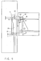
- Fig. 9 illustrates a situation where a console joint is being installed.
- the joint adapter is mounted inside the column part so that stop face 22 of the joint adapter engages stop faces 1 and 1 a of the column part, and the shoulder 23 of the adapter is fitted into the opening 9 of component 5 and shoulder 23 engages collar 10.
- the prefabricated beam is mounted by lowering it from above directly down so that the adapter body 21 enters into the slot 42 of component 41.
- the plate-like elements 27 are placed against stop faces 20 inside the encasement 44 of the beam part.
- the thickness and position of the plates 27 can be varied depending on the required lateral adjustment of the joint.
- the wedge-shaped parts 28 are placed inside the encasement 44 of the beam part, and they engage the adjusting elements 27 and the support plate 25 and 31 of the joint adapter. Horizontal displacement of the joint and longitudinal displacement of the beam are adjusted by means of joint elements 27 and 28.
- Fire protection of the joint is implemented by mounting, by the aid of joint element 35, a shaped element 34 made of fire-resistant material into the downwardly open encasement 42 of the beam part. Fire protection can also be achieved by casting the encasement 42 of the beam part full of concrete.
- surfaces 25 of the joint adapter 21 are treated with a material preventing the adhesion of concrete, and the front surface of the clutch 31 is provided with a surfacing 36 made of elastic material. The coating 25 and the material 36 permit a twist of the joint relative to the vertical axis.
- the column may also have a circular cross-section, in which case the corresponding parts of the concealed console joint are adapted to the shape of the column and the shape of the various parts of the console are therefore not restricted to the shapes described above.
Landscapes
- Engineering & Computer Science (AREA)
- Architecture (AREA)
- Physics & Mathematics (AREA)
- Electromagnetism (AREA)
- Civil Engineering (AREA)
- Structural Engineering (AREA)
- Joining Of Building Structures In Genera (AREA)
- Fittings On The Vehicle Exterior For Carrying Loads, And Devices For Holding Or Mounting Articles (AREA)
- Vehicle Step Arrangements And Article Storage (AREA)
- Forms Removed On Construction Sites Or Auxiliary Members Thereof (AREA)
- Lasers (AREA)
- Navigation (AREA)
- Connection Of Plates (AREA)
Claims (6)
- Unterputz-Auslegerverbindung für Verbindungen zwischen vertikalen und horizontalen Rahmenelementen von einem Gebäude, insbesondere für Verbindungen von einem vorfabrizierten Betonrahmen von einem Gebäude, wobei ein horizontales Rahmenelement, wie beispielsweise ein vorfabrizierter Betonträger, an einem vertikalen Rahmenelement, wie beispielsweise eine vorfabrizierte Betonsäule, über eine Lastübertragungsverbindung verbunden und befestigt ist,
wobei die Verbindung ein erstes und ein zweites Verbindungselement enthält, wobei das erste Verbindungselement in dem vertikalen Rahmenelement, wie beispielsweise eine vorfabrizierte Säule, eingefügt ist, während das zweite Verbindungselement in dem horizontalen Rahmenelement, wie beispielsweise ein vorfabrizierter Träger, eingefügt ist,
wobei die Auslegerverbindung einen Verbindungsadapter (21) enthält, mittels dessen eine Verbindung ausgebildet werden kann, indem das erste und das zweite Verbindungselement über den zuvor genannten Adapter, insbesondere ohne jegliche Teile, welche von dem horizontalen Rahmenelement vorragen, verbunden werden,
wobei das zweite Verbindungselement einen nach unten geöffneten Schlitz (42) enthält, durch welchen ein vorragendes Teil (31) von dem Verbindungsadapter in das zweite Verbindungselement eingefügt werden kann,
wobei der Verbindungsadapter (21), welcher die Verbindung verbindet, mit einer Anschlagstückfläche (24) oder mit Anschlagstückflächen bereitgestellt ist, während das zweite Verbindungselement ein Anschlagstückelement (43) oder Elemente enthält, an welche die Verbindungsadapter-Anschlagstückfläche (24) eingefügt werden kann,
wobei der Verbindungsadapter (21), welcher die Verbindung an dem Ende von dem ersten Verbindungselement verbindet, ebenfalls einen im Wesentlichen vorragenden Aufbau hat, und das erste Verbindungselement mit einer Öffnung (6) bereitgestellt ist, durch welche das Ende von dem Verbindungsadapter in das erste Verbindungselement eingefügt werden kann, wobei der Adapter derart entworfen ist, dass er ohne jegliche spezielle Befestigungselemente in das erste Verbindungselement eingefügt wird,
dadurch gekennzeichnet, dass
das erste Verbindungselement eine untere horizontale Basisplatte (1), welche aus zwei im Wesentlichen quadratischen Plattenteilen, einem oberen Plattenteil und einem unteren Plattenteil ausgebildet ist, und ein oberes horizontales Bauteil (5), welches eine obere Platte ausbildet, hat, wobei die Basisplatte (1) und die obere Platte zusammen mit den Bauteilen (3) und (4) einen kastenförmigen Raum (3a) ausbilden,
der Verbindungsadapter ein erstes unteres nach unten vorragendes Anschlagstückelement (22), welches ein Anschlussstück ist, und ein zweites nach oben vorragendes Anschlagstückelement (23), welches eine Schulter ist, enthält, wobei die Anschlagstückelemente in den kastenförmigen Raum (3a) von dem ersten Verbindungselement einzusetzen sind, und das erste Verbindungselement ein entsprechendes erstes Basisplatten-Anschlagstückelement und ein zweites Oberplatten-Anschlagstückelement in der Form von Öffnungen oder Hohlräumen und Anschlagstückflächen in der Basisplatte (1) und der Oberplatte hat, wobei das erste Basisplatten-Anschlagstückelement durch eine rechteckige Öffnung (1a) in dem oberen Plattenteil von der unteren Basisplatte (1) ausgebildet ist, wobei das zweite Basisplatten-Anschlagstückelement durch eine rechteckige Öffnung (9) in dem oberen Oberplattenteil ausgebildet ist,
so dass das erste untere nach unten vorragende Anschlagstückelement (22) von dem Verbindungsadapter (21) in das erste Basisplatten-Anschlagstückelement von dem ersten Verbindungselement eingefügt werden kann, und das zweite nach oben vorragende Anschlagstückelement (23) von dem Verbindungsadapter (21) in das zweite Oberplatten-Anschlagstückelement von dem ersten Verbindungselement eingefügt werden kann,
das zweite nach oben vorragende Anschlagstückelement (23) von dem Verbindungsadapter (21) eine Anschlagstückfläche von dem zweiten Oberplatten-Anschlagstückelement von dem ersten Verbindungselement in Eingriff nimmt, während das erste untere nach unten vorragende Anschlagstückelement (22) von dem Verbindungsadapter (21) gleichzeitig eine Anschlagstückfläche in Eingriff nimmt, welche in der Öffnung (1a) von der ersten Basisplatte (1) von dem ersten Verbindungselement enthalten ist, und
das zweite Verbindungselement einen nach unten geöffneten Raum (44a) hat, welcher mit einer Endplatte (41) mit dem nach unten geöffneten Schlitz (42) bereitgestellt ist, wobei die obere Kante von dem Schlitz, welcher mit einem Anschlagstückelement (43) bereitgestellt ist, dazu ausgelegt ist, auf der oberen Oberfläche (24) von dem Verbindungsadapter gelagert zu sein, so dass der Träger befestigt werden kann, indem er von oberhalb direkt nach unten abgesenkt wird, so dass der Verbindungsadapter (21) in den Schlitz (42) eintritt, und dass
es einen einstellbaren Steigblock (32) enthält, mittels dessen der vertikale Spielraum von der Verbindung eingestellt werden kann, indem die Höhe von der Oberfläche (24) von dem Verbindungsadapter variiert wird. - Unterputz-Auslegerverbindung nach Anspruch 1, dadurch gekennzeichnet, dass der Verbindungsadapter (21) ein vorragendes Teil (31) enthält, welches eine rechteckige Form und abgerundete Kanten an zwei Seiten hat, und die Vorderfläche von dem vorragenden Teil, welche gegen das zweite Verbindungselement (40) platziert ist, mit einer Füllung (36) bereitgestellt ist, welche aus einem elastischen oder nachgiebigen Material erstellt ist.
- Unterputz-Auslegerverbindung nach Anspruch 1, dadurch gekennzeichnet, dass sie Einstellelemente (27, 28) von einer rechteckigen oder keilförmigen Form und von unterschiedlichen Dicken enthält, wobei die Elemente dazu verwendet werden, um den lateralen Spielraum einzustellen, und welche zwischen den Anschlagstückflächen (20, 25) platziert werden können.
- Unterputz-Auslegerverbindung nach Anspruch 1, dadurch gekennzeichnet, dass der Anschlagstückblock (26) von dem Verbindungsadapter (21) fest gegen die Anschlagstückflächen (20) von dem zweiten Verbindungselement gepresst ist.
- Unterputz-Auslegerverbindung nach Anspruch 1, dadurch gekennzeichnet, dass das vorragende Teil (22) von dem Verbindungsadapter (21) auf einer Platte (1) von dem ersten Verbindungselement und auf einer Stange (2), welche unterhalb davon platziert ist, ruht.
- Unterputz-Auslegerverbindung nach Anspruch 1, dadurch gekennzeichnet, dass die nach unten geöffnete Verkleidung (44a), welche in dem zweiten Verbindungselement enthalten ist, im Wesentlichen vollständig mit Beton gegossen ist, und dass die Materialien von der vorderen Oberfläche (36) und den seitlichen Oberflächen (25) von dem vorragenden Teil (31) von dem Verbindungsadapter (21) ein Verwinden von der Verbindung in Relation zu der vertikalen Achse nach dem Gießen erlauben.
Priority Applications (8)
| Application Number | Priority Date | Filing Date | Title |
|---|---|---|---|
| ES02079104T ES2319261T3 (es) | 2002-10-03 | 2002-10-03 | Junta del tipo de consola oculta. |
| AT02079104T ATE416280T1 (de) | 2002-10-03 | 2002-10-03 | Verdeckte konsoleverbindung |
| DK02079104T DK1405957T3 (da) | 2002-10-03 | 2002-10-03 | Skjult konsolforbindelse |
| PT02079104T PT1405957E (pt) | 2002-10-03 | 2002-10-03 | Junta de consola oculta |
| DE60230144T DE60230144D1 (de) | 2002-10-03 | 2002-10-03 | Verdeckte Konsoleverbindung |
| EP02079104A EP1405957B1 (de) | 2002-10-03 | 2002-10-03 | Verdeckte Konsoleverbindung |
| MYPI20031298A MY135622A (en) | 2002-10-03 | 2003-04-08 | Concealed console joint |
| CY20091100232T CY1109958T1 (el) | 2002-10-03 | 2009-02-27 | Κρυμενη ενωση κονσολας |
Applications Claiming Priority (1)
| Application Number | Priority Date | Filing Date | Title |
|---|---|---|---|
| EP02079104A EP1405957B1 (de) | 2002-10-03 | 2002-10-03 | Verdeckte Konsoleverbindung |
Publications (2)
| Publication Number | Publication Date |
|---|---|
| EP1405957A1 EP1405957A1 (de) | 2004-04-07 |
| EP1405957B1 true EP1405957B1 (de) | 2008-12-03 |
Family
ID=31985109
Family Applications (1)
| Application Number | Title | Priority Date | Filing Date |
|---|---|---|---|
| EP02079104A Expired - Lifetime EP1405957B1 (de) | 2002-10-03 | 2002-10-03 | Verdeckte Konsoleverbindung |
Country Status (8)
| Country | Link |
|---|---|
| EP (1) | EP1405957B1 (de) |
| AT (1) | ATE416280T1 (de) |
| CY (1) | CY1109958T1 (de) |
| DE (1) | DE60230144D1 (de) |
| DK (1) | DK1405957T3 (de) |
| ES (1) | ES2319261T3 (de) |
| MY (1) | MY135622A (de) |
| PT (1) | PT1405957E (de) |
Cited By (1)
| Publication number | Priority date | Publication date | Assignee | Title |
|---|---|---|---|---|
| KR102894324B1 (ko) * | 2025-02-06 | 2025-12-03 | (주)삼일씨엔에스 | 프리캐스트 콘크리트 부재 접합용 은폐형 브래킷 |
Families Citing this family (15)
| Publication number | Priority date | Publication date | Assignee | Title |
|---|---|---|---|---|
| NO321443B1 (no) * | 2004-06-30 | 2006-05-08 | Sb Produksjon As | Sammenforingssystem, enkeltelementer og fremgangsmate for bruk av dette |
| CZ2013460A3 (cs) * | 2013-06-17 | 2015-04-01 | ÄŚeskĂ© vysokĂ© uÄŤenĂ technickĂ© v Praze, Fakulta stavebnĂ, Katedra konstrukcĂ pozemnĂch staveb | Spojovací moduly u stavebních konstrukcí |
| CZ305454B6 (cs) * | 2013-06-17 | 2015-09-23 | ÄŚeskĂ© vysokĂ© uÄŤenĂ technickĂ© v Praze, Fakulta stavebnĂ, Katedra konstrukcĂ pozemnĂch staveb | Spojovací modul stavebních konstrukcí |
| FI126440B (fi) * | 2014-11-13 | 2016-12-15 | Anstar Oy | Pilarikenkä |
| DE102015115564A1 (de) * | 2015-09-15 | 2017-03-16 | Bam Deutschland Ag | Podestlagersystem, Podestsystem, Konsole |
| JP6775327B2 (ja) * | 2016-05-16 | 2020-10-28 | 株式会社竹中工務店 | 柱仕口部の構造 |
| AT519876B1 (de) * | 2017-09-20 | 2018-11-15 | Alfred Redlberger | Vorrichtung zum kraftübertragenden Verbinden zweier Bauteile |
| CZ2017712A3 (cs) * | 2017-11-06 | 2019-04-24 | ÄŚeskĂ© vysokĂ© uÄŤenĂ technickĂ© v Praze | Demontovatelný styk prefabrikovaného průvlaku a prefabrikovaného sloupu |
| IT201800021541A1 (it) * | 2018-12-31 | 2019-03-31 | Bressaglia Pierangela | Mezzo di ancoraggio perfezionato per un sistema di ancoraggio regolabile di pareti prefabbricate alla struttura portante di un edificio |
| FI130308B (fi) * | 2021-03-11 | 2023-06-13 | Anstar Oy | Liitosjärjestely |
| FI130114B (fi) * | 2021-03-11 | 2023-03-03 | Anstar Oy | Liitosjärjestely |
| CN115233812B (zh) * | 2022-07-05 | 2023-12-05 | 上海港城建筑安装工程有限公司 | 一种预制梁与预制板的节点及其施工方法 |
| EP4459059A1 (de) * | 2023-05-03 | 2024-11-06 | Peikko Group Oy | Stahlträger und stützanordnung |
| CN116815923B (zh) * | 2023-07-31 | 2024-06-11 | 隆恩建设工程有限公司 | 一种装配式钢筋混凝土梁柱节点连接装置 |
| DE102024101963A1 (de) * | 2024-01-24 | 2025-07-24 | Pfeifer Holding Gmbh & Co. Kg | Verbindungssystem für tragelemente |
Family Cites Families (4)
| Publication number | Priority date | Publication date | Assignee | Title |
|---|---|---|---|---|
| FI72369C (fi) * | 1985-08-12 | 1987-05-11 | Partek Ab | Byggnadssystem. |
| CA1303379C (en) * | 1987-04-07 | 1992-06-16 | Bjorn O. Thoresen | Building construction |
| SE457221B (sv) * | 1987-04-10 | 1988-12-05 | Straengbetong Ab | Upplagsdon foer uppslagssamverkan mellan en baerande konstruktionsdel och en buren konstruktionsdel |
| FI20002303L (fi) | 2000-10-18 | 2002-04-19 | Teraespeikko Oy | Konsoli rakenneosan, kuten betonielementtipalkin, tukemiseksi betonipilariin tai vastaavaan rakennuksen tukirakenteeseen |
-
2002
- 2002-10-03 DK DK02079104T patent/DK1405957T3/da active
- 2002-10-03 DE DE60230144T patent/DE60230144D1/de not_active Expired - Lifetime
- 2002-10-03 AT AT02079104T patent/ATE416280T1/de active
- 2002-10-03 PT PT02079104T patent/PT1405957E/pt unknown
- 2002-10-03 ES ES02079104T patent/ES2319261T3/es not_active Expired - Lifetime
- 2002-10-03 EP EP02079104A patent/EP1405957B1/de not_active Expired - Lifetime
-
2003
- 2003-04-08 MY MYPI20031298A patent/MY135622A/en unknown
-
2009
- 2009-02-27 CY CY20091100232T patent/CY1109958T1/el unknown
Cited By (1)
| Publication number | Priority date | Publication date | Assignee | Title |
|---|---|---|---|---|
| KR102894324B1 (ko) * | 2025-02-06 | 2025-12-03 | (주)삼일씨엔에스 | 프리캐스트 콘크리트 부재 접합용 은폐형 브래킷 |
Also Published As
| Publication number | Publication date |
|---|---|
| ES2319261T3 (es) | 2009-05-06 |
| CY1109958T1 (el) | 2014-09-10 |
| MY135622A (en) | 2008-05-30 |
| EP1405957A1 (de) | 2004-04-07 |
| DE60230144D1 (de) | 2009-01-15 |
| ATE416280T1 (de) | 2008-12-15 |
| PT1405957E (pt) | 2009-03-11 |
| DK1405957T3 (da) | 2009-04-06 |
Similar Documents
| Publication | Publication Date | Title |
|---|---|---|
| US6151858A (en) | Building construction system | |
| EP1405957A1 (de) | Verdeckte Konsoleverbindung | |
| CA2358747C (en) | Ring beam/lintel system | |
| US6598361B2 (en) | Mullion splice joint design | |
| CA2051393C (en) | A fire-resistant prefabricated steel beam | |
| NZ575214A (en) | Reinforced masonry panel structures with infill | |
| JP4318397B2 (ja) | 建築構造の建設に使用する建築パネル | |
| KR100626543B1 (ko) | 프리캐스트 콘크리트 보와 철골보의 합성구조 및, 철골보접합용 브라켓이 구비된 프리캐스트 콘크리트 보 | |
| JP2005105549A (ja) | プレキャストコンクリート立上げ壁の取付構造 | |
| JP2001248331A (ja) | 制震ダンパーの設置構造および設置方法 | |
| RU2360077C2 (ru) | Скрытое консольное соединение | |
| JP3153210B2 (ja) | コンクリート構造物の上床版補強方法 | |
| JP2001164684A (ja) | プレキャストコンクリートカーテンウォールの取付方法 | |
| KR102930339B1 (ko) | 분리형 코어가 구비된 건축 시스템 | |
| JP2007169953A (ja) | プレキャストバルコニー構造体及びバルコニーを備えた鉄筋コンクリート造外断熱壁構造 | |
| JP3437925B2 (ja) | 屋根スラブの吹き上げ防止構造 | |
| SE2250286A1 (en) | System and method for suspending a framework structure on a load bearing structure of a building and use of such suspension system | |
| JP3430488B2 (ja) | 階層建物の床版施工方法 | |
| JPH02101251A (ja) | Alc建築の壁装材取付法 | |
| CA2380548A1 (en) | Thermally broken precast concrete support system for masonry veneer in building construction | |
| JP3340963B2 (ja) | 外壁と床材間の閉塞工法 | |
| JP2540314B2 (ja) | 鉄骨鉄筋コンクリ−トの柱および梁 | |
| JPS5931627B2 (ja) | 増築工法 | |
| JP2006144405A (ja) | 外壁パネルの施工方法及び外壁パネルの取付構造 | |
| JPS6355577B2 (de) |
Legal Events
| Date | Code | Title | Description |
|---|---|---|---|
| PUAI | Public reference made under article 153(3) epc to a published international application that has entered the european phase |
Free format text: ORIGINAL CODE: 0009012 |
|
| AK | Designated contracting states |
Kind code of ref document: A1 Designated state(s): AT BE BG CH CY CZ DE DK EE ES FI FR GB GR IE IT LI LU MC NL PT SE SK TR |
|
| AX | Request for extension of the european patent |
Extension state: AL LT LV MK RO SI |
|
| 17P | Request for examination filed |
Effective date: 20040903 |
|
| AKX | Designation fees paid |
Designated state(s): AT BE BG CH CY CZ DE DK EE ES FI FR GB GR IE IT LI LU MC NL PT SE SK TR |
|
| 17Q | First examination report despatched |
Effective date: 20041216 |
|
| 17Q | First examination report despatched |
Effective date: 20041216 |
|
| GRAP | Despatch of communication of intention to grant a patent |
Free format text: ORIGINAL CODE: EPIDOSNIGR1 |
|
| GRAS | Grant fee paid |
Free format text: ORIGINAL CODE: EPIDOSNIGR3 |
|
| GRAA | (expected) grant |
Free format text: ORIGINAL CODE: 0009210 |
|
| AK | Designated contracting states |
Kind code of ref document: B1 Designated state(s): AT BE BG CH CY CZ DE DK EE ES FI FR GB GR IE IT LI LU MC NL PT SE SK TR |
|
| REG | Reference to a national code |
Ref country code: GB Ref legal event code: FG4D |
|
| REG | Reference to a national code |
Ref country code: CH Ref legal event code: EP |
|
| REG | Reference to a national code |
Ref country code: IE Ref legal event code: FG4D |
|
| REF | Corresponds to: |
Ref document number: 60230144 Country of ref document: DE Date of ref document: 20090115 Kind code of ref document: P |
|
| REG | Reference to a national code |
Ref country code: PT Ref legal event code: SC4A Free format text: AVAILABILITY OF NATIONAL TRANSLATION Effective date: 20090303 |
|
| REG | Reference to a national code |
Ref country code: CH Ref legal event code: NV Representative=s name: KIRKER & CIE S.A. |
|
| REG | Reference to a national code |
Ref country code: SE Ref legal event code: TRGR |
|
| REG | Reference to a national code |
Ref country code: DK Ref legal event code: T3 |
|
| REG | Reference to a national code |
Ref country code: GR Ref legal event code: EP Ref document number: 20090400655 Country of ref document: GR |
|
| REG | Reference to a national code |
Ref country code: ES Ref legal event code: FG2A Ref document number: 2319261 Country of ref document: ES Kind code of ref document: T3 |
|
| PG25 | Lapsed in a contracting state [announced via postgrant information from national office to epo] |
Ref country code: BE Free format text: LAPSE BECAUSE OF FAILURE TO SUBMIT A TRANSLATION OF THE DESCRIPTION OR TO PAY THE FEE WITHIN THE PRESCRIBED TIME-LIMIT Effective date: 20081203 Ref country code: BG Free format text: LAPSE BECAUSE OF FAILURE TO SUBMIT A TRANSLATION OF THE DESCRIPTION OR TO PAY THE FEE WITHIN THE PRESCRIBED TIME-LIMIT Effective date: 20090303 |
|
| PLBE | No opposition filed within time limit |
Free format text: ORIGINAL CODE: 0009261 |
|
| STAA | Information on the status of an ep patent application or granted ep patent |
Free format text: STATUS: NO OPPOSITION FILED WITHIN TIME LIMIT |
|
| 26N | No opposition filed |
Effective date: 20090904 |
|
| PG25 | Lapsed in a contracting state [announced via postgrant information from national office to epo] |
Ref country code: MC Free format text: LAPSE BECAUSE OF NON-PAYMENT OF DUE FEES Effective date: 20091031 |
|
| REG | Reference to a national code |
Ref country code: IE Ref legal event code: MM4A |
|
| PG25 | Lapsed in a contracting state [announced via postgrant information from national office to epo] |
Ref country code: IE Free format text: LAPSE BECAUSE OF NON-PAYMENT OF DUE FEES Effective date: 20091003 |
|
| PGFP | Annual fee paid to national office [announced via postgrant information from national office to epo] |
Ref country code: TR Payment date: 20100923 Year of fee payment: 9 |
|
| PGFP | Annual fee paid to national office [announced via postgrant information from national office to epo] |
Ref country code: AT Payment date: 20101014 Year of fee payment: 9 |
|
| PGFP | Annual fee paid to national office [announced via postgrant information from national office to epo] |
Ref country code: DE Payment date: 20101022 Year of fee payment: 9 Ref country code: SK Payment date: 20101001 Year of fee payment: 9 |
|
| PGFP | Annual fee paid to national office [announced via postgrant information from national office to epo] |
Ref country code: GR Payment date: 20101018 Year of fee payment: 9 Ref country code: GB Payment date: 20101021 Year of fee payment: 9 Ref country code: IT Payment date: 20101025 Year of fee payment: 9 |
|
| PG25 | Lapsed in a contracting state [announced via postgrant information from national office to epo] |
Ref country code: LU Free format text: LAPSE BECAUSE OF NON-PAYMENT OF DUE FEES Effective date: 20091003 |
|
| PGFP | Annual fee paid to national office [announced via postgrant information from national office to epo] |
Ref country code: ES Payment date: 20111125 Year of fee payment: 10 Ref country code: DK Payment date: 20111129 Year of fee payment: 10 Ref country code: FR Payment date: 20111221 Year of fee payment: 10 Ref country code: NL Payment date: 20111203 Year of fee payment: 10 Ref country code: SE Payment date: 20111129 Year of fee payment: 10 Ref country code: FI Payment date: 20111205 Year of fee payment: 10 Ref country code: CZ Payment date: 20111216 Year of fee payment: 10 Ref country code: EE Payment date: 20111216 Year of fee payment: 10 Ref country code: CH Payment date: 20111213 Year of fee payment: 10 |
|
| PGFP | Annual fee paid to national office [announced via postgrant information from national office to epo] |
Ref country code: PT Payment date: 20120102 Year of fee payment: 10 |
|
| PGFP | Annual fee paid to national office [announced via postgrant information from national office to epo] |
Ref country code: CY Payment date: 20111223 Year of fee payment: 10 |
|
| REG | Reference to a national code |
Ref country code: PT Ref legal event code: MM4A Free format text: LAPSE DUE TO NON-PAYMENT OF FEES Effective date: 20130403 |
|
| PG25 | Lapsed in a contracting state [announced via postgrant information from national office to epo] |
Ref country code: CZ Free format text: LAPSE BECAUSE OF NON-PAYMENT OF DUE FEES Effective date: 20121003 |
|
| REG | Reference to a national code |
Ref country code: NL Ref legal event code: V1 Effective date: 20130501 |
|
| REG | Reference to a national code |
Ref country code: CH Ref legal event code: PL |
|
| REG | Reference to a national code |
Ref country code: DK Ref legal event code: EBP |
|
| REG | Reference to a national code |
Ref country code: AT Ref legal event code: MM01 Ref document number: 416280 Country of ref document: AT Kind code of ref document: T Effective date: 20121003 |
|
| REG | Reference to a national code |
Ref country code: EE Ref legal event code: MM4A Ref document number: E002985 Country of ref document: EE Effective date: 20121031 |
|
| REG | Reference to a national code |
Ref country code: GR Ref legal event code: ML Ref document number: 20090400655 Country of ref document: GR Effective date: 20130508 |
|
| GBPC | Gb: european patent ceased through non-payment of renewal fee |
Effective date: 20121003 |
|
| REG | Reference to a national code |
Ref country code: SK Ref legal event code: MM4A Ref document number: E 5191 Country of ref document: SK Effective date: 20121003 |
|
| REG | Reference to a national code |
Ref country code: FR Ref legal event code: ST Effective date: 20130628 |
|
| PG25 | Lapsed in a contracting state [announced via postgrant information from national office to epo] |
Ref country code: AT Free format text: LAPSE BECAUSE OF NON-PAYMENT OF DUE FEES Effective date: 20121003 Ref country code: DE Free format text: LAPSE BECAUSE OF NON-PAYMENT OF DUE FEES Effective date: 20130501 Ref country code: LI Free format text: LAPSE BECAUSE OF NON-PAYMENT OF DUE FEES Effective date: 20121031 Ref country code: CH Free format text: LAPSE BECAUSE OF NON-PAYMENT OF DUE FEES Effective date: 20121031 Ref country code: SK Free format text: LAPSE BECAUSE OF NON-PAYMENT OF DUE FEES Effective date: 20121003 Ref country code: EE Free format text: LAPSE BECAUSE OF NON-PAYMENT OF DUE FEES Effective date: 20121031 Ref country code: CY Free format text: LAPSE BECAUSE OF NON-PAYMENT OF DUE FEES Effective date: 20121003 Ref country code: SE Free format text: LAPSE BECAUSE OF NON-PAYMENT OF DUE FEES Effective date: 20121004 Ref country code: GB Free format text: LAPSE BECAUSE OF NON-PAYMENT OF DUE FEES Effective date: 20121003 |
|
| REG | Reference to a national code |
Ref country code: DE Ref legal event code: R119 Ref document number: 60230144 Country of ref document: DE Effective date: 20130501 |
|
| PG25 | Lapsed in a contracting state [announced via postgrant information from national office to epo] |
Ref country code: FI Free format text: LAPSE BECAUSE OF NON-PAYMENT OF DUE FEES Effective date: 20121003 Ref country code: FR Free format text: LAPSE BECAUSE OF NON-PAYMENT OF DUE FEES Effective date: 20121031 Ref country code: GR Free format text: LAPSE BECAUSE OF NON-PAYMENT OF DUE FEES Effective date: 20130508 Ref country code: NL Free format text: LAPSE BECAUSE OF NON-PAYMENT OF DUE FEES Effective date: 20130501 Ref country code: PT Free format text: LAPSE BECAUSE OF NON-PAYMENT OF DUE FEES Effective date: 20130403 Ref country code: IT Free format text: LAPSE BECAUSE OF NON-PAYMENT OF DUE FEES Effective date: 20121003 |
|
| PG25 | Lapsed in a contracting state [announced via postgrant information from national office to epo] |
Ref country code: DK Free format text: LAPSE BECAUSE OF NON-PAYMENT OF DUE FEES Effective date: 20121031 |
|
| REG | Reference to a national code |
Ref country code: ES Ref legal event code: FD2A Effective date: 20140527 |
|
| PG25 | Lapsed in a contracting state [announced via postgrant information from national office to epo] |
Ref country code: ES Free format text: LAPSE BECAUSE OF NON-PAYMENT OF DUE FEES Effective date: 20121004 Ref country code: TR Free format text: LAPSE BECAUSE OF NON-PAYMENT OF DUE FEES Effective date: 20121003 |