EP1407882B1 - Procédé pour régler un rouleau d'une machine à imprimer - Google Patents
Procédé pour régler un rouleau d'une machine à imprimer Download PDFInfo
- Publication number
- EP1407882B1 EP1407882B1 EP03104185A EP03104185A EP1407882B1 EP 1407882 B1 EP1407882 B1 EP 1407882B1 EP 03104185 A EP03104185 A EP 03104185A EP 03104185 A EP03104185 A EP 03104185A EP 1407882 B1 EP1407882 B1 EP 1407882B1
- Authority
- EP
- European Patent Office
- Prior art keywords
- roller
- pressure
- cylinder
- connection
- force
- Prior art date
- Legal status (The legal status is an assumption and is not a legal conclusion. Google has not performed a legal analysis and makes no representation as to the accuracy of the status listed.)
- Expired - Lifetime
Links
- 238000000034 method Methods 0.000 title claims abstract description 10
- 239000012530 fluid Substances 0.000 claims description 7
- 238000004519 manufacturing process Methods 0.000 claims description 3
- 230000001105 regulatory effect Effects 0.000 claims 2
- 210000002414 leg Anatomy 0.000 description 7
- 230000001419 dependent effect Effects 0.000 description 4
- 238000003860 storage Methods 0.000 description 4
- 238000007373 indentation Methods 0.000 description 3
- 238000005096 rolling process Methods 0.000 description 3
- 230000000903 blocking effect Effects 0.000 description 2
- 238000010073 coating (rubber) Methods 0.000 description 2
- 238000010586 diagram Methods 0.000 description 2
- 239000007788 liquid Substances 0.000 description 2
- 230000002441 reversible effect Effects 0.000 description 2
- 210000000689 upper leg Anatomy 0.000 description 2
- 239000011248 coating agent Substances 0.000 description 1
- 238000000576 coating method Methods 0.000 description 1
- 238000010276 construction Methods 0.000 description 1
- 230000000694 effects Effects 0.000 description 1
- 239000010720 hydraulic oil Substances 0.000 description 1
- 239000000463 material Substances 0.000 description 1
- 239000003921 oil Substances 0.000 description 1
- 239000003973 paint Substances 0.000 description 1
- 239000004033 plastic Substances 0.000 description 1
- 238000003825 pressing Methods 0.000 description 1
Images

Classifications
-
- B—PERFORMING OPERATIONS; TRANSPORTING
- B41—PRINTING; LINING MACHINES; TYPEWRITERS; STAMPS
- B41F—PRINTING MACHINES OR PRESSES
- B41F7/00—Rotary lithographic machines
- B41F7/20—Details
- B41F7/24—Damping devices
- B41F7/40—Devices for tripping or lifting damping rollers; Supporting, adjusting, or removing arrangements therefor
-
- B—PERFORMING OPERATIONS; TRANSPORTING
- B41—PRINTING; LINING MACHINES; TYPEWRITERS; STAMPS
- B41F—PRINTING MACHINES OR PRESSES
- B41F31/00—Inking arrangements or devices
- B41F31/30—Arrangements for tripping, lifting, adjusting, or removing inking rollers; Supports, bearings, or forks therefor
- B41F31/32—Lifting or adjusting devices
-
- B—PERFORMING OPERATIONS; TRANSPORTING
- B41—PRINTING; LINING MACHINES; TYPEWRITERS; STAMPS
- B41F—PRINTING MACHINES OR PRESSES
- B41F31/00—Inking arrangements or devices
- B41F31/30—Arrangements for tripping, lifting, adjusting, or removing inking rollers; Supports, bearings, or forks therefor
- B41F31/32—Lifting or adjusting devices
- B41F31/36—Lifting or adjusting devices fluid-pressure operated
Definitions
- the invention relates to a method for adjusting a roller according to the preamble of claim 1.
- EP 08 26 501 A1 is a device for adjusting a color or Dampening roller of a printing machine with respect to an adjacent roller known become.
- DE 199 19 733 A1 discloses a device for adjusting the contact pressure between two rollers in a printing machine, wherein the first roller with spring force is acted upon and fixed by means of a locking device fixed to the frame.
- DE 42 32 163 C1 describes a device for maintaining a adjusted contact pressure of a paint roller by means of a temperature-dependent actuator.
- EP 0 807 520 A2 shows a switching device for printing cylinders double acting cylinder.
- EP 0 653 302 A1 and DE 42 11 379 A1 disclose devices for adjusting a roller in which a working cylinder or a motor, a roller against a motor-adjustable Stop presses.
- the US 51 81 468 A describes a device for adjusting two rotating Cylinder, wherein the Anstellweg a cylinder limiting stop against the Recording the cylinder is hired.
- the invention is based on the object, a method for adjusting a roller of a To create a printing machine.
- each device is the same or Preferably smaller than the diameter of the cylindrical shell of the color or Pan roll. Consequently, when using a plurality of such devices next to each other, z. B. on two adjacent ink rollers with attached rider roll as third roller - all rollers are adjustable - with each other no obstructions to fear through these devices.
- the take-up of the roller (s) can be kept “clamped” during the entire running time. As a result, a high smoothness of the rollers is ensured even during the running of the printing press, as by an application of a pinching effect (blocking effect) a "rocking" of vibrations in the roll neck / axes is not possible.
- a pinching effect blocking effect
- F F locking force
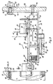
- a first roller or cylinder 01 of a color or printing unit of a printing press is swiveling or fixed in side frames.
- a second roller 02 with a sheath 13 made of elastic (rubber-elastic or elastomeric) plastic, e.g. As rubber or other rubbery material over a movable, z. B. cup-shaped pin receptacle 03 or axis recording (im also called “recording" for short).
- elastic rubber-elastic or elastomeric
- the roller 02 is at both ends on a respective bearing axis 06 by means of sliding or Rolling bearings rotatably mounted.
- Each bearing axis 06 is on a pin receiving 03, z. B. secured by a screw 04 against rotation. This happens z. B. by Screw the screw 04 through a hole in the pin receptacle 03 therethrough And in a threaded hole in the pin 06.
- a storage on cohesively attached to the roller 02 Pin 06 may be provided. But then it would have to camp on the recording 03 to be ordered.
- the bearing pin 06 of the roller 02 are in their respective associated cup-shaped Peg receptacle 03 attached.
- the pin receptacle 03 is fastened to a positioning plate 09 (eg welded on). These has a plurality of guide holes 11.
- a drive 24 actuator
- the pin receptacle 03 is fastened to a positioning plate 09 (eg welded on). These has a plurality of guide holes 11.
- a drive 24 actuator
- the drive 24 (actuator 24) can be used as a motor for linear movements, ie as a working cylinder with piston, be executed.
- the actuator 24 can be adjusted for power or output is.
- the drive 24 is designed as a motor for rectilinear movement.
- a double-acting cylinder 27 can be acted upon with gaseous or liquid medium (eg air or oil).
- gaseous or liquid medium eg air or oil.
- a vertical leg 16, i. a base plate 25, the bracket 14 is in each case an inner side of a machine frame 08 of a printing unit or inking unit adjustable in and against the vertical direction and attached fixed.
- adjusting device 26 may be located within an opening (hole) in the side frame 08 and at support him.
- the eccentric bush 23 has an external hexagonal adjustment head 22 via a rotational movement is introduced to the eccentric bush 23 by means of a key.
- a means for fixing 17 of the eccentric bushing 23 is provided.
- the locking screw 18 can be tightened secured so that the set position of the leg 16 and thus the position of the device 26 is not can change more.
- the (fastening) leg 16 is on his on the Diameter of the shaft 30 matched hole threaded onto the shaft 30. to additional assurance may be provided a ratchet screw 76 through a slot in the machine frame 08 through into a threaded hole in the Side frame 08 adjacent (mounting) leg 16 is screwed. hereby the leg 16 can be secured against the inner surface of the machine frame 08 be pressed.
- the Guide rods 12 have the task, in cooperation with on their cross section closely matched guide holes 11 of the actuator plate 09 along the guide rods 12 to permit and so a change in the distance 35 between the base plate 25 and Stellplatte 09 to reach.
- a stop 32 On the free end 45 of the rod 33 is a stop 32, z. B. in the form of a disc threaded.
- This stop 32 is with respect to the bottom 31 of the base plate 25th along the rod 33, z. B. threaded rod, adjustable in length.
- the stop 32 z. B. even with a first sprocket 36 or Gear 36 provided.
- the teeth of the ring gear or gear 36 is available a toothing of a drive gear 37 in engagement, as well as the stop 32nd also, is arranged below the base plate 25.
- the tooth width of the drive gear 37 is a multiple of the tooth width of the teeth of the ring gear 36th
- the drive gear 37 is connected to a direction reversible drive 39 (actuator), z. B. Motor for rotary motion (electric, stepper, hydraulic, pneumatic motor) via whose drive shaft 38 is rotationally connected.
- the drive 39 is depending on the version z. B. on the top 42 of the base plate 25 - so in the space between the adjusting plate 09 and the base plate 25 - the base plate 25 or attached to the underside 31.
- the drive shaft 38 with drive gear 39 protrudes a bore in the base plate 25 down out of it.
- the stop 32 - in this case as a hub of the Gear 36 are rotated by the drive gear 37.
- the adjusting nut 32 moves along the thread 44 of the Rod 32 on the bottom 31 of the base plate 25 toward or away from her. He can in any distance from the bottom 31 on the rod 33 and be held, but also the bottom 31 are stopped touching.
- the stop 32 can not only on the base plate 25, but also supported on the adjusting plate 09.
- a practically continuous contact pressure-dependent pressing of two directly adjacent rollers 01 and 02 is possible, depending on the contact pressure F A applied to the receptacle 09.
- the roller to be set 02 - and thus the recording 06 - sets at least one Anstellweg back to a final Anstell ein 96 of the roller 02.
- a measure of the contact pressure-dependent contact pressure is z. B. the indentation 07, z. B. highly elastic or rubber-elastic or elastomeric jacket 13 of the two rollers 01; 02 or the width of the so-called.
- At least one of the two rollers 01; 02 must have a rubber-elastic or highly elastic or elastomeric cover (jacket 13).
- roller 02 via its two bearing shafts 06 (only one ) Shown. But it would also be a flying storage possible, so you per roll 02 only one bearing axis or journal 06 would have.
- per bearing axis 06 is a device for adjusting 26 of a inking or dampening roller 01; 02 with a pin receptacle 03 with an available stroke 95 and a presettable setting force F A and holding force F F advantage.
- the limitation of the stroke 95 of the roller 02 to be adjusted is infinitely adjustable. This is done by the change in position of the stop 32 in the longitudinal axis direction on the rod 33. Or in other words, the position of the stop 32 of the actuator plate 09 in relation to the frame base plate 25 is fixed and lockable.
- the stop 32 (adjusting nut) must be at a sufficiently large distance 43 to a stop surface 31 fixed to the side frame - in this case the underside 31 of the base plate 25. be brought (see dashed line shown gear 36 and stop 32 in Fig. 1).
- the actuating plate 09 with pin receptacle 03 is moved away from the machine frame-fixed, directly or indirectly supporting the machine frame 08 base plate 25 of the drive 24 with preset contact force F A.
- this movement also follows the roller 02 with its z. B. elastomeric shell 13 in the direction of roller 01.
- the gear 36 is driven and thus the stopper 32 is moved in the opposite direction of rotation until it finally abuts against the stop surface 31 with torque and force that can be preselected via the drive 39 and is easily tightened.
- the drive 39 is stopped and the setting pressure P A or the setting force F A is increased by a multiple of the F A (eg quadruple) by means of the drive 24, thus achieving a preset holding force F F or holding pressure P F.
- the stopper 32 is pressed or pulled even more against the stop surface 31, because the drive 24 acts in the manner to move the actuator plate 09 and base plate 25 to each other. In this operating state, a change in the axial distance on the rollers 01 and 02 in the direction of roller 01 is practically no longer possible.
- the recording 06 is thus blocked in their ability to move.
- This holding pressure / force P F / F F is applied during the entire operating time. If the roller 02 is turned off, the direction of the holding pressure or the holding force is reversed and the adjusting plate 09 is pulled in the direction of the base plate 25.
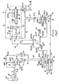
- the drive 24 is according to the invention as a double-acting pneumatic or hydraulic cylinder 24th (Actuator 24) with the piston chamber port 24 (4) and the piston rod space connection 24 (2) executed.
- Port 24 (2) is by means of a pneumatic or hydraulic line 47 with a first branch connection 51 (FIG. 2) of a first pneumatic or hydraulic Distributor 51 connected.
- a second branch port 51 (3) is either one Piston rod space connection of another actuator cylinder connected or locked.
- a supply port 51 (FIG. 1) of the first distributor 51 is provided by means of a pneumatic or hydraulic line 34 with a connection 48 (4) of a first, the 5/2-way valve 48 which serves as the "apply” or “apply” valve.
- a connection 48 (5) of the directional control valve 48 is by means of a pneumatic or hydraulic Intermediate line 60 via a port 57 with a first vent line 65th connected.
- Piston space connection 24 (4) of the adjusting cylinder 24 is by means of a pneumatic or hydraulic line 62 with a first branch connection 49 (2) of a second pneumatic or hydraulic distributor 49 connected.
- a second A foundede Trentsan gleich 49 (3) is either with a piston chamber port a connected or closed additional actuating cylinder.
- a feed connection 49 (FIG. 1) of the second distributor 49 is connected to a connection 48 (2). of the 5/2-way valve 48 by means of a pneumatic or hydraulic line 46th connected.
- a port 48 (1) of the 5/2-way valve 48 is by means of a pneumatic or hydraulic line 70 via a connection 58 of a second pneumatic or hydraulic pressure feed line 64 (pipe or hose line) connected.
- a first (access) port 48 (3) is by means of a pneumatic or hydraulic Line 75 (pipe or hose) via a port 59 with a second Vent line 66 (pipe or hose) connected.
- an electropneumatic or electro-hydraulic pressure control valve 78 is provided, hereinafter referred to as "E / P pressure control valve". This E / P pressure control valve 78 controls according to an analog remote adjustable electrical setpoint z. B. him proportional pressure P A from.
- the integrated electronics of the E / P pressure control valve 78 performs a comparison between the set contact pressure setpoint and the actual contact pressure P A of the working line 73 (actual pressure value), which is detected by means of a piezoresistive pressure sensor 86.
- a controller 87 generates a manipulated variable, which activates a 3/3-way valve 90 via a clocked U / I converter 88 and a proportional magnet 89, so that the preset "setting pressure" P A at the connection 90 (A) of the 3/3 Directional valve 90 is available.
- the working line 73 (pipe or hose) is connected at its first end.
- a second end of the working conduit 73 (tube or hose) is connected to a port 55 (4).
- a second 5/2-way valve 55 connected.
- a fluid pressure source 79 enters via an access 92 (1) of a manifold 92 with an operating pressure P B , which can be the holding pressure P F (eg 6 ⁇ 10 5 Pa to 12 ⁇ 10 5 Pa (6 -12 bar), charged, gaseous or liquid fluid (air or hydraulic oil) via first outlet 92 (3) of the manifold 92 to a port 90 (P1) of the 3/3-way valve 90 of the electropneumatic (or hydraulic) pressure control valve 78th
- a second outlet 92 (Fig. 2) of the manifold 92 is connected via a working line 72 (pipe or hose) to a port 55 (Fig. 2) of the second 5/2-way valve 55 (with two flow ports, two switch positions, proportional solenoid and return spring actuation) and detent position) connected.
- a connection 55 (FIG. 1) of the second 5/2-way valve 55 is connected via an intermediate line 84 the pressure feed line 64 connected.
- the terminals 55 (5) and 55 (1) of the Directional valve 55 are closed by means of closures 69 and 71.
- the "holding position” (shown in Figure 2) of the second directional control valve 55 is a higher pressure, the "holding pressure” P F , z. B. the plant operating pressure of 10 6 Pa (10 bar).
- the second directional valve 55 communicates to the terminal 48 (1) the "positioning pressure P A. In. This is generally smaller than the" fixing pressure P F ".”
- the positioning pressure P A is by means of the pressure control valve 78 on, for example, 10 4 Pa to 8 ⁇ 10 5 Pa (0.1 to 8.0 bar) einregelbar and consistently maintained.
- the "holding position" of the 5/2-way valve 55 is a flow made between terminals 55 (2) and 55 (1).
- the directional control valve 48 also has two positions. A second position, the so-called “Adjustment” and the first position, the so-called. "Abstellwolf” (shown in Figure 2).
- the piston space of the actuating cylinder 24 is here via 24 (4), 46, 49 (2), 49 (1), 62, 48 (2), 48 (3) and vent line 66 vented.
- the roller 02 In the "off position", the roller 02 is turned off by the roller 01.
- the second directional control valve 55 is connected - flow between ports 55 (2) and 55 (1) - that on the feed line 64, the high operating pressure P B , which may be equal to the set pressure P F , is.
- the directional control valve 48 is in "storage position" (shown in Figure 2). Ports 48 (2) and 48 (1), on the one hand, and ports 48 (4) and 48 (5), on the other hand, are flow switched. It follows that in the piston chamber of the cylinder 24, the full pressure P F and P B prevails and the adjusting plate 09 is moved away with the attached thereto cylinder 02 from the cylinder 01 up to a predetermined distance. Via the connections 48 (4) and 48 (5) is exhausted via line 60 and first vent line 65.
- the cylinder 01 is in "roll off position" after completion of this process.
- Actual value output 81 is connected via an electrical connection line 81 and connection 52 (81) and setpoint input 82 is connected to the control device 52 via an electrical connection line 54 and connection 52 (82).
- the power supply 56 of the control unit 52 via its terminal 52 (56). There are provided a sufficient number of displays of the set target pressure and the actual pressure at the central machine control station.
- the drive 39 is acted upon in such a way that the stop 32 bears against the stop surface 31, 42, 20 associated with it and shuts off when it reaches, for example, a preselected torque or motor current.
- the drive 39 can be controlled by the control device 52 via the electrical supply line 41 in clockwise and anti-clockwise rotation.
- a device 26 for adjusting the contact pressure F A or locking force F F per bearing journal or bearing axis 06 is provided.
- two devices 26 are provided, which are either individually or jointly presettable and / or engageable, so that it acts on one or both axis shots 06 per roller 02.
Landscapes
- Engineering & Computer Science (AREA)
- Mechanical Engineering (AREA)
- Inking, Control Or Cleaning Of Printing Machines (AREA)
- Rotary Presses (AREA)
- Rolls And Other Rotary Bodies (AREA)
Claims (3)
- Procédé pour régler un rouleau (02) d'une machine à imprimer, au moyen d'un vérin de déplacement (24), le rouleau (02), pendant la production, étant pressé contre une butée, en étant sollicité par une première force, caractérisé en ce que, pendant le réglage au moyen du vérin de déplacement (24), le rouleau (02)est sollicité par une deuxième force, en ce que le vérin de déplacement (24) est commandé en alimentation par une soupape de régulation de pression (78), électro-pneumatique ou électro-hydraulique.
- Procédé selon la revendication 1, caractérisé en ce que, pendant la production, la force est de valeur supérieure à celle que l'on a pendant le réglage.
- Procédé selon la revendication 1, caractérisé en ce qu'une pression de plaquage (PA) du rouleau (02) est commandée par la soupape de régulation de pression (78), de manière correspondant à une valeur de consigne électrique, pouvant faire l'objet d'un réglage à distance.
Applications Claiming Priority (3)
| Application Number | Priority Date | Filing Date | Title |
|---|---|---|---|
| DE19963944 | 1999-12-31 | ||
| DE19963944A DE19963944C1 (de) | 1999-12-31 | 1999-12-31 | Verfahren zum Einstellen einer Walze einer Druckmaschine |
| EP00991086A EP1246727B1 (fr) | 1999-12-31 | 2000-12-16 | Procédé pour régler un rouleau d'une machine à imprimer |
Related Parent Applications (1)
| Application Number | Title | Priority Date | Filing Date |
|---|---|---|---|
| EP00991086A Division EP1246727B1 (fr) | 1999-12-31 | 2000-12-16 | Procédé pour régler un rouleau d'une machine à imprimer |
Publications (3)
| Publication Number | Publication Date |
|---|---|
| EP1407882A2 EP1407882A2 (fr) | 2004-04-14 |
| EP1407882A3 EP1407882A3 (fr) | 2004-04-21 |
| EP1407882B1 true EP1407882B1 (fr) | 2005-04-13 |
Family
ID=7935106
Family Applications (2)
| Application Number | Title | Priority Date | Filing Date |
|---|---|---|---|
| EP00991086A Expired - Lifetime EP1246727B1 (fr) | 1999-12-31 | 2000-12-16 | Procédé pour régler un rouleau d'une machine à imprimer |
| EP03104185A Expired - Lifetime EP1407882B1 (fr) | 1999-12-31 | 2000-12-16 | Procédé pour régler un rouleau d'une machine à imprimer |
Family Applications Before (1)
| Application Number | Title | Priority Date | Filing Date |
|---|---|---|---|
| EP00991086A Expired - Lifetime EP1246727B1 (fr) | 1999-12-31 | 2000-12-16 | Procédé pour régler un rouleau d'une machine à imprimer |
Country Status (5)
| Country | Link |
|---|---|
| US (1) | US6668719B2 (fr) |
| EP (2) | EP1246727B1 (fr) |
| AT (2) | ATE293043T1 (fr) |
| DE (3) | DE19963944C1 (fr) |
| WO (1) | WO2001049491A2 (fr) |
Families Citing this family (13)
| Publication number | Priority date | Publication date | Assignee | Title |
|---|---|---|---|---|
| EP1066963B1 (fr) * | 1999-07-09 | 2003-02-19 | Gallus Ferd. Rüesch Ag | Mécanisme pour régler un espacement pour les outils dans des groupes imprimants |
| US7521481B2 (en) * | 2003-02-27 | 2009-04-21 | Mclaurin Joanne | Methods of preventing, treating and diagnosing disorders of protein aggregation |
| DE102004004665B4 (de) * | 2004-01-30 | 2005-12-29 | Koenig & Bauer Ag | Vorrichtung zum Einstellen einer von einer Walze in einem Walzenstreifen auf einen benachbarten Rotationskörper ausgeübten Anpresskraft und zum Anstellen der Walze an den Rotationskörper oder zum Abstellen der Walze von dem Rotationskörper |
| DE102004008090A1 (de) * | 2004-02-19 | 2005-09-08 | Man Roland Druckmaschinen Ag | Vorrichtung zum Positionieren einer Walze in einem Farb- oder Feuchtwerk einer Rotationsdruckmaschine |
| DE102004037889B4 (de) | 2004-04-05 | 2006-05-11 | Koenig & Bauer Ag | Vorrichtung zur Lagerung eines Zylinders und Druckeinheit mit wenigstens drei als Druckwerk zusammen wirkenden Zylindern |
| BRPI0509605A (pt) * | 2004-04-05 | 2007-09-18 | Koenig & Bauer Ag | unidade impressora de uma impressora rotativa de rolo |
| DE102004037888B4 (de) | 2004-04-05 | 2008-09-04 | Koenig & Bauer Aktiengesellschaft | Druckeinheiten einer Rollenrotationsdruckmaschine |
| DE102004038206A1 (de) * | 2004-08-05 | 2005-10-27 | Koenig & Bauer Ag | Lagereinheit eines Druckwerkzylinders sowie Druckeinheit |
| ATE510692T1 (de) * | 2004-12-10 | 2011-06-15 | Koenig & Bauer Ag | Anordnung eines zylinders einer bahnverarbeitenden maschine zur schwingungsreduktion des zylinders |
| DE102005045985B4 (de) | 2005-04-21 | 2012-11-29 | Koenig & Bauer Aktiengesellschaft | Druckeinheit und ein Verfahren zur Einstellung einer Druck-An-Stellung |
| DE102006003013B4 (de) * | 2005-06-17 | 2011-03-03 | Koenig & Bauer Aktiengesellschaft | Flexodruckmaschine |
| DE102006003006B4 (de) * | 2005-06-17 | 2014-01-23 | Koenig & Bauer Aktiengesellschaft | Verfahren zum Einstellen einer Druck-An-Stellung |
| DE102010043971B4 (de) * | 2010-11-16 | 2014-07-10 | Koenig & Bauer Aktiengesellschaft | Verfahren zum Einstellen eines sich längs zwischen einer Walze und einem in seiner Axialrichtung nebeneinander mit mehreren Druckformen belegbaren Formzylinder erstreckenden Abstandes |
Citations (2)
| Publication number | Priority date | Publication date | Assignee | Title |
|---|---|---|---|---|
| GB1213935A (en) * | 1968-02-07 | 1970-11-25 | Albert Schnellpressen | Improvements in or relating to inking apparatus for rotary printing presses |
| EP1029672A1 (fr) * | 1999-02-17 | 2000-08-23 | Heidelberger Druckmaschinen Aktiengesellschaft | Procédé et dispositif pour ajuster la force de pressage entre des rouleaux d'une machine à imprimer |
Family Cites Families (21)
| Publication number | Priority date | Publication date | Assignee | Title |
|---|---|---|---|---|
| DE708553C (de) * | 1934-06-17 | 1941-07-24 | Albert Schnellpressen | Farbwerk fuer Rotationsdruckmaschinen zum gleichzeitigen An- und Abstellen aller Farbwalzen |
| US3570399A (en) * | 1968-08-27 | 1971-03-16 | Winkler Fallert & Co Ltd | Adjustable support for rollers and printing presses |
| US3731620A (en) * | 1971-02-08 | 1973-05-08 | Appleton Mach | Hydraulic means for adjusting embossing cylinders in a rotary embosser |
| US4214528A (en) * | 1978-08-25 | 1980-07-29 | White Consolidated Industries, Inc. | Plate cylinder side register adjustment |
| US4290361A (en) * | 1980-01-11 | 1981-09-22 | American Newspaper Publishers Association | On the fly adjusting mechanism for rotary printing presses |
| DD210535A3 (de) | 1982-06-02 | 1984-06-13 | Polygraph Leipzig | Vorrichtung zum verstellen von farb- oder feuchtmittelauftragwalzen |
| DE3640161A1 (de) * | 1985-12-23 | 1987-07-02 | Escher Wyss Gmbh | Vorrichtung zum zueinander positionieren von walzenflaechen |
| DE3801429C2 (de) * | 1988-01-20 | 1998-05-20 | Siemens Ag | Druckvorrichtung mit verstellbarer Gegendruckrolle |
| DE3915481A1 (de) * | 1989-05-11 | 1990-12-13 | Windmoeller & Hoelscher | Vorrichtung zum anstellen und abheben eines auf einen formzylinder wirkenden gegendruckzylinders |
| DE3926087C1 (fr) * | 1989-08-07 | 1990-10-04 | Heidelberger Druckmaschinen Ag, 6900 Heidelberg, De | |
| CH683606A5 (fr) * | 1990-04-26 | 1994-04-15 | Bobst Sa | Dispositif avec vérin à précontrainte de contrôle de la pression de travail entre deux cylindres rotatifs coatifs dans une machine de traitement de matière en bande. |
| US5094162A (en) | 1990-08-30 | 1992-03-10 | A. B. Dick Company | Offset printing machine |
| DE4211379C2 (de) * | 1992-04-04 | 1999-01-07 | Roland Man Druckmasch | Anilox-Offset-Druckeinheit mit einem Kurzfarbwerk |
| DE4232163C3 (de) * | 1992-09-25 | 2001-09-06 | Koenig & Bauer Ag | Vorrichtung zum Aufrechterhalten einer eingestellten Anpressung einer Farbauftragswalze an einem Formzylinder einer Rotationsdruckmaschine |
| DE4335282C2 (de) | 1993-10-15 | 1998-01-29 | Wifag Maschf | Verfahren zur Steuerung des Ablaufs einer angetriebenen Farbauftragwalze in Bezug auf einen angetriebenen Formzylinder im Druckwerk einer Offsetrotationsdruckmaschine sowie ein entsprechend gesteuertes Druckwerk |
| DE29608887U1 (de) | 1996-05-17 | 1996-08-22 | MAN Roland Druckmaschinen AG, 63075 Offenbach | Druckschaltvorrichtung |
| EP0826501B2 (fr) * | 1996-09-03 | 2004-01-02 | Gimaco Ingenieur Ag Für Maschinenbau | Dispositif utilisé pour ajuster un rouleau d'encrage ou de mouillage dans une machine à imprimer |
| DE19719305A1 (de) * | 1997-05-07 | 1998-11-12 | Roland Man Druckmasch | Lageranordnung für eine Walze eines Farb- oder Feuchtwerkes |
| DE19740480B4 (de) | 1997-09-15 | 2005-07-21 | Man Roland Druckmaschinen Ag | Verfahren und Vorrichtung zum Anstellen einer Farbwalze einer Rotationsdruckmaschine |
| FR2778599B1 (fr) * | 1998-05-13 | 2000-08-04 | Heidelberger Druckmasch Ag | Dispositif de deplacement des cylindres de groupes d'impression de machines rotatives a imprimer |
| DE19919733A1 (de) * | 1998-05-22 | 1999-11-25 | Heidelberger Druckmasch Ag | Vorrichtung und Verfahren zum halbautomatischen Einstellen von Walzen |
-
1999
- 1999-12-31 DE DE19963944A patent/DE19963944C1/de not_active Expired - Fee Related
-
2000
- 2000-12-16 AT AT03104185T patent/ATE293043T1/de not_active IP Right Cessation
- 2000-12-16 WO PCT/DE2000/004503 patent/WO2001049491A2/fr not_active Ceased
- 2000-12-16 EP EP00991086A patent/EP1246727B1/fr not_active Expired - Lifetime
- 2000-12-16 DE DE50010361T patent/DE50010361D1/de not_active Expired - Lifetime
- 2000-12-16 US US10/168,531 patent/US6668719B2/en not_active Expired - Fee Related
- 2000-12-16 DE DE50010065T patent/DE50010065D1/de not_active Expired - Lifetime
- 2000-12-16 EP EP03104185A patent/EP1407882B1/fr not_active Expired - Lifetime
- 2000-12-16 AT AT00991086T patent/ATE295782T1/de not_active IP Right Cessation
Patent Citations (3)
| Publication number | Priority date | Publication date | Assignee | Title |
|---|---|---|---|---|
| GB1213935A (en) * | 1968-02-07 | 1970-11-25 | Albert Schnellpressen | Improvements in or relating to inking apparatus for rotary printing presses |
| EP1029672A1 (fr) * | 1999-02-17 | 2000-08-23 | Heidelberger Druckmaschinen Aktiengesellschaft | Procédé et dispositif pour ajuster la force de pressage entre des rouleaux d'une machine à imprimer |
| DE10001582A1 (de) * | 1999-02-17 | 2000-08-24 | Heidelberger Druckmasch Ag | Verfahren und Vorrichtung zum Einstellen des Anpressdrucks zwischen Walzen in einer Druckmaschine |
Also Published As
| Publication number | Publication date |
|---|---|
| WO2001049491A2 (fr) | 2001-07-12 |
| DE50010361D1 (de) | 2005-06-23 |
| WO2001049491A3 (fr) | 2001-11-15 |
| DE50010065D1 (de) | 2005-05-19 |
| US20030089254A1 (en) | 2003-05-15 |
| EP1246727B1 (fr) | 2005-05-18 |
| DE19963944C1 (de) | 2001-06-13 |
| EP1246727A2 (fr) | 2002-10-09 |
| ATE293043T1 (de) | 2005-04-15 |
| WO2001049491B1 (fr) | 2001-12-27 |
| US6668719B2 (en) | 2003-12-30 |
| ATE295782T1 (de) | 2005-06-15 |
| EP1407882A2 (fr) | 2004-04-14 |
| EP1407882A3 (fr) | 2004-04-21 |
Similar Documents
| Publication | Publication Date | Title |
|---|---|---|
| EP1437221B1 (fr) | Dispositif de réglage d'une pression d'impression d'un rouleau monté de facon réglable | |
| EP1246727B1 (fr) | Procédé pour régler un rouleau d'une machine à imprimer | |
| EP1461207A2 (fr) | Procede pour faire fonctionner un dispositif d'encrage ou un dispositif de mouillage dans une machine a imprimer | |
| DE10001582A1 (de) | Verfahren und Vorrichtung zum Einstellen des Anpressdrucks zwischen Walzen in einer Druckmaschine | |
| EP1570985A2 (fr) | Dispositif pour régler la force de pression d'un rouleau réglable | |
| EP0396904A2 (fr) | Dispositif de soulèvement et d'abaissement d'un cylindre d'impression agissant sur un cylindre de cliché | |
| EP0826501A1 (fr) | Dispositif utilisé pour ajuster un rouleau d'encrage ou de mouillage dans une machine à imprimer | |
| DE10113314C2 (de) | Fixiereinrichtung | |
| EP0125670B1 (fr) | Dispositif pour imprimer | |
| EP0813960A1 (fr) | Cylindres d'imprimerie supportés en porte-à-faux | |
| DE4112666C2 (de) | Vorrichtung zur Fernbedienung von Klemmeinrichtungen an Zylindern in Rotationsdruckmaschinen | |
| EP1757447A2 (fr) | Unité d'impression d'une machine à imprimer | |
| EP1871600A2 (fr) | Unite d'impression et procede de reglage d'une position d'impression | |
| DE10244046B4 (de) | Vorrichtung zum Einstellen des Anpressdrucks einer verstellbar gelagerten Walze | |
| DE2129017C3 (de) | Steuereinrichtung an einer Honmaschine zum gleichzeitigen Bearbeiten von mindestens zwei koaxial hintereinanderliegenden Bohrungen | |
| DE3337309C2 (de) | Vorrichtung zum Druckan- und abstellen eines auf einen Formzylinder wirkenden Gegendruckzylinders einer Rollen-Rotationsdruckmaschine | |
| DE2129750A1 (de) | Vorrichtung zum Aneinanderbewegen zweier Koerper | |
| DE3543655C2 (fr) | ||
| DE9108408U1 (de) | Vorrichtung zur Beseitigung von Schrägverzügen in einer laufenden Warenbahn | |
| EP1497128B1 (fr) | Procede et dispositifs de reglage de cylindres montes de maniere reglable | |
| EP0686502A2 (fr) | Installation pour réduire la flexion d'un cylindre dans des machines d'impression rotatives | |
| DE2336195A1 (de) | Hydraulische servolenkeinrichtung fuer kraftfahrzeuge | |
| DE102010043971B4 (de) | Verfahren zum Einstellen eines sich längs zwischen einer Walze und einem in seiner Axialrichtung nebeneinander mit mehreren Druckformen belegbaren Formzylinder erstreckenden Abstandes | |
| DE1475927C (de) | Steuerventil fur die Steuerung eines hydraulischen Kolben-Stellmotors | |
| DE2059752C (de) | Einrichtung an einem Farbwerk von Ro tationsdruckmaschinen, insbesondere Off setdruckmaschinen, zum An und Abstellen einer Farbauftragwalze |
Legal Events
| Date | Code | Title | Description |
|---|---|---|---|
| PUAI | Public reference made under article 153(3) epc to a published international application that has entered the european phase |
Free format text: ORIGINAL CODE: 0009012 |
|
| PUAL | Search report despatched |
Free format text: ORIGINAL CODE: 0009013 |
|
| AC | Divisional application: reference to earlier application |
Ref document number: 1246727 Country of ref document: EP Kind code of ref document: P |
|
| AK | Designated contracting states |
Kind code of ref document: A2 Designated state(s): AT BE CH CY DE DK ES FI FR GB GR IE IT LI LU MC NL PT SE TR |
|
| AK | Designated contracting states |
Kind code of ref document: A3 Designated state(s): AT BE CH CY DE DK ES FI FR GB GR IE IT LI LU MC NL PT SE TR |
|
| 17P | Request for examination filed |
Effective date: 20040326 |
|
| GRAP | Despatch of communication of intention to grant a patent |
Free format text: ORIGINAL CODE: EPIDOSNIGR1 |
|
| GRAS | Grant fee paid |
Free format text: ORIGINAL CODE: EPIDOSNIGR3 |
|
| AKX | Designation fees paid |
Designated state(s): AT BE CH CY DE DK ES FI FR GB GR IE IT LI LU MC NL PT SE TR |
|
| GRAA | (expected) grant |
Free format text: ORIGINAL CODE: 0009210 |
|
| AC | Divisional application: reference to earlier application |
Ref document number: 1246727 Country of ref document: EP Kind code of ref document: P |
|
| AK | Designated contracting states |
Kind code of ref document: B1 Designated state(s): AT BE CH CY DE DK ES FI FR GB GR IE IT LI LU MC NL PT SE TR |
|
| PG25 | Lapsed in a contracting state [announced via postgrant information from national office to epo] |
Ref country code: IT Free format text: LAPSE BECAUSE OF FAILURE TO SUBMIT A TRANSLATION OF THE DESCRIPTION OR TO PAY THE FEE WITHIN THE PRESCRIBED TIME-LIMIT;WARNING: LAPSES OF ITALIAN PATENTS WITH EFFECTIVE DATE BEFORE 2007 MAY HAVE OCCURRED AT ANY TIME BEFORE 2007. THE CORRECT EFFECTIVE DATE MAY BE DIFFERENT FROM THE ONE RECORDED. Effective date: 20050413 Ref country code: TR Free format text: LAPSE BECAUSE OF FAILURE TO SUBMIT A TRANSLATION OF THE DESCRIPTION OR TO PAY THE FEE WITHIN THE PRESCRIBED TIME-LIMIT Effective date: 20050413 Ref country code: NL Free format text: LAPSE BECAUSE OF FAILURE TO SUBMIT A TRANSLATION OF THE DESCRIPTION OR TO PAY THE FEE WITHIN THE PRESCRIBED TIME-LIMIT Effective date: 20050413 Ref country code: IE Free format text: LAPSE BECAUSE OF FAILURE TO SUBMIT A TRANSLATION OF THE DESCRIPTION OR TO PAY THE FEE WITHIN THE PRESCRIBED TIME-LIMIT Effective date: 20050413 Ref country code: FI Free format text: LAPSE BECAUSE OF FAILURE TO SUBMIT A TRANSLATION OF THE DESCRIPTION OR TO PAY THE FEE WITHIN THE PRESCRIBED TIME-LIMIT Effective date: 20050413 |
|
| REG | Reference to a national code |
Ref country code: GB Ref legal event code: FG4D Free format text: NOT ENGLISH |
|
| REG | Reference to a national code |
Ref country code: CH Ref legal event code: EP |
|
| REG | Reference to a national code |
Ref country code: IE Ref legal event code: FG4D Free format text: LANGUAGE OF EP DOCUMENT: GERMAN |
|
| REF | Corresponds to: |
Ref document number: 50010065 Country of ref document: DE Date of ref document: 20050519 Kind code of ref document: P |
|
| PG25 | Lapsed in a contracting state [announced via postgrant information from national office to epo] |
Ref country code: SE Free format text: LAPSE BECAUSE OF FAILURE TO SUBMIT A TRANSLATION OF THE DESCRIPTION OR TO PAY THE FEE WITHIN THE PRESCRIBED TIME-LIMIT Effective date: 20050713 Ref country code: GR Free format text: LAPSE BECAUSE OF FAILURE TO SUBMIT A TRANSLATION OF THE DESCRIPTION OR TO PAY THE FEE WITHIN THE PRESCRIBED TIME-LIMIT Effective date: 20050713 Ref country code: DK Free format text: LAPSE BECAUSE OF FAILURE TO SUBMIT A TRANSLATION OF THE DESCRIPTION OR TO PAY THE FEE WITHIN THE PRESCRIBED TIME-LIMIT Effective date: 20050713 |
|
| PG25 | Lapsed in a contracting state [announced via postgrant information from national office to epo] |
Ref country code: ES Free format text: LAPSE BECAUSE OF FAILURE TO SUBMIT A TRANSLATION OF THE DESCRIPTION OR TO PAY THE FEE WITHIN THE PRESCRIBED TIME-LIMIT Effective date: 20050724 |
|
| GBT | Gb: translation of ep patent filed (gb section 77(6)(a)/1977) |
Effective date: 20050802 |
|
| PG25 | Lapsed in a contracting state [announced via postgrant information from national office to epo] |
Ref country code: PT Free format text: LAPSE BECAUSE OF FAILURE TO SUBMIT A TRANSLATION OF THE DESCRIPTION OR TO PAY THE FEE WITHIN THE PRESCRIBED TIME-LIMIT Effective date: 20050913 |
|
| NLV1 | Nl: lapsed or annulled due to failure to fulfill the requirements of art. 29p and 29m of the patents act | ||
| REG | Reference to a national code |
Ref country code: IE Ref legal event code: FD4D |
|
| PG25 | Lapsed in a contracting state [announced via postgrant information from national office to epo] |
Ref country code: CY Free format text: LAPSE BECAUSE OF FAILURE TO SUBMIT A TRANSLATION OF THE DESCRIPTION OR TO PAY THE FEE WITHIN THE PRESCRIBED TIME-LIMIT Effective date: 20051216 Ref country code: AT Free format text: LAPSE BECAUSE OF NON-PAYMENT OF DUE FEES Effective date: 20051216 |
|
| PG25 | Lapsed in a contracting state [announced via postgrant information from national office to epo] |
Ref country code: MC Free format text: LAPSE BECAUSE OF NON-PAYMENT OF DUE FEES Effective date: 20051231 Ref country code: BE Free format text: LAPSE BECAUSE OF NON-PAYMENT OF DUE FEES Effective date: 20051231 Ref country code: LU Free format text: LAPSE BECAUSE OF NON-PAYMENT OF DUE FEES Effective date: 20051231 |
|
| ET | Fr: translation filed | ||
| PLBE | No opposition filed within time limit |
Free format text: ORIGINAL CODE: 0009261 |
|
| STAA | Information on the status of an ep patent application or granted ep patent |
Free format text: STATUS: NO OPPOSITION FILED WITHIN TIME LIMIT |
|
| 26N | No opposition filed |
Effective date: 20060116 |
|
| BERE | Be: lapsed |
Owner name: KOENIG & BAUER A.G. Effective date: 20051231 |
|
| PGFP | Annual fee paid to national office [announced via postgrant information from national office to epo] |
Ref country code: FR Payment date: 20110107 Year of fee payment: 11 |
|
| PGFP | Annual fee paid to national office [announced via postgrant information from national office to epo] |
Ref country code: CH Payment date: 20101229 Year of fee payment: 11 |
|
| PGFP | Annual fee paid to national office [announced via postgrant information from national office to epo] |
Ref country code: GB Payment date: 20101224 Year of fee payment: 11 |
|
| REG | Reference to a national code |
Ref country code: CH Ref legal event code: PL |
|
| GBPC | Gb: european patent ceased through non-payment of renewal fee |
Effective date: 20111216 |
|
| REG | Reference to a national code |
Ref country code: FR Ref legal event code: ST Effective date: 20120831 |
|
| PG25 | Lapsed in a contracting state [announced via postgrant information from national office to epo] |
Ref country code: GB Free format text: LAPSE BECAUSE OF NON-PAYMENT OF DUE FEES Effective date: 20111216 Ref country code: LI Free format text: LAPSE BECAUSE OF NON-PAYMENT OF DUE FEES Effective date: 20111231 Ref country code: CH Free format text: LAPSE BECAUSE OF NON-PAYMENT OF DUE FEES Effective date: 20111231 |
|
| PGFP | Annual fee paid to national office [announced via postgrant information from national office to epo] |
Ref country code: DE Payment date: 20121207 Year of fee payment: 13 |
|
| PG25 | Lapsed in a contracting state [announced via postgrant information from national office to epo] |
Ref country code: FR Free format text: LAPSE BECAUSE OF NON-PAYMENT OF DUE FEES Effective date: 20120102 |
|
| REG | Reference to a national code |
Ref country code: DE Ref legal event code: R119 Ref document number: 50010065 Country of ref document: DE |
|
| REG | Reference to a national code |
Ref country code: DE Ref legal event code: R119 Ref document number: 50010065 Country of ref document: DE Effective date: 20140701 |
|
| PG25 | Lapsed in a contracting state [announced via postgrant information from national office to epo] |
Ref country code: DE Free format text: LAPSE BECAUSE OF NON-PAYMENT OF DUE FEES Effective date: 20140701 |